Table of Contents
Advertisement
Quick Links
Advertisement
Table of Contents

Related Manuals for Asus AAEON SRG-ACAN


Summary of Contents for Asus AAEON SRG-ACAN
- Page 1 SRG-ACAN IoT Gateway System User’s Manual 1 Last Updated: August 13, 2021...
- Page 2 Copyright Notice This document is copyrighted, 2021. All rights are reserved. The original manufacturer reserves the right to make improvements to the products described in this manual at any time without notice. No part of this manual may be reproduced, copied, translated, or transmitted in any form or by any means without the prior written permission of the original manufacturer.
- Page 3 Acknowledgements All other products’ name or trademarks are properties of their respective owners. Microsoft Windows is a registered trademark of Microsoft Corp. ⚫ Intel® is a registered trademark of Intel Corporation ⚫ ARM, Cortex, and Cortex-A8 are registered trademarks of Arm Limited (or its ⚫...
- Page 4 Packing List Before setting up your product, please make sure the following items have been shipped: Item Quantity SRG-ACAN ⚫ If any of these items are missing or damaged, please contact your distributor or sales representative immediately. Preface...
- Page 5 About this Document This User’s Manual contains all the essential information, such as detailed descriptions and explanations on the product’s hardware and software features (if any), its specifications, dimensions, jumper/connector settings/definitions, and driver installation instructions (if any), to facilitate users in setting up their product. Users may refer to the product page at AAEON.com for the latest version of this document.
- Page 6 Safety Precautions Please read the following safety instructions carefully. It is advised that you keep this manual for future references All cautions and warnings on the device should be noted. All cables and adapters supplied by AAEON are certified and in accordance with the material safety laws and regulations of the country of sale.
- Page 7 As most electronic components are sensitive to static electrical charge, be sure to ground yourself to prevent static charge when installing the internal components. Use a grounding wrist strap and contain all electronic components in any static-shielded containers. If any of the following situations arises, please the contact our service personnel: Damaged power cord or plug Liquid intrusion to the device iii.
- Page 8 FCC Statement This device complies with Part 15 FCC Rules. Operation is subject to the following two conditions: (1) this device may not cause harmful interference, and (2) this device must accept any interference received including interference that may cause undesired operation.
- Page 9 China RoHS Requirements (CN) 产品中有毒有害物质或元素名称及含量 AAEON System QO4-381 Rev.A0 有毒有害物质或元素 部件名称 铅 汞 镉 六价铬 多溴联苯 多溴二苯 (Pb) (Hg) (Cd) 醚(PBDE) (Cr(VI)) (PBB) 印刷电路板 × ○ ○ ○ ○ ○ 及其电子组件 外部信号 × ○ ○ ○ ○ ○ 连接器及线材 外壳 ○...
- Page 10 China RoHS Requirement (EN) Hazardous and Toxic Materials List AAEON System QO4-381 Rev.A0 Hazardous or Toxic Materials or Elements Component Name PCB and Components Wires & Connectors for Ext.Connections Chassis CPU & RAM HDD Drive LCD Module Optical Drive Touch Control Module Battery This form is prepared in compliance with the provisions of SJ/T 11364.
-
Page 11: Table Of Contents
Table of Contents Chapter 1 - Product Specifications..................1 Specifications ......................2 Chapter 2 – Hardware Information ..................5 Dimensions ....................... 6 I/O Location ......................7 Wireless Hardware Setup ..................9 2.3.1 Mini Card Installation .................. 9 2.3.2 SIM Card Installation .................. 11 Chapter 3 –... - Page 12 3.5.8 Check Pared Bluetooth Devices .............. 25 System Management .................... 26 3.6.1 Check OS Version ..................26 3.6.2 Check Storage Status ................27 3.6.3 Shut Down the System ................27 3.6.4 Set Date and Time ..................28 I/O Management ....................29 3.7.1 Control GPIO (LEDs) ..................
-
Page 13: Chapter 1 - Product Specifications
Chapter 1 Chapter 1 - Product Specifications... -
Page 14: Specifications
Specifications General ARM Cortex-A8 800 MHz RISC Processor Memory DDR3L 1GB Storage eMMC 8GB OS Support Debian 10 (Buster) RTC Supported Security TPM 2.0 Interface Ethernet Ports 2 x Auto-sensing 10/100/1000 Mbps ports (RJ45 connector) USB Ports 2 x USB2.0 (Type A Connector) Serial Ports 1 x DB-9 RS232/422/485 (switchable) Expansion Ports... - Page 15 Radio Frequency Interface Wi-Fi IEEE Std 802.11b/g/n Bluetooth Bluetooth 4.2 and Bluetooth low energy Physical Characteristics Dimensions 4.3” x 4.33” x 1.54” (109mm x 110mm x 39mm) Weight 430 g Mounting DIN-rail mounting, Wall Mount Environmental Operating Temperature 32°F ~ 140°F (0°C ~ 60°C) Operating Humidity 10% ~ 95% relative humidity, non-condensing Storage Temperature...
- Page 16 Certification CE Red EMC: EN301489-1/-17 RF: EN300328 (Wi-Fi, Bluetooth, 2.4GHz) Safety: EN 62368-1 Green Product RoHS MTBF 855,890 Hours Chapter 1 – Product Specifications...
-
Page 17: Chapter 2 - Hardware Information
Chapter 2 Chapter 2 – Hardware Information... -
Page 18: Dimensions
Dimensions Chapter 2 – Hardware Information... -
Page 19: I/O Location
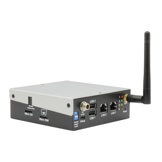
I/O Location Reference Function Antenna Connector Antenna connector for 2.4G or LTE Reset Button Reboots the system Debug Port User can log into the gateway’s operating system via SSH with debug port (Micro USB connector) RS-485 Terminal Resistor Used with long distance connection between gateway and RS-485 device Micro SIM Slot Insert a Micro SIM card here when using an LTE Mini Card Module... - Page 20 Reference Function Gigabit LAN Port Standard RJ-45 LAN jack to connect with Local Area Network Function Status Yellow Active status ON: LAN link is established. OFF: LAN link is not established. Blink: Data received and transmitted. Orange Link Speed Green on: 10/100Mbps. /Green status Orange on: 1000Mbps.
-
Page 21: Wireless Hardware Setup
Wireless Hardware Setup The SRG-ACAN features both a SIM Card and Mini Card slot for connecting to wireless networks such as 4G. This section details how to install a SIM Card and 4G/LTE module on the mini card slot. 2.3.1 Mini Card Installation Step 1: Remove the six screws securing the top cover. - Page 22 Step 4: Remove the bottom access panel. Install the 4G/LTE module by inserting at an angle into the Mini Card slot, pressing down gently and securing with a screw. Step 5: Connect the antenna cable to the module. Step 6: Replace the bottom panel, then the top cover. Chapter 2 –...
-
Page 23: Sim Card Installation
2.3.2 SIM Card Installation To install a SIM Card (Micro SIM) simply insert the SIM Card into the slot on the side of the system as shown. Take care to make sure the card is oriented correctly. Chapter 2 – Hardware Information... -
Page 24: Chapter 3 - Gateway Setup And Configuration
Chapter 3 Chapter 3 – Gateway Setup and Configuration... -
Page 25: Connecting To System
Connecting to System When connecting a PC or laptop to the SRG-ACAN system, it is recommended to use PuTTY with Windows 10. Users can download the software from the PuTTY website. https://www.putty.org/ For Windows 7 or older, users must first set up their PC to recognize the system. The following instructions detail how to set up your PC to connect to the SRG-ACAN system by installing the CDC Serial Driver. - Page 26 Step 4: Open PuTTY and use the following settings to connect to the system. Serial Port Settings Baud Rate 115200 bps Parity None Data bits Stop bits Flow Control None Click “Open” to connect with the gateway system. Chapter 3 – Gateway Setup and Configuration...
- Page 27 Step 5: You will see the login prompt once the host PC successfully connects to the gateway. Default login information is: Username: aaeon Password: aaeon Chapter 3 – Gateway Setup and Configuration...
-
Page 28: User Account Management
User Account Management This section details how to manage user accounts on the system. Add User Account Command Line: ✓ $ sudo useradd -m -G sudo -s /bin/bash USERACCOUNT USERACCOUNT -> Account name you want to add Return (test3 is the account name in this example): ✓... -
Page 29: Network Settings
Network Settings This section details how to check and setup the network settings. 3.3.1 Check IP Settings: Check the IP setting by entering the following command into Terminal/Command Line: $ nmcli con show NETWORKPROFILE NETWORKPROFILE refers to one of the system’s network connections as follows: NETWORKPROFILE Port/Hardware Ethernet0... -
Page 30: Set Static Ip
3.3.2 Set Static IP Step 1: Enter edit mode with the following command: $ nmcli con edit NETWORKPROFILE See table in 3.3.1 for NETWORKPROFILE values Command should return the following (Ethernet0 used in this example): Step 2: Edit the IP Address with the following commands: $ nmcli>... -
Page 31: Set Dynamic Ip
3.3.3 Set Dynamic IP Step 1: Enter edit mode with the following command: $ nmcli con edit NETWORKPROFILE See table in 3.3.1 for NETWORKPROFILE values Command should return the following (Ethernet0 used in this example): Step 2: Edit the IP address with the following commands: $ nmcli>... -
Page 32: Cellular Network Settings
Cellular Network Settings This section details how to check and manage the cellular network settings. 3.4.1 Check Cellular Module Status Step 1: To check the status of the cellular module, enter the following command: $ mmcli -m 0 The system should output the following: Chapter 3 –... -
Page 33: Dial Up Cellular Module
3.4.2 Dial Up Cellular Module Step 1: Follow the steps in the previous section to check the cellular module status. The system should return a state of “registered” under Status if the module is ready to use. If there is an issue, the state will show “failed” along with a failed reason such as “sim missing”. -
Page 34: Wi-Fi And Bluetooth Network Settings
Wi-Fi and Bluetooth Network Settings This section details how to check and setup Wi-Fi and Bluetooth wireless networks. 3.5.1 Scan for Wi-Fi Access Points To scan for Wi-Fi access points, enter the following command: $ nmcli dev wifi The system will return a list of Wi-Fi networks with their name, signal strength and security type. -
Page 35: Disconnect From Wi-Fi Access Point
3.5.3 Disconnect from Wi-Fi Access Point To disconnect from a Wi-Fi network, enter the following command: $ sudo nmcli con down id ‘SSID’ SSID is the name of the network you want to disconnect from The system will return the following if successful: 3.5.4 Check Wi-Fi Connection Status To check the status of a Wi-Fi connection, enter the following command:... -
Page 36: Enter Bluetooth Control Panel
3.5.5 Enter Bluetooth Control Panel Before managing Bluetooth settings, you must first enter the Bluetooth Control Panel with the following command: $ sudo bluetoothctl The system will return the following: 3.5.6 Scan for Bluetooth Device To scan for a Bluetooth Device, enter the following commands: $ power on This command turns on the Bluetooth module $ scan on... -
Page 37: Pair Bluetooth Device
3.5.7 Pair Bluetooth Device To pair a Bluetooth Device, enter the following command while in the control panel: $ pair MAC_ID MAC_ID is the MAC address of the device you wish to connect to. This example is connecting to device E8:6F:38:83:CF:10 3.5.8 Check Pared Bluetooth Devices To check which Bluetooth devices are paired with the system, use the command:... -
Page 38: System Management
System Management This section details how to check the OS version, storage device status, shutdown the system and set the date and time. 3.6.1 Check OS Version To check which OS version the system is running, enter the command: $ cat /etc/os-release The system will return the OS information: Chapter 3 –... -
Page 39: Check Storage Status
3.6.2 Check Storage Status To check the status of the system storage, enter the following command: $ df -h The system will return a list of storage devices, capacity and usage 3.6.3 Shut Down the System To force the system to shut down, use following command. Note, you may need to enter the user password. -
Page 40: Set Date And Time
3.6.4 Set Date and Time Step 1: Check current date and time by issuing the following command: $ timedatectl The system will return the current system clock settings Step 2: Change the date and time by issuing the following command: $ date MMDDhhmmYYYY Command uses the following formatting: MM –... -
Page 41: I/O Management
I/O Management This section details how to operate the programable I/O functions; GPIO and RS-485 2-wire connectors. 3.7.1 Control GPIO (LEDs) To control the GPIO manually, issue the following commands, this example uses led1: GPIO On: $ echo 1 > /sys/class/leds/srt3352:led1/brightness GPIO Off: $ echo 0 >... -
Page 42: Rs-485 2-Wire Pin Definition
3.7.2 RS-485 2-wire Pin Definition Label System Reference COM1 /dev/ttyS4 COM2 /dev/ttyS5 Signal DATA+ DATA- Chapter 3 – Gateway Setup and Configuration... -
Page 43: Rs-232/422/485, Can Bus Pin Definitions
3.7.3 RS-232/422/485, CAN Bus Pin Definitions Label System Reference COM1 /dev/ttyMU0 COM2 /dev/ttyMU1 COM1 Signal COM2 Signal CAN Signal AI_2 AI_4 CAN1_H CAN0_H AI_1 AI_3 CAN1_L CAN0_L Chapter 3 – Gateway Setup and Configuration... -
Page 44: Manage Rs-232/422/485 Mode
3.7.3.1 Manage RS-232/422/485 Mode Check Current Mode by entering the following command: $ sudo uartmode -p PORTNO PORTNO is the label of each port: PORTNO System Name Port Label /dev/ttyMU0 COM1 /dev/ttyMU1 COM2 Example: will return mode for COM1 $ sudo uartmode -p The command will output a single number. -
Page 45: Can Bus Read/Write
3.7.3.2 CAN Bus Read/Write To command the CAN Bus to Read or Write, use the following commands: Initialize CAN Bus: $ sudo srg52-initcan CANNO BAUDRATE CAN Bus Read: $ sudo can_read CANNO CAN Bus Write: $ sudo can_write CANNO CANNO variable is either can0 or can1 CANNO System Name... -
Page 46: Adc, Digital I/O Pin Definitions
3.7.4 ADC, Digital I/O Pin Definitions COM1 Signal COM2 Signal VCC+ DI_Common (VCC+) VCC- DI_1 DO_2 DI_2 DO_3 DI_3 DO_4 DI_4 DO_1 AI_1 AI_2 AI_3 AI_GND AI_4 Chapter 3 – Gateway Setup and Configuration... -
Page 47: Wiring Diagram
3.7.4.1 Wiring Diagram Analog Input: Digital Input: Chapter 3 – Gateway Setup and Configuration... - Page 48 Digital Output Chapter 3 – Gateway Setup and Configuration...
-
Page 49: Manage Digital I/O
3.7.4.2 Manage Digital I/O Set Digital Output State Use the following command to set digital output state to ON or OFF $ setdo CHANNEL STATE CHANNEL 0, 1, 2, or 3 STATE set to 1 for ON or 0 for OFF Example: Get Digital Input Status Use the following command to check the status of digital input:... -
Page 50: Manage Analog Input (4Ch Signal End)
3.7.4.3 Manage Analog Input (4CH Signal End) Enter the following command to view status for all channels: $ rd_exadc -a Config-CH0 Config-CH1 Config-CH2 Config-CH3 Config-CH# for each channel use the following numerical inputs: Voltage Current Disable (no value will be returned) For example: The following command will return voltage values for all four channels: $ rd_exadc -a... -
Page 51: Manage Analog Input (2Ch Differential)
3.7.4.4 Manage Analog Input (2CH Differential) To check Group status, use the following command: $ rd_exadc -g GROUP -m 0 GROUP enter 0 for group 0 (ch0 and ch1); enter 1 for group 1 (ch2 and ch3) The system will return the following: Chapter 3 –...