Table of Contents
Advertisement
COPYRIGHT
Fu j i t su
PC Corpora ti on has made every e ort to
™
en su re the acc u racy and com p l eteness of this doc u m en t .
However, as on going devel opm ent e orts are con ti n -
u a lly improving the capabi l i ties of our produ ct s , we
cannot guara n tee the acc u racy of the con tents of t h i s
doc u m en t . We disclaim liabi l i ty for errors , om i s s i on s ,
or futu re ch a n ge s .
LifeBook, Fujitsu,and the Fujitsu logo are trademarks
of Fujitsu Limited.
The fo ll owing are regi s tered tradem a rks of
IBM Corpora ti on :I B M , IBM PC AT, IBM PS/2.
The fo ll owing are regi s tered tradem a rks of
Mi c ro s oft Corpora ti on :M S ,M S - DO S , Wi n dows 95.
PCMCIA is a tradem a rk of the Pers onal Com p uter
Mem ory Ca rd In tern a ti onal As s oc i a ti on .
P h oenix and the Phoenix logo are regi s tered
tradem a rks of P h oenix Tech n o l ogi e s ,L td .
Pentium is a registered trademark and
MMX technology is a trademark of Intel Corporation.
P C - Doctor is a tradem a rk of w a ter ga te . s of t w a re . i n c .
Sof t PEG is a regi s tered tradem a rk of
Com p u Core Mu l ti m edia In c .
LapLink is a regi s tered tradem a rk of
Traveling Sof t w a re In c .
Au d i o Rack is a regi s tered tradem a rk of
ESS Tech n o l ogy, In c .
Mega P h one is a regi s tered tradem a rk of
Cypress Re s e a rch Corpora ti on
All other tradem a rks men ti on ed herein are the
property of t h eir re s pective own ers .
We cannot guara n tee the acc u racy of the con tents of
this doc u m en t . We disclaim liabi l i ty for errors ,
om i s s i on s , or futu re ch a n ge s .
© Copyri ght 1996 Fu j i t su PC Corpora ti on . All ri gh t s
re s erved . No part of this publ i c a ti on may be cop i ed ,
reprodu ced , or tra n s l a ted , wi t h o ut pri or wri t ten
con s ent of Fu j i t su PC Corpora ti on . No part of t h i s
p u bl i c a ti on may be stored or tra n s m i t ted in any
el ectronic form wi t h o ut the wri t ten con s ent of
Fu j i t su PC Corpora ti on .
D E C LA RATION OF CONFORMITY
according to FCC Part 15
Responsible Party Name: Fujitsu PC Corporation
Address: 598 Gibraltar Drive
Milpitas,CA 95035
Telephone: (408) 935-8800
Declares that product: Model:LifeBook 735Dx.
Complies with Part 15
of the FCC Rules.
This devi ce complies with Pa rt 15 of the FCC ru l e s .
Opera ti ons is su bj ect to the fo ll owing two con d i ti on s :
(1) This devi ce must not be all owed to cause harm f u l
i n terferen ce , (2) This devi ce must accept any interfer-
en ce received , i n cluding interferen ce that may cause
u n de s i red opera ti on .
D avid Woo
Fu j i t su
LifeBook 755Tx.
LifeBook 765Tx.
9 / 2 3 / 9 7
Advertisement
Table of Contents

Related Manuals for Fujitsu 735Dx


Summary of Contents for Fujitsu 735Dx
- Page 1 . We disclaim liabi l i ty for errors , om i s s i on s , or futu re ch a n ge s . LifeBook, Fujitsu,and the Fujitsu logo are trademarks of Fujitsu Limited.
- Page 2 C A U T I O N Changes or modification not expressly appro v e d by Fujitsu PC Corporation could void this user’s authority to operate the equipment. FCC NOTICES Notice to Users of Radios and Television These limits are de s i gn ed to provi de re a s on a ble pro tec- ti on against harmful interferen ce in a re s i den tial instal- l a ti on .
- Page 3 This equ i pm ent inclu des autom a tic dialing capabi l i ty. Wh en programming and/or making test calls to em er gency nu m bers : Remain on the line and b riefly explain to the dispatcher the reason for the call.
- Page 4 C A U T I O N For safety, users should ensure that the electrical ground of the power utility, the telephone lines and the metallic water pipes are connected together. Users should NOT attempt to make such connections themselves but should contact the appropriate electric inspec- tion authority or electrician.
- Page 5 A V E R T I S S E M E N T Pour assurer la sécurité, les utilisateurs doivent vérifier que la prise de terre du serv i c e d’électricité, les lignes téléphoniques et les conduites d’eau métalliques sont connectées ensemble.
- Page 6 T a b l e o f C o n t e n t s...
-
Page 7: Table Of Contents
Restarting the System ... . . 25 Fujitsu Welcome Center ... . 26 Batteries ....26 Integrated ErgoTrac Pointing Device . - Page 8 Warranty ....148 LifeBook 735Dx Specifications ..148 ™ LifeBook 755Tx Specifications ..151 LifeBook 765Tx Specifications .
- Page 9 P r e f a c e L i f e B o o k 7 0 0 S e r i e s f r o m F u j i t s u ™...
-
Page 10: Preface
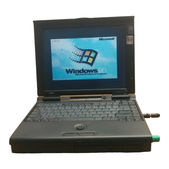
P r e f a c e PREFACE The LifeBook 700 Series from Fujitsu ™ Corporation is a powerful notebook computer. It is powered by an Intel Pentium microproc- ® essor with MMX technology, has a built-in ™ color display, a CD-ROM drive and brings the computing power of desktop personal computers (PCs) to a p ortable environment. - Page 11 L i f e B o o k 7 0 0 S e r i e s f r o m F u j i t s u Figure P-1 LifeBook 700 Series with Both Fujitsu and Third Party Options...
- Page 12 S et tin g U p Yo u r Li f eB oo k 7 0 0 Ser ie s Unpacking ....2 Overview of LifeBook 700 Series Features .
-
Page 13: Section One
SETTING UP YOUR LIFEBOOK 700 SERIES FROM FUJITSU This section describes how to set up your LifeBook 700 Series from Fujitsu. We strongly recommend that you read it before using your notebook – even if you are already familiar with notebook computers. - Page 14 Figure 1-3 Device Adapter for Multi-function Bay 2 Figure 1-4 Floppy Disk Drive S e t t i n g U p Y o u r L i f e B o o k 7 0 0 S e r i e s Once you have checked and confirmed that your notebook system is complete, connect the AC adapter and follow the instructions on page...
-
Page 15: Component Identification
S e c t i o n O n e Full audio and video features: 16-bit SoundBlaster-compatible sound chip. 3D-Stereo for multiple speaker effect. Zoomed Video support for full motion video acceleration. Built-in stereo speakers. Built-in mono microphone. Stereo line in jack. Stereo headphone jack. - Page 16 S e t t i n g U p Y o u r L i f e B o o k 7 0 0 S e r i e s Display Panel Latch Display Panel Status Indicator Panel Brightness Control Keyboard Contrast Control (Model 735Dx Only) Built-in Microphone ErgoTrac Pointing Device Suspend/Resume button Multi-function Bay 1 Closed Cover Switch Figure 1-6 LifeBook 700 Series with Display Open...
-
Page 17: Top And Front Components
The brightness control adjusts the overall inten- sity of the display panel back lighting. (Figure 1-6.) Contrast Control (Model 735Dx only) The contrast control (located just below the brightness control) sets the ratio of the intensi- ty of the light to dark areas of the display. -
Page 18: Left Side Panel Components
Lithium ion battery mounted in the device adapter for Multi-function Bay 2 (a second battery can be purchased separately for a dual battery configuration). Optional second 3.2GB hard drive (which must be purchased separately). 3.5" floppy disk drive mounted in the device adapter for Multi-function Bay 2. -
Page 19: Rear Panel Components
S e c t i o n O n e Power Switch This switch is the main power switch for your notebook. (Figure 1-8.) Right Speaker The built-in dual speakers output stereo sound from the notebook. (Figure 1-7 and Figure 1-8.) External Floppy Disk Drive Port A port for attaching an optional external floppy disk drive. - Page 20 C A U T I O N The internal modem is not intended for use with Digital PBX systems. Do not connect the internal modem to a digital PBX as it may cause serious damage to the internal modem or your entire note- book.
-
Page 21: Bottom Components
S e c t i o n O n e BOTTOM COMPONENTS Tilt Adjustment Feet These are a pair of feet which flip down and hold the back of the keyboard approximately 6° higher than the front when resting on a flat surface. -
Page 22: Data Security
To Connect the Optional Auto/airline Adapter 1. Plug the DC Output cable into the DC Power jack on the right side panel of your notebook. 2. Plug the auto/airline adapter plug into the cigarette lighter of a car or other vehicle with the ignition key in the On or the Accessories position or into the DC Power jack on an airplane seat. -
Page 23: Starting Your Notebook For The First Time
When you turn on your notebook for the first time it will display a Fujitsu lo go on the screen. If you do nothing the system will read the hard drive for the operating system software, flash the notebook configuration information on the... - Page 24 information you have entered and takes you on to the next screen. The C a n c e l button allows you to stop the setup process. If you stop the process your notebook will start up at the b eginning of the Windows 95 Setup Wizard.
-
Page 25: User Registration
There are two Fujitsu Welcome Center icons on your notebook desktop, one for use if you have a model 735Dx and the other for use if you have a model 755Tx or a model 765Tx. Be sure to use the correct icon or your product registration may be invalid. -
Page 26: Learning About Your Operating System And Application Software
LEARNING ABOUT YOUR OPERAT I N G SYSTEM AND APPLICATION SOFTWA R E Tutorials All operating systems and most application software have tutorials built-in. We highly rec- ommend that you step through your tutorial before you use an application even if you are familiar with the same application on a differ- ent machine,an earlier version of the applica- tion, or a similar product. - Page 27 Restarting the System ... . 25 Fujitsu Welcome Center ... 26 Batteries ....26 Integrated ErgoTrac Pointing Device .
-
Page 28: Section Two
(Figure 2-2.) You may need to adjust the brightness periodically for different Figure 2-1 Opening the Display Panel operating environments.(For model 735Dx only, you may also adjust contrast with a contrast control slider that is just below the brightness control.) -
Page 29: Adjusting The Keyboard Angle
ADJUSTING THE KEYBOARD ANGLE On the bottom of your notebook,near the back,are a pair of feet which flip down and hold the back of the keyboard about 6° higher than the front when resting on a flat surfa ce. They are designed to make it more comfortable to use the keyboard with your notebook. - Page 30 S e c t i o n T w o Power Battery Battery CD-ROM Identifier Charging Drive Access AC Adapter Battery Hard Drive Access Level Floppy Disk PC Card NumLk Scr Lk Drive Access Slot Identifier PC Card Access CapsLock Figure 2-3 Status Indicator Panel AC Adapter Indicator The AC Adapter indicator tells you whether the...
- Page 31 A small arrow icon (Battery Charging indica- tor) appears to the left of each of the Battery Level indicators and above the number (Battery identifier) if that battery is charging . The Battery Charging indicator flashes if the battery is too hot or too cold to charge. (Figure 2-3.) The Battery Charging indicators operate whether the power switch is Off or On.
- Page 32 S e c t i o n T w o P O I N T The Windows 95 CD automatic insertion function will periodically check for a CD installed in the drive, causing the CD- ROM Access indicator to flash. The CD automatic insertion function allows your system to automatically start a CD as soon as it is inserted in the drive and the...
-
Page 33: Power On
Floppy Disk Drive Access Indicator The Floppy Disk Drive Access indicator tells you a floppy disk drive is being accessed. The Floppy Disk Drive Access indicator will flash when your software tries to access a floppy disk even if no floppy disk drive is installed. PC Card Access Indicators The PC Card Access indicators tell you when an installed PC Card is being accessed. -
Page 34: Power Off
S e c t i o n T w o C A U T I O N After turning off your notebook, make sure that it has been Off at least 10 seconds before turning the power switch to On. If you do not you could cause a system error. -
Page 35: Restarting The System
C A U T I O N Never turn your notebook off while an application is running. Be sure to close all files, exit all applications and shut down your operating system prior to turning off the power with the power switch. If fil e s a re open when you turn the power off , you will lose any changes that have not been saved, and may cause disk erro r s . -
Page 36: Fujitsu Welcome Center
10 seconds may also cause an error when you start the next time. FUJITSU WELCOME CENTER The Fu j i t su Wel come Cen ter is an icon on yo u r Wi n dows 95 de s k top. Cl i cking on it gives yo u... - Page 37 C A U T I O N Actual battery life will vary based on screen brightness, applications, features, power management settings, battery condition, and other customer prefer- ences. CD-ROM drive or hard drive usage may also have a significant impact on battery life.
- Page 38 S e c t i o n T w o Shorted Batteries If your Status Indicator panel shows a shorted battery, check the installation for that battery by removing and re-installing it. If it still shows that it is shorted, replace it with a new battery. C A U T I O N A shorted battery is damaged and must be replaced so that it does not damage...
- Page 39 Low Battery State When the battery is running low, your note- book beeps about every 15 seconds and the Battery Level indicator(s) flash. If you do not respond to the low battery alarm,the batteries will continue to discharge until they are too low to operate.
-
Page 40: Integrated Ergotrac Pointing Device
S e c t i o n T w o Cursor Control Left Button Right Button INTEGRATED ERGOTRAC POINTING DEVICE The ErgoTrac pointing device is composed of a small joystick-like disc pointer control and two Cursor buttons located in front of the keyboard. The ErgoTrac pointing device has the function of a mouse,and moves the cursor around on the screen –... - Page 41 Left Click Left Double Click Figure 2-7 Clicking Clicking Clicking means pushing and releasing a button. To left-click move the screen cursor to the item you wish to select, press the left pointing device button once,and then immediately release it. To right-click,move the mouse cursor to the it em you wish to select, press the right pointing device button once,and then immediately...
-
Page 42: Using The Keyboard
S e c t i o n T w o Pointers – This lets you set up the size and shape of the cursor for different functions. Motion – This lets you set up the relation of the speed of motion of your finger to the motion of the cursor and to enable a t railing tail for the cursor arrow. - Page 43 Numeric Keypad Certain keys on the keyboard perform dual functions as both standard character keys and numeric keypad keys.Figure 2-9 highlights these keys. To switch into numeric keypad mode, press the NumLk/Scr Lk while holding down the Shift key. You can now enter numerals 0 through 9, perform addition ( + ), subtraction ( –...
-
Page 44: Volume Control
S e c t i o n T w o VOLUME CONTROL All system and application functions have mul- tiple volume controls which interact with each other. There is the hardware volume control on the right side panel o f your notebook. There is a volume control in the ESS AudioRack, your operating system Sound Control panel and any other application with sound. - Page 45 Figure 2-10 Loading/Ejecting a Floppy Disk P O I N T When there is no floppy disk in the drive, the Eject button is flush with the front of your notebook. U s i n g Y o u r L i f e B o o k 7 0 0 S e r i e s Ejecting a Floppy Disk To eject a disk, check that the Floppy Disk Drive Access indicator is Off, (see pages 20...
-
Page 46: Cd-Rom Drive
S e c t i o n T w o C A U T I O N Formatting a previously used floppy disk is an effective method of clearing a disk as long as you realize that ALL the infor- mation on the disk will be erased. - Page 47 Loading a CD • Make sure that the angle adjustment feet on the bottom of the notebook are folded against the bottom of the notebook. • Make sure there is power to your notebook. • Push, gently but firmly, and release the eject button on the front of the CD-ROM drive to open the CD-ROM holder tray, the tray will come out a short distance.
-
Page 48: Hard Drive
S e c t i o n T w o HARD DRIVE The internal hard drive capacity is dependent on which model you are using. See Appendix A (pages 147-166) for model information. If you are using the optional second hard drive for the first time since you installed it, you can get your notebook to recognize it by opening the Windows 95 Control Panel and opening Add... - Page 49 Technologies,and the Windows 95 Control panel. If no settings have been made in the PowerPanel or Windows 95 Control panel then the BIOS settings will be used. The PowerPanel and Windows 95 Control panel have been pre-set at the factory and will be active unless you disable them.
- Page 50 S e c t i o n T w o P O I N T Disabling the Suspend/Resume button prevents it from being used to put your notebook in Suspend or Save-to-Disk mode. The resume function of the button cannot be disabled. (See the Power Savings Menu of the BIOS setup utility, pages 81-87, for more information.) C A U T I O N...
- Page 51 The profiles are groups of system settings designed to fit power operation to specific user operating conditions. The activations are short- cut ways to turn on specific power management features of your notebook. The profile choices are: Maximum Battery Life. Maximum Performance.
- Page 52 S e c t i o n T w o Maximum Battery Life Profile The Ma x i mum Ba t tery Life profile is a factory i n s t a ll ed com bi n a ti on of ti m eo uts and other power savi n gs para m eters ch o s en as the set ti n gs that wi ll produ ce the lon gest po s s i ble battery life .
- Page 53 System Save-to-Disk Activation Clicking on the Save-to-Disk button or select- ing System Save to Disk on the PowerPanel menu will put your notebook in Save-to-Disk mode. Your notebook will be left in the Windows 95 pseudo-off state. If the power switch is not turned off your notebook can be restarted by pressing the Suspend/Resume but- ton which will cause the system memory to...
- Page 54 S e c t i o n T w o C A U T I O N Loss of all power sources, including batteries, while in the Suspend mode will cause lost data and inability to re t u rn to operation with the Suspend/ Resume button.
- Page 55 P O I N T Save-to-Disk mode requires allocating a significant amount of hard drive capacity for saving all system memory, which reduces your usable disk space. When you purchase your notebook it will have space allocated for the memory installed. If you upgrade the original system by adding a memory upgrade module with- out changing the size of your Save-to-...
-
Page 56: Internal Modem
S e c t i o n T w o Resume button. This parameter is enabled and disabled in the BIOS setup utility. Windows 95 Control Panel The Power icon in the Wi n dows 95 Con tro l Pa n el all ows you to en a ble or disable all the power managem ent set ti n gs wh i ch can be made f rom the de s k top. -
Page 57: Pre-Installed Software
C A U T I O N Do not move either device during communication as it may interrupt data transmission. C A U T I O N Be careful not to scratch the infrared port lens. Scratches, dirt or other surface marks can effect operation. - Page 58 S e c t i o n T w o ESS AudioRack The control of the AudioRack player software (AudioRack32) resembles the front panels of a rack of stereo equipment and is operated in much the same way. There is also AudioRack recorder software (AudioRecorder).Online help screens are accessible from the AudioDrive panel of AudioRack32, click on the Help button...
- Page 59 P O I N T For optimum speakerphone performance: Speak clearly. Limit background noise. Speak facing the keyboard from about one (1) foot away. McAfee VirusScan Running your McAfee VirusScan program after loading data or programs from a floppy disk, CD-ROM,modem data transfer, or infrared data transfer is a precaution that will protect the data on your hard drive from contamina-...
- Page 60 Con f iguri ng You r Lif eBo o k 7 00 Series Boot Sequence ....52 Identifying the Drives ... . . 52 BIOS Setup Utility .
-
Page 61: Section Three
BOOT SEQUENCE Each time you power up or restart your LifeBook 700 Series,it goes through a quiet boot sequence that displays a Fujitsu logo until your operating system is loaded. During quiet boot, your notebook is performing a standard boot sequence including a Power On Self Test (POST). -
Page 62: Bios Setup Utility
To do this: 1. Allow the system to start booting. 2. As soon as the Fujitsu logo appears on the screen, press the F2 key. 3. The Main menu of the setup utility then appears with the current settings of the parameters displayed. - Page 63 S e c t i o n T h r e e P O I N T If your data security settings require it, you may be asked for a password before the Main menu will appear. Entering the Setup Utility After a Configuration Change or System Failure If there has been a change in the syst em config- uration that does not agree with the parameter...
-
Page 64: Navigating Through The Setup Utility
NAVIGATING THROUGH THE SETUP UTILITY The BIOS setup utility consists of six menus; MAIN,ADVANCED, SECURITY, POWER SAVINGS, BOOT and EXIT. The remainder of Section Three explains each menu in turn including all submenus and setup items. The following procedures allow you to navigate the setup utility menus: 1. -
Page 65: Main Menu - Setting System Parameters
S e c t i o n T h r e e MAIN MENU – SETTING STANDARD SYSTEM PARAMETERS The Main Menu allows you to set or view the current system parameters. Follow the instruc- tions for Navigating Through The Setup Utility to make any changes. - Page 66 Table 3-1 Fields, Options and Defaults for the Main Menu Menu Field Options System Time — System Date — Diskette A 1.44Mb, 3.5”; Disabled IDE Adapter 0 Master Selects the IDE Adapter 0 Master submenu. IDE Adapter 1 Master Selects the IDE Adapter 1 Master submenu.
- Page 67 S e c t i o n T h r e e Table 3-1 Fields, Options and Defaults for the Main Menu Menu Field Options Boot Options Selects the Boot Options submenu System Memory Extended Memory Default Description Pressing the Enter key selects the Boot Options submenu. Displays the size of system memory, which is detected 640 KB automatically and cannot be changed by the setup utility.
- Page 68 IDE Adapter – Submenu The IDE Adapter 0 Master or IDE Adapter 1 Master submenus are identical for hard drives. They have the capacity displayed at the top of the screen as well as on Main menu. Follow the instructions for Navigating Through the Setup Utility to make any changes.
- Page 69 S e c t i o n T h r e e Table 3-2 Fields, Options and Defaults for the IDE Adapter Submenu Menu Field Options Autotype Fixed Disk: [Press Enter] Type: Auto; None;CD; User; 1-14; Rsvr; 16-39 Cylinders: (Available to A number between 0 change only when and 65,535.
- Page 70 Table 3-2 Fields, Options and Defaults for the IDE Adapter Submenu Menu Field Options Head: (Available to A number between 1 and 16. change only when Type = User. Displayed for Type = Auto when a hard drive has been detected and Type = any number.) Sectors/Track: (Available to A number between 0 and 63.
- Page 71 S e c t i o n T h r e e Table 3-2 Fields, Options and Defaults for the IDE Adapter Submenu Menu Field Options Multi-Sector Transfers: Disabled; 2; 4; 8;16. (Available to change only when Type =User, None, Rsvr, or a number.
- Page 72 C A U T I O N A bootable CD-ROM may have either a floppy disk format or a hard drive format. When the bootable CD-ROM is used the drive allocations change automatically without changing the BIOS setup. If a floppy disk format CD-ROM is used the CD-ROM becomes Drive A.
- Page 73 S e c t i o n T h r e e Table 3-3 shows the names of the menu fields for the Boot Options submenu,all of the options for each field,the default settings and a description of the field’s function and any special information needed to help understand the field’s use.
-
Page 74: Advanced Menu - Setting Device Controls
ADVANCED MENU – SETTING DEVICE FEATURE CONTROLS The Advanced Menu allows you to: Set the I/O addresses for the serial and parallel ports. Set the communication mode for the parallel port. Set an audio function I/O address,interrupt level and DMA channel. Select between the display panel and an external CRT display. - Page 75 S e c t i o n T h r e e Table 3-4 Field Names, Options and Defaults for the Advanced Menu Menu Field Options Integrated Peripherals – Keyboard/Mouse Features – Audio Features – Video Features – Default Description –...
- Page 76 C A U T I O N I/O addresses, DMA channels and I n t e rrupt levels can be entered in various ways, including via the BIOS setup utility, the control software for the I/O device, or the hard w a re. If any two ports or devices, serial or parallel, have the same I/O a d d ress assigned your notebook will not function norm a l l y.
- Page 77 S e c t i o n T h r e e P O I N T All I/O addresses in Table 3-5 are in hexadecimal. Table 3-5 Fields, Options and Defaults for the Integrated Peripherals Submenu Menu Field Options COM Port: 3F8, IRQ 4;...
- Page 78 Table 3-5 Fields, Options and Defaults for the Integrated Peripherals Submenu Menu Field Options LPT Port: 278.IRQ 7; 378,IRQ 7; 3BC,IRQ 7; 278,IRQ 5; 378,IRQ 5; 3BC,IRQ 5; Disabled LPT Mode: Bi-Directional; ECP, DMA CHANNEL 1; ECP, DMA CHANNEL 3; Output Only Diskette Controller: Enabled;...
- Page 79 S e c t i o n T h r e e Table 3-5 Fields, Options and Defaults for the Integrated Peripherals Submenu Menu Field Options PCI IRQ Routing: Disabled; Auto select; IRQ3; IRQ4;IRQ5; IRQ7; IRQ9;IRQ10; IRQ11 Internal Modem: Enabled; Disabled Default Description Auto select...
- Page 80 L i f e B o o k 7 0 0 S e r i e s f r o m F u j i t s u C o n f i g u r i n g Y o u r L i f e B o o k 7 0 0 S e r i e s Keyboard/Mouse Features Submenu The Keyboard/Mouse Features submenu is for setting the parameters of the integrated and...
- Page 81 S e c t i o n T h r e e Table 3-6 Fields, Options and Defaults of the Keyboard/Mouse Submenu of the Advanced Menu Menu Field Options Numlock: Off;On; Auto Keyboard/Mouse Enabled; Disabled Hot Plug: Internal Pointing Device: Auto Disabled;...
- Page 82 L i f e B o o k 7 0 0 S e r i e s f r o m F u j i t s u C o n f i g u r i n g Y o u r L i f e B o o k 7 0 0 S e r i e s Audio Features Submenu The Audio Features Submenu is for setting the features of the built-in audio functions.
- Page 83 S e c t i o n T h r e e Table 3-7 Fields, Options and Defaults of the Audio Features Submenu of the Advanced Menu Menu Field Options Audio Base Address: 220; 240;260; 280; Disabled Audio FM Base Address: 388;38C;...
- Page 84 L i f e B o o k 7 0 0 S e r i e s f r o m F u j i t s u C o n f i g u r i n g Y o u r L i f e B o o k 7 0 0 S e r i e s Video Features Submenu The Video Features Submenu is for setting the display parameters.
- Page 85 S e c t i o n T h r e e Table 3-8 Fields, Options and Defaults for the Video Features Submenu of the Advanced Menu Menu Field Options Display: Flat-Panel; CRT; Simultaneous Compensation: Enabled; Disabled Exiting from the Advanced Menu When you have finished setting the parameters on the Advanced Menu, you can either exit from setup utility or move to another menu.
-
Page 86: Security Menu - Setting Passwords
L i f e B o o k 7 0 0 S e r i e s f r o m F u j i t s u C o n f i g u r i n g Y o u r L i f e B o o k 7 0 0 S e r i e s SECURITY MENU –... - Page 87 S e c t i o n T h r e e P O I N T If you set a password, write it down and keep it in a safe place. If you forget the password you will have to contact your support representative to regain access to your secured functions and data.
- Page 88 Table 3-9 Fields, Options and Defaults for the Security Menu Menu Field Options Supervisor Password is: – User Password is: – Set Supervisor Password: [Press Enter] Diskette access: All; Supervisor Only Set User Password: [Press Enter] C o n f i g u r i n g Y o u r L i f e B o o k 7 0 0 S e r i e s Default Description Disabled...
- Page 89 S e c t i o n T h r e e Table 3-9 Fields, Options and Defaults for the Security Menu Menu Field Options Password on Boot: Enabled; Disabled Power Management Enabled; Disabled Security: Fixed Disk Boot Sector: Normal; Write Protect P O I N T Boot Sector Protection must be set to Normal to load or upgrade an...
-
Page 90: Power Savings Menu - Setting Power Management Feature Controls
POWER SAVINGS MENU – SETTING POWER MANAGEMENT FEATURE CONTROLS The Power Savings menu allows you to set and change the power management parameters. Follow the instructions for Navigating Through the Setup Utility to make any changes. (See page 55.) Table 3-10 shows the names of the menu fields for the Power Savings menu,all of the options for each field,the default settings and a descrip- tion of the field’s function and any special... - Page 91 S e c t i o n T h r e e Table 3-10 Fields, Options and Defaults for the Power Savings Menu. Menu Field Options Power Savings: Customize; Maximum Performance; Maximum Battery Life; Off Hard Disk Timeout: 30 seconds to 20 minutes;Off Video Timeout: 30 seconds to 20 minutes;Off Default...
- Page 92 Table 3-10 Fields, Options and Defaults for the Power Savings Menu. Menu Field Options Idle Mode: On; Off Standby Timeout: 1 minute to 16 minutes;Off Auto Suspend Timeout: 5 to 60 minutes;Off C o n f i g u r i n g Y o u r L i f e B o o k 7 0 0 S e r i e s Default Description Turns on and off the slow down of the CPU during periods of...
- Page 93 S e c t i o n T h r e e Table 3-10 Fields, Options and Defaults for the Power Savings Menu. Menu Field Options Suspend Mode: Suspend; Save-to-Disk P O I N T When resuming from a Save-to-Disk suspension there will be a delay while the contents of system memory and operating parameters are loaded from the hard drive.
- Page 94 Table 3-10 Fields, Options and Defaults for the Power Savings Menu. Menu Field Options Resume On Time: On; Off Resume Time: – Advanced Features – Factory Installed Values for Power Saving Profiles Profile Hard Disk Timeout Customize Maximum Performance Maximum Battery Life 30 Seconds C o n f i g u r i n g Y o u r L i f e B o o k 7 0 0 S e r i e s Default...
- Page 95 S e c t i o n T h r e e Advanced Features Submenu The Advanced Features submenu is for setting some non-time related power saving parame- ters. Follow the instructions for Navigating Through the Setup Utility to make any changes. (See page 55.) Table 3-11 shows the names of the menu fields for the Video Features submenu,all of the...
- Page 96 Table 3-11 Fields, Options and Defaults for the Advanced Features Submenu of the Power Savings Menu Menu Field Options SUS/RES Switch: Enabled; Disabled Lid Closure Suspend: Enabled; Disabled AMU CPU Idle Mode: Low Power; Standard LCD Backlight Mode: Low Power; Standard Serial Mouse Activity: Enabled;...
-
Page 97: Boot Menu
S e c t i o n T h r e e BOOT MENU – SELECTING THE OPERATING SYSTEM SOURCE The Boot Menu is used to select the order in which the BIOS searches sources for the operating system. Table 3-12 shows the names of the menu fields for the Boot menu,all of the options for each field,the default settings and a description of the field’s function and any special information... - Page 98 Table 3-12 Fields, Options and Defaults for the Boot Menu. Menu Field Options 1. Hard Drive – 2. Diskette Drive – 3.CD-ROM Drive – Exiting from Boot Menu When you have finished setting the search sequence order with the Boot menu, you can either exit from the setup utility or move to another menu.
-
Page 99: Exit Menu - Leaving The Setup Utility
S e c t i o n T h r e e EXIT MENU – LEAVING THE SETUP UTILITY The Exit Menu is used to leave the setup utility. Follow the instructions for Navigating Through the Setup Utility to make any changes. (See page 55.) Table 3-13 shows the names of the menu fields for the Exit menu,all of the options for each... - Page 100 Table 3-13 Fields, Options and Defaults for the Exit Menu. Menu Field Options Save Changes and Exit: – Discard Changes and Exit: – Get Default Values: – C o n f i g u r i n g Y o u r L i f e B o o k 7 0 0 S e r i e s Default Description –...
- Page 101 S e c t i o n T h r e e Table 3-13 Fields, Options and Defaults for the Exit Menu. Menu Field Options Load Previous Values: – Save Changes: – Default Description – Selecting Load Previous Values will load the values in BIOS memory for all menu fields.
-
Page 102: Setting Up Your Save-To-Disk File Allocation
1. Restart your notebook in MS-DOS mode. 2. At the DOS prompt type CD C:\Fujitsu 3. Type PHDISK. 4. Press the Enter key. 5. The screen will display the amount disk space needed to perform the Save-to-Disk function with the current memory configuration and... - Page 103 S e c t i o n T h r e e 5. The utility will remove the space allocation for the Save-to-Disk function and free that space for other use. To create a space allocation for the Save-to-Disk function, do the following: 1.
- Page 104 U s e r I n s t a l l a b l e F e a t u r e s Multi-function Bay Devices ..97 PC Cards ....103 Parallel Port Devices .
-
Page 105: Section Four
S e c t i o n F o u r SECTION FOUR USER INSTALLABLE FEATURES Your LifeBook 700 Series has a number of user installable features: PC Card slots in the left side panel of your notebook allow you to install PC Cards, IC memory cards (SRAM card) or Zoomed Video cards (Slot 0 only). -
Page 106: Multi-Function Bay Devices
Floppy Bay 1 Modules Disk Drive Lithium ion Battery MULTI-FUNCTION BAY DEVICES The bays in the front panel of your notebook accommodate the CD-ROM drive, the floppy disk drive,the Lithium ion batteries (a second battery is optional) or the optional second hard drive. - Page 107 S e c t i o n F o u r 3.5" floppy disk drive installed in Device Adapter for Multi-function Bay 2. (Adapter included with your notebook.) Lithium ion battery installed in Device Adapter for Multi-function Bay 2. (Adapter included with your notebook.) The Lithium ion battery included with your notebook can power your notebook from either bay.
- Page 108 Multi-function Bay 2 Release Button Figure 4-3 Removing and Installing a Device in Multi-function Bay 2 To Install or Remove a Device in Multi- function Bay 2. 1. Close all files and exit all applications. 2. Turn off power to your notebook, close the display and remove the AC adapter.
- Page 109 S e c t i o n F o u r 3. Set the device adapter for Multi-function Bay 2 on top of the Multi-function Bay 1 device and adjust until the finger ridge shows through the hole in the device adapter for Multi-function Bay 2,and the alignment pins on the Multi-function Bay 1 device fit in the small round holes of the device adapter for...
- Page 110 C A U T I O N The CD-ROM Drive must be installed or removed with the power off. Optional Second Hard Drive The optional second hard drive is durable but you must treat it with care.Please pay attention to the following points: The drive rotates the disk at very high speed.
- Page 111 S e c t i o n F o u r The battery may be installed singly in either bay, using the device adapter for Multi-function Bay 2. With the purchase of an additional bat- tery, batteries may be installed in a dual config- uration, one in each bay.
-
Page 112: Pc Cards
C A U T I O N The floppy disk drive must be installed or removed with the power off. PC CARDS PC Cards perform a wide variety of functions, and are ideal for mobile computers. Some available PC Cards: Fax/data modem cards (Type II). - Page 113 S e c t i o n F o u r Installing PC Cards in Your Notebook PC cards are install ed in the PC Ca rd slot in the l eft side panel of your noteboo k . Some PC Ca rd s wi ll not work wh en all po s s i ble devi ces are en a bl ed .
-
Page 114: Parallel Port Devices
From the PC Card Properties Window: 3. Select the card to be removed and click on the S t o p button. 4. Verify that the You can safely remove your cardmessage appears. 5. If thedevice cannot be removed message appears,save all files, close all applications, and exit Windows 95 then shut- off the power with the power switch. -
Page 115: Telephone Lines
S e c t i o n F o u r TELEPHONE LINES To attach a telephone line to the internal modem open the rear panel connector cover or with the cover closed slide the panel in the con- nector cover slightly opened to reveal the RJ-11 jack.Plug one end of the telephone cable into the telephone line outlet.Orient the telephone cable with the release latch on the connector... -
Page 116: External Installation Of The Floppy Disk Drive
External Floppy Disk Drive Port External Floppy Disk Drive Connector Cover Connector Release Button Connector Release Button External Floppy Disk Drive Figure 4-10 External Installation of a Floppy Disk Drive. U s e r I n s t a l l a b l e F e a t u r e s EXTERNAL INSTALLATION OF A FLOPPY DISK DRIVE... -
Page 117: Memory Upgrade Module
S e c t i o n F o u r Figure 4-11 Opening the Memory Upgrade Compartment Figure 4-12 Removing a Memory Upgrade Module MEMORY UPGRADE MODULE Your notebook has 16MB or 32MB of installed SDRAM. To increase your memory capacity you may install a memory upgrade module in the memory upgrade compartment in the bot- tom of your notebook. - Page 118 C A U T I O N The memory upgrade module can be severely damaged by electro-static dis- charge (ESD). Be sure you are properly grounded when handling and installing the module. 7. Align the connector edge of the memory upgrade module with the connector slot in the compartment.
- Page 119 1. Turn on power using the power switch. 2.Enter the setup utility by pressing the F2 key as soon as the Fujitsu logo appears on the screen. (See pages 53-54.) 3. The System Memory and the Extended...
-
Page 120: Landock
If the total memory displayed is not what you believe it should be, check that your memory upgrade module is properly installed. If it is properly installed and the capacity is not cor- rectly recognized,see the Troubleshooting Section starting on page 119. Undock Request Button RJ-11 Jack RJ-45 Jack... - Page 121 S e c t i o n F o u r Figure 4-15 Installing a LANdock 6. Set your notebook on the Docking Station Leveler, making sure that the Alignment pins on the leveler (Figures 4-13 and 4-16) fit into the Docking Alignment receptacles in the bottom of your notebook (Figure 1- 10 on page 9).
- Page 122 P O I N T If the notebook power switch is turned off it is always safe to undock. You do not have to turn on your notebook and use the Eject PC feature. C A U T I O N The RJ-11 connector on the rear of your docking device comes with a protective cover to keep the connector clean.
- Page 123 Select the < s e t t i n g s > tab and change the resolution to 800 x 600 pixels. f. Change the monitor setting to Laptop Display Panel (800 x 600). g. Click on the < O K > button to activate the new display settings.
-
Page 124: Port Replicator
PORT REPLICATOR The Port Replicator is installed and operated exactly like the LANdock but adds no addi- tional functions to your notebook. Follow the LANdock instructions for installation and use. Undock Request Button RJ-11 Jack Ready to Undock LED Docked LED DC Power Jack PS/2 Mouse Port PS/2 Keyboard Port... - Page 125 T o u b l e s h o o t i n g Identifying the Problem ... 118 Specific Problems ....119 Power On Self Test Messages .
-
Page 126: Section Five
8. If you have tried the solutions suggested in Specific Problems without success, contact your support representative: toll free 1-800- 8FUJITSU (1-800-838-5487), FAX 1-800- 935-1789,e-mail 8fujitsu@fpc.fujitsu.com, Web Site http://www.8fujitsu.com. Before you place the call, you should have the following information ready so that the... -
Page 127: Specific Problems
If your are an experienced computer user you may find it useful,however, it is intended primarily to help your Fujitsu support representative better serve you. When you call for help your support representative may ask you to setup your note- book for modem operation. - Page 128 S e c t i o n F i v e Problem Audio Problems There is no sound coming from the built-in speakers. CD-ROM Drive Problems Notebook fails to recognize CD-ROM. Possible Cause 1. The volume knob is turned too low. 2.
- Page 129 Problem The CD-ROM Access indicator on the Status Indicator panel blinks at regular intervals when no CD is in the tray or the CD-ROM drive is not installed. Docking Problems Notebook does not turn on when installed in Docking Station. T r o u b l e s h o o t i n g Possible Cause 5.
- Page 130 S e c t i o n F i v e Problem Floppy Disk Drive You cannot access your floppy disk. Possible Cause 2. Notebook is not properly seated in the LANdock. 1. Security is set to protect access to floppy disk data.
- Page 131 Problem Hard Drive Problems You can not access your hard drive. Keyboard or Mouse Problems The built-in keyboard does not seem to work. T r o u b l e s h o o t i n g Possible Cause 1.
- Page 132 S e c t i o n F i v e Problem You have installed an external keyboard You have connected an external keyboard or a mouse and it seems to be locking up the system. Memory Problems Your power on screen or Main menu of the BIOS setup utility information does not show the correct amount of installed memory.
- Page 133 Problem Modem Problems Messages about modem operation. Parallel, Serial,and USB Device Problems You have installed a parallel-p ort device, a serial-port device or a USB device. Your notebook does not recognize the device, or the device does not seem to work properly. T r o u b l e s h o o t i n g Possible Cause 2.
- Page 134 S e c t i o n F i v e Problem C A U T I O N Due to ongoing changes in USB technology and standards, not all USB devices and/or drivers are guaranteed to work. PC Card Problems A card inserted in the PC Card slot does not work or is locking up the system.
- Page 135 Problem Power Failures You turn on your notebook and nothing seems to happen. T r o u b l e s h o o t i n g Possible Cause 1. The installed primary battery is completely discharged,there is no optional second battery installed and there is no Power adapter (AC or auto/airline) installed.
- Page 136 S e c t i o n F i v e Problem Possible Cause 3. The primary battery is installed but is completely discharged, there is no optional second battery installed and the Power adapter (AC or auto/airline) has no power from the AC outlet,airplane seat jack, or the car’s 4.
- Page 137 Problem T r o u b l e s h o o t i n g Possible Cause 5. Power switch is already in the On position. 6. There is no battery installed and there is no Power adapter (AC or auto/airline) installed. 7.
- Page 138 S e c t i o n F i v e Problem Your notebook turns off all by itself. Possible Cause 8. The battery or batteries are low. 1. The power management parameters are set for auto timeouts which are too short for your operating needs.
- Page 139 Problem Your notebook won’t work on battery alone. T r o u b l e s h o o t i n g Possible Cause 3. You have a battery failure. 4. Your Power adapter has failed or lost it’s power source. 1.
- Page 140 S e c t i o n F i v e Problem The batteries seem to discharge too quickly. Shutdown and Startup Problems The Suspend/Resume button does not work. Possible Cause 1. You are running an application which uses a great deal of power because of frequent hard drive access or CD-ROM access,use of a modem PC Card or of a LAN PC Card.
- Page 141 3. Close all applications, and try the button again. 1. Set the operating source by pressing the Esc key while the Fujitsu logo is on screen or use the F2 key and enter the setup utility and adjust the source settings from the Boot menu on page 89.
- Page 142 S e c t i o n F i v e Problem An error message is displayed on the screen during the notebook turn on (boot) sequence. Your notebook appears to change setup parameters when you start it. Video Problems The built-in display is blank when you turn on your notebook.
- Page 143 Problem The display goes blank by itself after you have been using it. T r o u b l e s h o o t i n g Possible Cause 3. The angle of the display and the brightness settings are not adequate for your lighting conditions.
- Page 144 S e c t i o n F i v e Problem The Built-in Display does not close. The Built-in Display has bright or dark spots. The application display uses only a p ortion of your screen and is surrounded by a dark band. Possible Cause 3.
- Page 145 Problem You have connected an external monitor and it does not come on. Miscellaneous Problems An error message is displayed on the screen during the operation of an application. T r o u b l e s h o o t i n g Possible Cause 1.
-
Page 146: Power On Self Test Messages
S e c t i o n F i v e POWER ON SELF TEST MESSAGES The following is an alphabetic list of error-and- status messages that Phoenix BIOS and/or your operating system can generate and an explana- tion of each message.Error messages are marked with an *. - Page 147 This means that the fl oppy disk drive type iden- tified in your Setup Utility does not agree with the type detected by the Power On Self Test. Run the Setup Utility to correct the inconsistency. *Invalid NVRAM media type Problem with NVRAM access.
- Page 148 S e c t i o n F i v e loads default values and offers to run Setup. If the failure was caused by incorrect values and they are not corrected,the next boot will likely fail also. If using the default settings does not allow you to complete a successful boot sequence, you should turn off the power with the Power Switch and contact your...
-
Page 149: Emergency Cd-Rom Tray Release
Figure 5-1 Emergency CD-ROM Tray Release EMERGENCY CD-ROM TRAY RELEASE If for some reason the eject button fails, you can open the CD-ROM tray with a paper clip or similar tool inserted into the eject hole in the far right side of the front of the tray. Straighten one side of a paper clip and push it gently into the hole. - Page 150 S e c t i o n S i x C a r e a n d M a i n t e n a n c e Care and Maintenance ... 144 Caring for Your Notebook.
-
Page 151: Section Six
S i x SECTION SIX CARE AND MAINTENANCE If you use your LifeBook 700 Series from Fujitsu carefully, you will increase its life and reliability. This section provides some tips for looking after the notebook and the battery packs. CARING FOR YOUR NOTEBOOK The LifeBook 700 Series is a durable but sensitive electronic device. -
Page 152: Increasing Battery Life
INCREASING BATTERY LIFE To increase battery life: 1. Power your notebook through the AC or optional auto/airline adapter whenever possible. 2. If your notebook is running on battery power all day, connect it to the AC adapter overnight to recharge the battery. 3. - Page 153 Warranty ....148 LifeBook 735DX Specific a t i o n s ..148 LifeBook 755TX Specific a t i o n s ..151 LifeBook 765TX Specific a t i o n s .
-
Page 154: Appendix A Specifications
Floppy Disk Drive One modular 3.5" floppy disk drive which accommodates a 1.44MB or a 720KB floppy disk, Fujitsu Model FPCFDD03. One optional external floppy disk drive, Fujitsu Model FPCFD02. Hard Drive One factory installed 1.6GB, 2.5" (12.7 mm) fixed hard drive unit. - Page 155 A p p e n d i c e s Video MPEG-1 video data decompression software. Zoomed Video support via PC Card Slot 0. Device Adapter for Bay 2 Device adapter for Bay 2, Fujitsu Model FPCBYA01. Pre-Installed Software Microsoft Windows 95. LapLink by Traveling Software.
- Page 156 CD and hard drive access) in about fifteen (15) hours. AC Adapter Autosensing 100-240V AC,43W, supplying 16V DC to the Notebook, Fujitsu Model FPCAC05 which includes an AC cable. Optional Auto/Airline Adapter Autosensing 12/24V DC,43W supplying 16V DC to the Notebook, Fujitsu Model FPC- CAA02.
-
Page 157: Lifebook 755Tx Specifications
256 Bytes CMOS-RAM with back-up battery. Video RAM 2MB EDO RAM. Mass Storage Floppy Disk Drive One modular 3.5" floppy disk drive which accommodates a 1.44MB or a 720KB floppy disk, Fujitsu Model FPCFDD03. One optional external floppy disk drive, Fujitsu Model FPCFDA02. - Page 158 One IrDA compatible infrared port (4 Mbps). Video MPEG-1 video data decompression software. Zoomed Video support via PC Card Slot 0. Device Adapter for Bay 2 Device adapter for Bay 2, Fujitsu Model FPCBYA01. Pre-Installed Software Microsoft Windows 95. LapLink by Traveling Software.
- Page 159 (notebook Off or in Suspend mode) in about 5 hours.Standard charge (normal use with limit- ed CD and hard drive access) in about fifteen (15) hours. AC Adapter Autosensing 100-240V AC, 43W, supplying 16V DC to the notebook, Fujitsu Model FPCAC05 which includes an AC cable.
-
Page 160: Lifebook 765Tx Specifications
A p p e n d i c e s Optional Auto/Airline Adapter Autosensing 12/24V DC,43W supplying 16V DC to the Notebook, Fujitsu Model FPCCAA02. Power Management Save-to-Disk, Suspend, Idle and Standby power savings modes. When the battery is fully charged the computer can remain in suspend mode for approximately 24 hours or more. - Page 161 Floppy Disk Drive One modular 3.5" floppy disk drive which accommodates a 1.44MB or a 720KB floppy disk, Fujitsu Model FPCFDD03. One optional external floppy disk drive, Fujitsu Model FPCFDD02. Hard Drive One factory installed 3.2GB, 2.5" (12.7 mm) fixed hard drive unit.
- Page 162 External Mouse Support PS/2 compatible. Power Batteries One modular Lithium ion battery, Fujitsu Model FPCBP11. Rechargeable,10.8V, 3300 mAh. Operating time of up to 3 hours. Rapid charge (notebook Off or in Suspend mode) in about three (3) hours. Standard charge (normal use with limited CD and hard drive access) in about nine (9) hours.
-
Page 163: Approvals
CD and hard drive access) in about fifteen (15) hours. AC Adapter Autosensing 100-240V AC,43W, supplying 16V DC to the notebook, Fujitsu Model FPCAC05 which includes an AC cable. Optional Auto/Airline Adapter Autosensing 12/24V DC,43W supplying 16V DC to the notebook, Fujitsu Model FPCCAA02. - Page 164 Stereo Headphone. Microphone. Stereo Line In. The LANdock is powered from a power adapter which is included with the LANdock, Fujitsu Model FPCAC06. C A U T I O N The AC adapter for the LANdock and the Port Replicator is not the same as the one for your notebook.
-
Page 165: Appendix B Glossary
Appendix B Glossary AC Adapter A device which converts the AC voltage from a wall outlet to the DC voltage ne eded to power your Computer. Active-Matrix Display A type of technology for making flat-panel dis- plays which has a transistor or similar device for every pixel on the screen. - Page 166 A p p e n d i c e s CMOS RAM Complementary metal oxide semiconductor random access memory. This is a technology for manufacturing random access memory which requires very low levels of power to operate. COM Port Abbreviation for communication port. This is your serial interface connection.
- Page 167 Electro-Static Discharge. The sudden discharge of electricity from a static charge which has built-up slowly. Example: the shock you get from a doorknob on a dry day or the sparks you get from brushing hair on a dry day. Extended Memory All memory more than the 640KB recognized by MS-DOS as system memory.
- Page 168 A p p e n d i c e s Local Area Network. An interconnection of computers and peripherals within a single limited geographic location which can pass programs and data amongst themselves. Logical Block Addressing. A method of locating data stored on a disk.
- Page 169 Operating System A group of control programs that convert application commands,including driver pro- grams,into the exact form required by a spe- cific brand and model of microprocessor in order to produce the desired results from that particular equipment. Phase Alternation by Line. The standard for color television in Western Europe and most of Asia and Africa.
- Page 170 A p p e n d i c e s Random Access Memory. A hardware compo- nent of your computer that holds binary infor- mation (both program and data) as long as it has the proper power applied to it. RAM Module A printed circuit card with memory and associ- ated circuitry which allows the user to add...
- Page 171 Stroke (keyboard) The amount of travel of a key when it is pressed from resting to fully depressed. Suspend To make inoperative for a period of time. Your notebook uses various suspension states to reduce power consumption and prolong the charge of your battery.
-
Page 172: Index
I n d e x... - Page 173 I n d e x 3D-Stereo ..3-4,48,149, 152,155 AC adapter ..2-3,7,10-12,20-21,24-29 98-99,107,111, 121,150, 153,157-159 AC Adapter indicator ... 20-21 Access indicators .
- Page 174 CapsLock, ....6, 20,23 CardBus ..148-149,151-152,154-155,159 CD automatic insertion function . . 22,37,145 CD player....47-48 CD-ROM .
- Page 175 I n d e x DIMM ..148, 151,154, 160,108 Disk ..2-3,6-8,12,17, 20,23-25,34-36 41,43,45, 49,52-53,57,60,63, 69,79-80 82,84-85,93,95-98,100-103,107,111 115,119,122,138-139,141,148-149 151-152,154-163 Disk errors ....25 Diskette .
- Page 176 Feet ..9-10,19, 36-37,111,151,154,157 File transfers....4,46,48 Fixed Disk ... . 60,80,138-139 Floppy disk .
- Page 177 I n d e x Interrupt level ... 65, 68-69,74 IR, ..... 68,161 IrDA .
- Page 178 Mono microphone,..4,8,96, 105, 149, 152,155-156 Mouse ..4,8,30-33,66,71-72,78,87 95-96,106,111-113,115,119,123-124 149-150,152-153,155-156,158 Mouse cursor ....31,72 MPEG file player.
- Page 179 I n d e x Power Management ..6,26-27,29,38-42 45-46, 51,53, 78,80-81,130,135-136 145,150, 153-154,156-157 Power On Self Test..24,52, 54,64,80,110 117, 125, 134-135,138-139, 163, Power Savings ..6,38-40, 42,44,46 51,55,81-85,87, 130,132, 135,150, 154,157 Power source .
- Page 180 Security Menu ..11,51,77, 79-80,123,133 Serial port ....-9,68,87 95-96,105, 111,115, 125,164 Setup utility. . 6,11-12, 24,38-40,44-47,51-56 58-60,63-65,67,71, 73,75-77,79-81,86-87 89-92, 110,120-124,130,132-135,138-141 Shadow RAM ....164,140 Shortcut Menu.
- Page 181 I n d e x Telephone ..4,8,14,26,84,95-96,106 110,114, 149,152, 156,158 TFT ....3,153, 156,165 Theft Prevention Lock . 7, 95,106,151,154,157 Tilt Adjustment Feet .