
Related Manuals for Panasonic CZ-RC515UA


Summary of Contents for Panasonic CZ-RC515UA
- Page 1 TECHNICAL & SERVICE MANUAL CZ-RD515U WIRED REMOTE CONTROLLER Model No. Product Code No. CZ-RD515U 1 852 361 14 700883 REFERENCE NO.
- Page 2 SAFETY PRECAUTIONS • Before doing repair work, please read the " SAFETY PRECAUTIONS" carefully and fully understand them. • The precautionary items here are divided into " Warning" and " Caution" items. Items in particular which may cause death or serious injury to the service personnel if the work is not performed correctly, are included in the "...
- Page 3 Warning If refrigerant gas blows off during the work, do not touch the refrigerant gas as it may cause frostbite. Prohibit If refrigerant gas leaks during the work, ventilate the room. If refrigerant gas catches fire, harmful gas may be generated. Do not mix any gas other than the specified refrigerant gas in the refrigerating cycle.
-
Page 4: Table Of Contents
Table of Contents Page SAFETY PRECAUTIONS ....................... TABLE OF CONTENTS ........................1. SPECIFICATIONS ......................... 2. APPLICABLE INDOOR UNITS ..................... 3. FUNCTIONS ..........................4. SELF-DIAGNOSTICS ........................4-1. Self-Diagnostics Procedure ....................4-2. Self-Diagnostics Table (Ceiling Cassette Type) ..............4-3. Self-Diagnostics Table (Wall Mounted Type 1) .............. -
Page 5: Specifications
1. SPECIFICATIONS Item Description Signal Transmission Method Dedicated Remote Controller Cable Power Source DC5V supplied from Indoor Unit Display Panel Type Liquid Crystal Temperature Set Temperature Indication (68 °F to 86 °F) Airflow Direction Six Directions Indication Display Items Time AM and PM 12-Hour Indication (Minute Indication Unit: 1 minute) Temperature Sensor Displayed when indoor unit sensor is in use... -
Page 6: Applicable Indoor Units
CS-KS18NKU, CS-KS24NKU Model No. CS-MKE7NKU, CS-MKE9NKU, CS-MKE12NKU, CS-MKE18NKU, CS-MKE24NKU CS-MKS7NKU, CS-MKS9NKU, CS-MKS12NKU, CS-MKS18NKU, CS-MKS24NKU (3) Wall mounted type 2 The connection kit "CZ-RC515UA" is required for the installation. NOTE Model No. CS-KE30NKU, CS-KE36NKU, CS-KS30NKU, CS-KS36NKU 3. FUNCTIONS When the unit is modified from one for wireless remote controller to that for wired remote controller, the following functions become unavailable. -
Page 7: Self-Diagnostics
4. SELF-DIAGNOSTICS 4-1. Self-Diagnostics Procedure < Clock display > PROCEDURE Test run mode After turning on power to the air conditioner, use the remote controller and follow the steps below to execute Self-diagnostics mode self-diagnostics. Step 1: Press and hold the remote controller NIGHT SET BACK (NSB) button and 1 HR TIMER button. -
Page 8: Self-Diagnostics Table (Ceiling Cassette Type)
4-2. Self-Diagnostics Table (Ceiling Cassette Type) INDOOR UNIT OPERATION button OPERATION lamp TIMER lamp HIGH POWER lamp REMOTE CONTROL receiver Since the indications cover various units, the corresponding parts listed below may not be present in some models..OFF .. -
Page 9: Self-Diagnostics Table (Wall Mounted Type 1)
4-3. Self-Diagnostics Table (Wall Mounted Type 1) INDOOR UNIT (1) OPERATION lamp (2) TIMER lamp (3) QUIET lamp OPERATION button REMOTE CONTROL receiver Since the indications cover various units, the corresponding parts listed below may not be present in some models.. -
Page 10: Self-Diagnostics Table (Wall Mounted Type 2)
4-4. Self-Diagnostics Table (Wall Mounted Type 2) INDOOR UNIT (1) OPERATION lamp (2) TIMER lamp OPERATION TIMER ON/OFF Since the indications cover various units, the corresponding parts listed below may not be present in some models..OFF ..BLINKING .. -
Page 12: Operating Instructions
APPENDIX A Operating Instructions CZ-RD515U (852-6-4181-230-00-1) - Page 13 “COOL/DRY Model” indoor unit. Once the wired remote controller is connected, the wireless remote controller cannot be used. Before operating the unit, read these operating instructions thoroughly and keep them for future reference. Panasonic Corporation 1006 Kadoma, Kadoma City, Osaka, Japan 85264181230001 CV6233187877...
- Page 14 FEATURES • Microprocessor Controlled Operation • Air Sweep Control The interior compartment of the remote controller contains several This function moves a flap up and down in the air outlet, directing features to facilitate automatic operation, easy logically displayed air in a sweeping motion around the room and providing comfort in for easy use.
-
Page 15: Installation Location
INSTALLATION LOCATION • To prevent possible hazards from insulation failure, the unit must be grounded. We recommend that this wired remote controller be • Do not clean inside the indoor and outdoor units by users. installed properly by qualified installation technicians Engage authorized dealer or specialist for cleaning. -
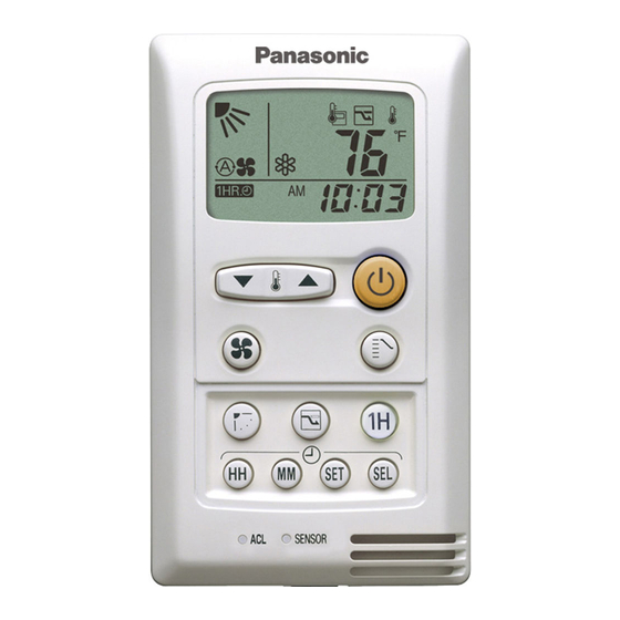
Page 16: Remote Controller
REMOTE CONTROLLER NOTE The descriptions on the AUTO ( ) or HEAT ( ) operation mode are only for the “COOL/DRY/HEAT Model,” and not for the “COOL/DRY Model.” Display Information on the operating conditions is displayed while the remote controller is switched on. If the unit is turned off, only the mode that was set previously is still displayed. - Page 17 ON/OFF operation button This button is for turning the air conditioner on and off. MODE selector button Use this button to select AUTO, HEAT, DRY, COOL or FAN mode. (AUTO) : When this setting is selected, the air conditioner calculates the difference between the thermostat setting and the room temperature and automatically switches to the ‘‘COOL’’...
- Page 18 REMOTE CONTROLLER (DISPLAY) Displayed when indoor unit sensor Displayed when operating NIGHT is in use SETBACK mode Displayed when setting temperature Displayed when temperature is shown Displayed when setting timer Symbols (1) Operation mode (3) Temperature setting 60 – 86 °F ......AUTO ........
-
Page 19: Operation With The Remote Controller
OPERATION WITH THE REMOTE CONTROLLER 1. Automatic Operation 2. Manual Operation (only for COOL/DRY/HEAT Model) • Single use This unit automatically switches between cooling operation and heating operation according to the difference between the room temperature and the temperature setting. •... -
Page 20: Adjusting The Fan Speed
3. Adjusting the Fan Speed A. In Cooling and DRY Mode: ( A. Automatic fan speed When the night setback mode is selected, the air conditioner Simply set the FAN SPEED selector button to the automatically raises the temperature setting 2 °F when 30 minutes have passed after the selection was made, and then another 2 °F position. -
Page 21: Setting The Timer
SETTING THE TIMER 3. How to set the ON time (Example) To start operation at 7:10 am. ON TIME Present time Operation Indication Press the SET button once. The timer indication alone flashes and the previous set- time is only displayed. •... -
Page 22: Using The 1-Hour Off Timer
USING THE 1-HOUR OFF ADJUSTING THE AIRFLOW TIMER DIRECTION The vertical airflow can be adjusted by moving the flap with the 1. 1-Hour OFF Timer remote controller. Do not move the flap with your hands. Confirm that the remote controller has been turned on. Use the FLAP button to set either the sweep function or one of the six airflow direction settings. - Page 24 APPENDIX B INSTALLATION INSTRUCTIONS (CZ-RD515U) CZ-RD515U (852-6-4190-592-00-0)
- Page 25 In order to install this wired remote controller onto a wall-mounted model, the connection kit IMPORTANT (CZ-RC515U or CZ-RC515UA), which must be purchased separately, is required. Once the wired remote controller is connected, the wireless remote controller cannot be used.
- Page 26 A. Installing with in-wall junction box In-wall junction box (locally purchased) (1) Install the junction box (locally purchased) into the wall. (Figs. 2-a and 3) (2) Pass the wire harness through the junction box and conduit. (Fig. 3) (3) Insert a flathead screwdriver into the 5 tab locations and disconnect the back plate of the remote controller by 2-3/8"...
- Page 27 How to wire the remote controller 5P FLAP 7P IND and 4P RC Ceiling wiring connector wiring connector panel (1) Turn OFF the power and remove the ceiling panel air-intake grille. (Refer to 3-6-1 Before Installing the Ceiling Panel in the Installation Instructions supplied with the indoor unit.) (2) Remove the 3 power box cover screws and 2 control box cover screws, then remove both covers.
- Page 28 How to Test Run the Air Conditioner After turning on the power of the air conditioner, use the remote controller and follow the steps below to conduct the test run. (1) Set the remote controller in Test Run mode. (Fig. 9) a)Press and hold the NIGHT SETBACK button and ON/OFF the 1HR.
- Page 30 APPENDIX C INSTALLATION INSTRUCTIONS Installing the Connection Kit for Wall-Mounted Models CZ-RC515U (852-6-4190-590-00-0)
- Page 31 INSTALLATION INSTRUCTIONS Connection Kit Parts included in the package See Table 1. Table 1 Parts Figure Q'ty Parts Figure Q'ty Parts Figure Q'ty Truss-head Phillips 5/32 13/32" Tapping Clamping (4 10mm) screw strap Wire (with a 7-3/32"(180mm) noise filter) Clamp Wire tube Top cover Installation...
- Page 32 (7) Feed the wire harness that was included in the wired remote controller package Component box into the right lower rear of the unit and route it to the component box. (Fig. 4a) When feeding the wire harness through the opening, be careful of the motor cable and be sure to feed the wire harness and motor cable together through the opening.
- Page 33 B. 18000 BTU and 24000 BTU inverter models (1) Remove the air intake grille. (2) Remove the terminal cover. Pull out the thermistor, then remove the grille. For details on steps (1) and (2), refer to the Installation Instructions included in the outdoor unit package.
- Page 34 How to Test Run the Air Conditioner After turning on the power of the air conditioner, use the remote controller and follow the steps below to conduct the test run. (1) Set the remote controller in Test Run mode. (Fig. 9) a) Press and hold the NIGHT SETBACK button and ON/OFF the 1HR.
- Page 36 APPENDIX D INSTALLATION INSTRUCTIONS Installing the Connection Kit for Wall Mounted Type 2 CZ-RC515UA (852-6-4190-591-00-0)
- Page 37 INSTALLATION INSTRUCTIONS Connection Kit Parts included in the package See Table 1. Table 1 Parts Figure Q'ty Parts Figure Q'ty Parts Figure Q'ty Truss-head Phillips 5/32 13/32" Tapping Clamping Noise filter (4 10mm) screw strap Installation Label Clamp instructions Installing the connection kit T ab (1) Remove the air intake grille.
- Page 38 Fig. 4 Fig. 5 Wire harness Screw To wired remote controller Clamping strap Fig. 6...
- Page 39 NOTE Wire harness Clamp Fig. 8 Fig. 7 label Fig. 9 Open hole Wire harness Fig. 10...
- Page 40 How to Test Run the Air Conditioner ON/OFF operation button NIGHT SETBACK button 1 HR.TIMER button ACL (Reset) SENSOR button button Fig. 11 Fig. 12 OPERATION lamp TIMER lamp NOTE Fig. 13 IMPORTANT WI1011-0 Printed in Japan...
- Page 42 DC1111-0...