
Related Manuals for Eaton MTL 9492-PS-PLUS


Summary of Contents for Eaton MTL 9492-PS-PLUS
- Page 1 Instruction manual January 2022 MTL intrinsic safety solutions INM MTL 9492-PS-PLUS Rev 3 MTL 9492-PS-PLUS Intrinsically safe power supply...
-
Page 2: Declaration Of Conformity
DECLARATION OF CONFORMITY A printed version of the Declaration of Conformity has been provided separately within the original shipment of goods. However, you can find a copy of the latest version at http://www.mtl-inst.com/certificates INM MTL 9492-PS-PLUS Rev 2... -
Page 3: Table Of Contents
8 ATEX, UKEX & IECEX CERTIFICATION INFORMATION . . . . . . . . . . . . . . . . . . . . . . . . . . . 17/18 INM MTL 9492-PS-PLUS Rev 2... -
Page 4: General Safety Information
No changes to any of the components that might impair their explosion protection are permitted. If any information provided here is not clear: Contact Eaton’s MTL product line or an authorised distributor or sales office. NOTE Improper installation and operation of the enclosure can result in the invalidation of the guarantee . -
Page 5: Features
MTL 94xx Series Ethernet modules mounted in a Zone 1 hazardous area. The MTL 9492-PS-PLUS may be mounted in a safe area, Zone 2 hazardous area. The output can be from either the Ex ia IIB or Ex ib IIB output connectors depending upon application. - Page 6 Each MTL 9492-PS-PLUS can power a single MTL 946x-ET Ethernet module. It is not permitted to connect to both ia and ib outputs on the same MTL 9492-PS-PLUS module . If multiple outputs are required for several Ethernet modules, there is a power distribution backplane available to simplify the 24VDC input connection to the modules, or alternatively a number of them can be DIN-rail mounted with a convenient “Powerbus”...
-
Page 7: Din-Rail Installation Method
DIN-RAIL INSTALLATION METHOD This section deals with mounting the individual MTL 9492-PS-PLUS power supplies on DIN rail, for backplane mounting see Section 4. WARNING ! If this module is to be connected to intrinsically safe apparatus, it must be installed, operated... -
Page 8: Mounting Power Supplies On Din Rail
Insert conductors according to the terminal assignments and tighten screws. If the wires are to be fitted with crimp ferrules, 10–12mm is the recommended length of the metal tube. If longer ones are used, they must be trimmed to 12mm before fitting. INM MTL 9492-PS-PLUS Rev 2... -
Page 9: Ambient Temperature Considerations
Use single ferrules with a crimp tool or insulation displacement connectors (Scotchloks). Suitable ferrules and connectors are provided with the kits. – + Optional insulation displacement connectors Figure 3 .3 Power bus wiring, joining and terminating INM MTL 9492-PS-PLUS Rev 2... -
Page 10: Earth Rail And Tagging Accessories
Spares replacement, for use with TAG57 tagging strip. MS010 DIN rail module spacer, 10mm, pack of 5 (figure 3 .8) Grey spacer; one required between each MTL 9492-PS-PLUS and any adjacent module on a DIN rail, to provide 10mm air-circulation space between modules. ETM7 Earth terminal, bag of 50 (figure 3 .9) - Page 11 35mm 10mm Figure 3 .8: MS010 DIN rail module spacers 10mm 14mm 14mm 10mm TYPE A TYPE B Type A Type B Figure 3 .10: Earth rails and clamps Figure 3 .9: ETM7 Earth terminals INM MTL 9492-PS-PLUS Rev 2...
-
Page 12: Assembly
Note: If necessary, provide additional support for long lengths of tagging strip by installing an extra IMB57 mounting block mid-way between the end mounting blocks. Snap out the perforated extension between the lugs on this mounting block. INM MTL 9492-PS-PLUS Rev 2... -
Page 13: Completed Assemblies
3 .5 .3 Completed assemblies Figure 3.12 illustrates a complete assembly of MTL 9492-PS-PLUS power supplies using the accessories mentioned above. The broken-line boxes either side of the assembly represent cable trunking, and the accompanying dimensions represent the minimum spacing between trunking and assemblies. -
Page 14: Backplane Mounting Variant
See the table for details of the kits and accessories applicable to the mounting methods and Figure 4.1 for dimensions and mounting centres. Note: Before mounting a MTL 9492-PS-PLUS on a backplane two minor modifications must be made. Remove the DIN-rail mounting clip by compressing the small spring inside the clip with a screwdriver and then removing it;... - Page 15 Plain washer (3) backplane Spacer (5) Mounting hole A Retaining washer (6) DIN-rail mounting foot G-section DIN rail (8) Figure 4 .4: Mounting a backplane onto DIN rail Figure 4 .7: Mounting a tagging-strip post INM MTL 9492-PS-PLUS Rev 2...
-
Page 16: Surface Mounting - With Kit Sms01
Attach the plastic retaining tie (7) with two plastic rivets (8) (Figure 4.7). Clip the tag strip holder (6) onto the mounting posts (1) by pushing it downwards (Figure 4.8). If required, swivel the tagging strip vertically (Figure 4.9) INM MTL 9492-PS-PLUS Rev 2... - Page 17 Figure 4 .9: Attaching an earth-rail post to PWR2 connector CPS08 Plastic Earth retaining rivets (7) terminals (6) Earth rail (5) CPS08 Figure 4 .12: “Ring” wiring multiple backplanes Figure 4 .10: Attaching earth rail terminals and rivets INM MTL 9492-PS-PLUS Rev 2...
-
Page 18: Backplanes - Earth Rails
Fitting MTL 9492-PS-PLUS modules to backplane WARNING ! When installing MTL 9492-PS-PLUS power supply modules it is essential to make sure that intrinsically safe and non-intrinsically safe wiring is segregated as required by a nationally accepted authority or as described in BS EN 60079-14, ISA RP 12.6 or DIN VDE-165. - Page 19 IIB LEDs Haz 1-3 output Serial ia IIB number output Latching mechanism Safe area power connector Figure 4 .14: Key elements of the MTL 9492-PS-PLUS power supply Figure 4 .16: Removing power supplies from backplane INM MTL 9492-PS-PLUS Rev 2...
-
Page 20: Environmental
(Ta = -40°C to +70°C) Ex nA IIB T4 Gc (Ta = -40°C to +70°C) Cert. no. CML 15ATEX4072X IECEx CML 15.0034X CML 21UKEX41070X * (for guidance on marking) Notes Terminals 1 and 3 Terminals 5 and 6 INM MTL 9492-PS-PLUS Rev 2... -
Page 21: Atex, Ukex & Iecex Certification Information
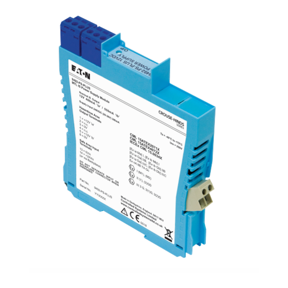
Access to the internal circuitry must not be made during operation. Repair This product cannot be repaired by the user and must be replaced with an equivalent certified product. continued on next page INM MTL 9492-PS-PLUS Rev 2... - Page 22 Each device is marked in accordance with the Directive/Statutory Requirements and CE and UKCA marked with the Notified/Approved Body Identification Number. This information applies to products manufactured during or after the year 2010. Figure 8 .1 MTL 9492-PS-PLUS product label INM MTL 9492-PS-PLUS Rev 2...
- Page 23 This page left intentionally blank INM MTL 9492-PS-PLUS Rev 2...
- Page 24 Tel: + 44 (0)1582 723633 Fax: + 44 (0)1582 422283 right to make design changes. THE AMERICAS: E-mail: mtlenquiry@eaton.com +1 800 835 7075 www.mtl-inst.com mtl-us-info@eaton.com © 2022 Eaton All Rights Reserved ASIA-PACIFIC: +65 6 645 9888 Publication No. INM MTL 9492-PS-PLUS Rev 3 040122 sales.mtlsing@eaton.com January 2022...