Table of Contents
Advertisement
Quick Links
Advertisement
Table of Contents
Troubleshooting

Related Manuals for Motorola GX2 EA1000C Series


Summary of Contents for Motorola GX2 EA1000C Series
- Page 1 User Guide GX2 EA1000C*/* Multi-Wavelength DWDM 1550 nm Laser Transmitter...
- Page 2 Motorola, Inc. Motorola reserves the right to revise this publication and to make changes in content from time to time without obligation on the part of Motorola to provide notification of such revision or change. Motorola provides this guide without warranty of any kind, implied or expressed, including, but not limited to, the implied warranties of merchantability and fitness for a particular purpose.
-
Page 3: Compliance/Regulatory
Compliance/Regulatory Compliance/Regulatory Caution These servicing instructions are for use by qualified personnel only. To reduce the risk of electrical shock, do not perform any servicing other than that contained in the Installation and Troubleshooting Instructions unless you are qualified to do so. Refer all servicing to qualified service personnel. Special Symbols That Might Appear on the Equipment This is a class I product that contains a class IIIb laser and is intended for operation in a closed DANGER... - Page 4 Compliance/Regulatory Caring for the Environment by Recycling When you see this symbol on a Motorola product, do not dispose of the product with residential or commercial waste. Recycling your Motorola Equipment Please do not dispose of this product with your residential or commercial waste. Some countries or regions, such as the European Union, have set up systems to collect and recycle electrical and electronic waste items.
- Page 5 This product meets the requirements of the Code of Federal Regulations, Title 21, Chapter I, Subchapter J, Sections 1010.2, 1010.3, 1040.10, and 1040.11 CLASS 1 LASER PRODUCT Declaration of Conformity Motorola Mobility, Inc. 101 Tournament Drive Horsham, PA 19044, U.S.A. declare under our sole responsibility that the...
-
Page 6: Table Of Contents
Contents Contents Compliance/Regulatory ......................... i Tables ............................. vi Figures ............................vi Introduction ............................ 1 Related Documentation ........................3 Getting Help ............................. 4 Customer Service (order entry) ....................5 Replacement Parts ........................5 Repair ............................5 Overview ............................6 Module Description ......................... 7 Operating Modes ........................... - Page 7 Contents Embedded Section ........................30 Boot Operation ..........................30 Operating Modes ........................... 30 AGC Modes ..........................31 MGC Modes ..........................32 Additional Controls and Configurations ..................33 Optical Output Control ......................33 RF Drive Level Control ......................33 Quick Swap ..........................33 Implementing a Reduced Channel Load ..................
- Page 8 Tables Tables Table 1: Minimum GX2-HSG* Equipment-Shelf Configuration ............7 Table 2: GX2-EA1000CC*/* Front Panel Features ................ 14 Table 3: GX2-EA1000C*/* Rear Panel Features ................16 Table 4: GX2-EA1000C*/* Alarm Conditions ................. 38 Table 5: Troubleshooting using the status LED only ..............43 Table 6: Troubleshooting —...
-
Page 9: Introduction
Introduction Introduction ® The OmniStar GX2 is a fiber optic broadband transmission platform for headend and hub locations that supports advanced broadband hybrid-fiber/coax telecommunications systems. The OmniStar GX2 platform includes a complete line of headend fiber optic products designed to transport video and data signals in CATV systems and related applications. -
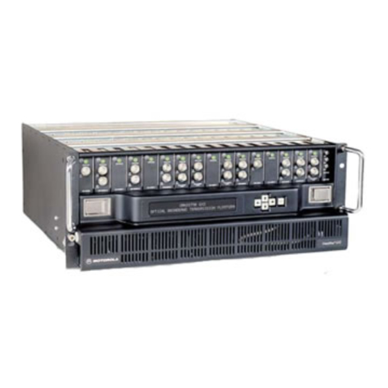
Page 10: Figure 2: Fully Populated Gx2-Hsg* Equipment Shelf
Figure 2: Fully populated GX2-HSG* equipment shelf For more information regarding this product or other OmniStar GX2 modules, consult the Motorola product catalog or visit the web site: http://www.motorola.com/broadband. GX2 EA1000C*/* Multi-Wavelength DWDM 1550 nm Laser Transmitter • User Guide... -
Page 11: Related Documentation
Introduction Related Documentation The following documents provide information that is required for products that can be used with the GX2-EA1000C*/*: • GX2-HSG* Equipment Shelf Installation and Operation Manual • GX2-CM100B Control Module Installation and Operation Manual • GX2-PSAC10*-R AC Power Supply Installation and Operation Manual •... -
Page 12: Getting Help
Introduction Getting Help To get assistance with your Motorola product or solution, or to access learning materials, use one of the following channels: Technical Assistance Center (TAC) provides access to technicians 24 hours a day, 7 days a week for all products. Contact the TAC at 888-944-HELP (888-944-4357) or dial direct 847-725-4011. -
Page 13: Customer Service (Order Entry)
Terminal Products: 800-227-0450 Repair If repair is necessary, call the Motorola Technical Support Call Center for assistance in verifying that the item is defective. The TSCC will create an RSA for repair or an RA for replacement if equipment qualifies. -
Page 14: Overview
Overview Overview OmniStar GX2 equipment is designed for increased rack density, reliability, ease of operation, and computer-aided troubleshooting through extensive network management. All OmniStar GX2 modules are accessible and replaceable from the front of the GX2-HSG* equipment shelf, resulting in low time-to-repair. An installed module mates with the equipment shelf connectors for signal interfacing and power. -
Page 15: Module Description
Overview Table 1: Minimum GX2-HSG* Equipment-Shelf Configuration Co mp on en t Mo de l Fu nc ti o n GX2-HSG* Rack-mountable shelf that houses up to sixteen modules, AC or Equipment-shelf DC power supplies, and a control module GX2-PSAC10* or The GX2-PSAC10*provides shelf power in an AC powered Power supply GX2-PSDC10*... -
Page 16: Figure 4: Gx2-Ea1000C*/* Block Diagram
Overview Figure 4: GX2-EA1000C*/* Block Diagram A single front-panel mounted RF test point is provided for setup and maintenance of the module. The test point directly monitors the combined RF input. The rear panel contains two RF inputs and two cooling fans. Complete descriptions of the front and rear panel features are provided later in this section. -
Page 17: Figure 5: Gx2-Ea1000C*/* Front And Rear Side Views
Overview Figure 5: GX2-EA1000C*/* Front and Rear Side Views GX2 EA1000C*/* Multi-Wavelength DWDM 1550 nm Laser Transmitter • User Guide 589569-001-a... -
Page 18: Operating Modes
Overview Operating Modes The user can select one of several operating modes depending on the application. The modes are characterized as either Automatic Gain Control (AGC) or Manual Gain Control (MGC): AGC Modes Each of the following modes uses the AGC function of the module. The specific mode determines the laser drive level relative to the factory-set reference point: •... -
Page 19: Additional Features
Overview Additional Features Functions performed by the GX2-EA1000C*/* include: • Provides local alarm indication by changing the color of the front-panel STATUS • Stores module identity, laser operating parameters, and set-up information in NVM • Downloadable firmware to support field upgrades •... -
Page 20: Embedded Section
Overview Embedded Section The microprocessor section controls and monitors the laser module. The main and local microprocessors: • Control the RF level into the laser, the laser temperature, and its optical-output power. • Monitor laser module status and alarm conditions. •... -
Page 21: Front-Panel
Overview Front-Panel The GX2-EA1000C*/* front panel includes an optical connector, a tri-color alarm STATUS indicator, and one RF test point. Figure 6: GX2-EA1000C*/*front panel GX2 EA1000C*/* Multi-Wavelength DWDM 1550 nm Laser Transmitter • User Guide 589569-001-a... -
Page 22: Table 2: Gx2-Ea1000Cc*/* Front Panel Features
Overview Table 2: GX2-EA1000CC*/* Front Panel Features K ey Fe a tu re Fu nc ti o n There are three status LED colors: Green indicates normal operation with no alarms reported. Yellow indicates a minor alarm is detected. A minor alarm signals an out-of-tolerance monitored parameter value, but the system can operate. -
Page 23: Rear Panel
Overview Rear Panel The GX2-EA1000C*/* rear panel includes cooling fans, the main (broadcast) RF input, secondary (narrowcast) RF input, and power/signal connector. Figure 7: GX2-EA1000C*/* Rear Panel GX2 EA1000C*/* Multi-Wavelength DWDM 1550 nm Laser Transmitter • User Guide 589569-001-a... -
Page 24: Table 3: Gx2-Ea1000C*/* Rear Panel Features
Overview Table 3: GX2-EA1000C*/* Rear Panel Features K ey Fe a tu re Fun c ti o n Forced air fan that is required to circulate cooling air. Additional forced air fan that is required to circulate cooling air. G-type connector for main (broadcast) RF input to the GX2-EA1000C*/*. This connector mates with the G- to F-type adapter on the GX2-HSG*. -
Page 25: Installation And Setup
Installation and Setup Installation and Setup This section provides instructions on how to install the GX2-EA1000C*/*, connect it to other equipment, select the operating mode, and verify its operation. To function, the GX2-EA1000C*/* requires a GX2-HSG* equipment shelf configured with a GX2-PSAC10D-R or GX2-PSDC10D-R power supply and a GX2-CM100B control module. -
Page 26: Unpacking The Gx2-Ea1000C
Unpacking the GX2-EA1000C*/* 1. Unpack the GX2-EA1000C*/* and inspect it for damage. If damaged, set it aside in its original packing material and contact the Motorola Customer Service department for further instructions. See Section 1, “Introduction.” 2. Record the model number, serial number, and related information for future reference. -
Page 27: Cleaning The Gx2-Ea1000C*/* Optical Bulkhead Fitting
Installation and Setup The GX2-HSG* is now ready to accept the GX2-EA1000C*/*. However, before you insert the GX2-EA1000C*/* into the GX2-HSG*, you need to perform some basic cleaning procedures on the optical interfaces. It is highly recommended that the following cleaning procedures be performed prior to installing the GX2-EA1000C*/* in the GX2-HSG*. -
Page 28: Cleaning The Interface Fiber Jumper Sc/Apc Connector
Installation and Setup Figure 9: Cleaning the Barrel of the Optical Bulkhead Fitting Cleaning the Interface Fiber Jumper SC/APC Connector In addition to cleaning the optical bulkhead on the GX2-EA1000C*/*, it is also important to clean the interface fiber jumper optical connector(s). This cleaning should be performed before you insert the GX2-EA1000C*/* into the GX2-HSG*. -
Page 29: Inserting The Sc/Apc Connector
Installation and Setup Inserting the SC/APC Connector Before inserting the GX2-EA1000C*/* into the GX2-HSG*, insert the interface fiber jumper SC/APC connector into the optical bulkhead fitting. It is recommended that you use a short optical jumper for initial GX2-EA1000C*/* installation. This provides greater flexibility for installation and can be used to verify the optical output power after the unit is installed. -
Page 30: Installing The Gx2-Ea1000C*/* In The Gx2-Hsg
Installation and Setup DANGER! Subsequent to the initial installation, when any of the above optical cleaning procedures are performed, it is recommended that power be removed from the GX2-EA1000C*/* transmitter for your protection. Installing the GX2-EA1000C*/* in the GX2-HSG* You are now ready to insert the GX2-EA1000C*/* into the GX2-HSG*. All slots in the GX2-HSG* are universal and intended for the Omnistar GX2 application modules, except the narrow, right-most slot, which is reserved for the control module. -
Page 31: Figure 13: Gx2-Ea1000C*/* Installation In A Gx2-Hsg
Installation and Setup Figure 13: GX2-EA1000C*/* installation in a GX2-HSG* GX2 EA1000C*/* Multi-Wavelength DWDM 1550 nm Laser Transmitter • User Guide 589569-001-a... -
Page 32: Power-Up And Reset Initialization
Installation and Setup Figure 14: Inserting the GX2-EA1000C*/* in the GX2-HSG* Power-Up and Reset Initialization When the GX2-EA1000C*/* is fully installed in the GX2-HSG* and power is applied, the initialization process begins. The GX2-EA1000C*/* LED completes a red–yellow– STATUS green cycle. Upon initial power-up of a new unit, the GX2-EA1000C*/* conforms to the factory default Preset/Video mode with a 4 dB video mode offset from CW. -
Page 33: Measuring And Checking The Optical Output Power
Installation and Setup Measuring and Checking the Optical Output Power The following procedures for measuring optical output power and routine maintenance of the GX2-EA1000C*/* should be performed by properly trained personnel. In all cases they should be aware of and observe the following warnings associated with fiber optic transmitters: D A N G E R ! Laser Hazard! Invisible laser radiation when the module is operating and the interlock defeated. -
Page 34: Measuring And Checking The Rf Input Signal Levels
Installation and Setup Measuring and Checking the RF Input Signal Levels Following verification of the optical output power, you need to confirm the levels of the RF input signal being applied to the GX2-EA1000C*/*. To measure and check the RF input signal levels: 1. -
Page 35: Protecting The Laser
Installation and Setup Figure 15: GX2-HSG*rear-panel RF connections Upon receipt of an acceptable RF input signal level, the GX2-EA1000C*/* front panel LED illuminates green. STATUS With RF input signals applied to the GX2-EA1000C*/*, you can monitor the broadcast RF input level using on the front panel without removing the RF signal from the rear RF TP of the GX2-HSG*... -
Page 36: Operating Modes
Installation and Setup Operating Modes Select the preferred GX2-EA1000C*/* operating mode, MGC or AGC. Reminder—on initial power up, the factory default is Preset/Video mode with a 4 dB Video mode offset from CW. The following subsections describe how to set up the GX2-EA1000C*/* based on the operating mode selected. -
Page 37: Agc Modes
Installation and Setup AGC Modes To implement AGC modes: 1. Adjust the input signal levels per the GX2-EA1000C*/* specification, as described previously in “Measuring and Checking the RF Input Signal Levels.” 2. If the BC and NC signals are both applied to the main input, the total CW input signal power should be approximately −14 dBm or +34.75 dBmV. -
Page 38: Operation
Operation Operation This section describes the GX2-EA1000C*/* embedded section, user selectable operating modes, and network management system, and provides information necessary to properly use the optional SDU. It also provides information on increasing and decreasing channel loading and, if necessary, how to download new GX2- EA1000C*/* firmware. -
Page 39: Agc Modes
Operation AGC Modes The following settings (submodes) are available in AGC: Preset Preset is a primary mode that establishes the factory default setting and maintains an ideal RF input level to the laser. The laser RF input level is maintained by (1) sampling the main RF-path power through an internal RF power meter, (2) comparing it to a factory-calibrated default AGC power level stored in NVM, and (3) adjusting the RF attenuator until the factory calibrated default AGC power level is achieved. -
Page 40: Mgc Modes
Operation CW/Video CW is a secondary mode that uses unmodulated channels for a proof-of-performance rating. Video is also a secondary mode that is used when modulated channels are applied to the input of the GX2-EA1000C*/*. CW and Video are used in conjunction with Preset and Set. -
Page 41: Additional Controls And Configurations
Operation Additional Controls and Configurations The following subsections describe additional features of the GX2-EA1000C*/*. Optical Output Control You can turn the optical output power from the laser diode ON and OFF using the local interface port, the network management system, or the optional SDU. The factory default setting is ON. -
Page 42: Implementing A Reduced Channel Load
Operation The GX2-EA1000C*/* reads the quick-swap message from the GX2-CM100B, automatically resets, and re-initializes itself to the same configuration as contained in the message. • If the GX2-EA1000C*/* is in Preset mode, it uses the factory default optimum OMI setting to determine the RF level at the laser. •... -
Page 43: Implementing An Increased Channel Load
Operation Implementing an Increased Channel Load Many systems operate under a reduced channel load with the capacity to add additional channels as required. If the system initially operated with less than a full load (79 NTSC channels from 52 through 550 MHz and 450 MHz of digital at –6 dBc from 550 through 1002 MHz) and you need to increase the channel load, you may have to decrease the RF input level per channel accordingly in order to maintain an optimum drive level to the laser. -
Page 44: Using Set Mode
Operation Using Set Mode To implement an increased channel load using Set mode: 1. Operate the GX2-EA1000C*/* in Preset mode and apply the preferred initial channel load. 2. Allocate time for the AGC to adjust the RF drive level to the laser. 3. -
Page 45: Using Preset Mode (With Agc Control In The Gx2-Ea1000C*/* Only)
Operation 4. Allocate time for the AGC to adjust the RF drive level to the laser and to adjust the levels at the nodes. 5. Apply the additional channel load. 6. Allocate time for the AGC to adjust levels to the new channel load. 7. -
Page 46: Table 4: Gx2-Ea1000C*/* Alarm Conditions
Operation Table 4: GX2-EA1000C*/* Alarm Conditions Status Alarm Description RF Input Loss-of-Signal: Minor Low Alarm Yellow Optical Output Power: Major High Alarm Major Low Alarm TEC Temperature Deviation: Major High Alarm Minor High Alarm Yellow Minor Low Alarm Yellow Major Low Alarm Laser Bias Current: Major High Alarm Major Low Alarm... - Page 47 Operation Status Alarm Description Major Low Alarm Fan Speed (report for each fan): Minor Low Alarm Yellow Major Low Alarm S ta tus Al ar m D es c ri pt io n Li m it LE D Ac t io n NVM CRC Error: Factory Data Minor Alarm Fail...
-
Page 48: Operating The Gx2-Ea1000C*/* With The Optional Sdu
Operation Operating the GX2-EA1000C*/* with the Optional SDU You can control and operate the GX2-EA1000C*/* using the optional SDU with display. This includes selecting any of the previously referenced control modes and the ability to monitor the numerous parameters and alarm conditions within the GX2-EA1000C*/*. Appendix B, “Menus”... -
Page 49: Full Spectrum Multi-Wavelength Application
With this recommendation, it would make sense for pay-as-you grow systems to start with Ch 29 or Ch 31 as a single wavelength and grow from there. Understanding the impacts of FWM, Motorola has incorporated functionality into the GX2-EA1000C*/* product line to reduce these issues by offsetting select channels within the ITU channel bandwidth. -
Page 50: Troubleshooting
Troubleshooting Troubleshooting This section provides troubleshooting procedures for the GX2-EA1000C*/*. You can use the procedures to correct minor problems or better define the malfunction. If the error condition cannot be corrected, contact the TRC at 1-888-944-HELP (1-888-944-4357). Before you call, record the input signal levels, optical output power, operating mode(s), and ambient temperature. -
Page 51: Table 5: Troubleshooting Using The Status Led Only
Troubleshooting Table 5: Troubleshooting using the status LED only S y mp to m S ta tus LED I ndic a tio n P o o r R F F l a s h i n g R e d Y e l l o w N o t L i t R e s p o n s e... -
Page 52: Using Available Options
Troubleshooting S y mp to m S ta tus LED I ndic a tio n P o o r R F F l a s h i n g R e d Y e l l o w N o t L i t R e s p o n s e Co r rec t iv e Ac tio n R e d... -
Page 53: Table 6: Troubleshooting - Using Available Options
Troubleshooting Table 6: Troubleshooting — Using Available Options S ta tus R ep o r te d Al ar m Con di ti on Va lu e Co r rec t iv e Ac tio n RF Input Loss-of-Signal: Minor Low Alarm Yellow Optical Output Power: Major High Alarm... - Page 54 Troubleshooting S ta tus R ep o r te d Al ar m Con di ti on Va lu e Co r rec t iv e Ac tio n TEC Current: Major Low Alarm Module Temperature: Major High Alarm Module Temperature: Minor High Alarm Yellow Module Temperature:...
-
Page 55: Specifications
Specifications Specifications Specifications for the GX2-EA1000C*/* are valid over the given bandwidth and operating temperature range listed in this section. The current Motorola Product Catalog may contain additional information not listed below. RF bandwidth 52 through 1003 MHz RF input impedance... -
Page 56: Physical
Specifications Storage temperature range −40°C to +80°C (−40°F to +176°F) Software and hardware active Over temperature laser protection Physical Dimensions 1”W × 5.9”H × 14.6”D (2.5 cm × 15 cm × 37.1 cm) Weight 2.0 lbs. (1 kgs) GX2 EA1000C*/* Multi-Wavelength DWDM 1550 nm Laser Transmitter • User Guide 589569-001-a... -
Page 57: Gx2-Ea1000C*/* Models
Specifications GX2-EA1000C*/* Models Figure 16 identifies the conventions for the model numbers of the GX2-EA1000C*/*. Figure 16: GX2-EA1000C*/* Model Number Conventions GX2 EA1000C*/* Multi-Wavelength DWDM 1550 nm Laser Transmitter • User Guide 589569-001-a... -
Page 58: Menus
Menus Menus This appendix provides information about: • Using the GX2-EA1000C*/* menus • The menu structure • Using the optional SDU with display Table 7: Using the GX2-EA1000C*/* Menus Ac t ion How To Scroll through the Press the up or down arrows to scroll through RF/OPTICAL, MODULE top-level menu STATUS, MODULE INFO, and REMOTE. -
Page 59: Rf/Optical Menu
Menus RF/OPTICAL Menu MODE PRESET|SET|SET EQUATE|MANUAL| MANUAL EQUATE SIGNAL TYPE CW|VIDEO CW / VIDEO OFFSET 1dB|2dB|3dB|4dB|5dB OPTICAL OUTPUT ON|OFF RF INPUT ON|OFF ATTENUATOR SETTING xx.y dB Can only be changed in manual mode. OMI OFFSET CONTROL xx.yy dB Can only be changed in set mode. OMI OFFSET MONITOR xx.yy dB OPTICAL POWER... -
Page 60: Module Info Menu
Menus MODULE INFO Menu ALIAS THIS-ALIAS (OMNISTAR GX2-EA1000C LASER MODULE) MODEL GX2-EA1000C* SERIAL NUMBER 0123456789ABCDEF DATE CODE mm/dd/yyyy FIRMWARE REVISION HARDWARE REVISION GX2 EA1000C*/* Multi-Wavelength DWDM 1550 nm Laser Transmitter • User Guide 589569-001-a... -
Page 61: Status Reporting
Status Reporting Status Reporting This appendix provides information on status reporting messages for the Element Management System and shelf display. The event and display messages on the GX2- EA1000C* are listed in Table 9. Table 8: Event/Alarm messages for the GX2-EA1000C*/* Transmitter SD U Dis p la y S ta tus... - Page 62 Status Reporting SD U Dis p la y S ta tus EM S E ve nt Mes s ag e M es s a ge E v en t Major High Alarm Laser Bias Current: Major Low Alarm TEC Current: Major High Alarm TEC Current: Major Low Alarm...
- Page 63 Status Reporting SD U Dis p la y S ta tus EM S E ve nt Mes s ag e M es s a ge E v en t Fan 2 Speed: Major Low Alarm GX2 EA1000C*/* Multi-Wavelength DWDM 1550 nm Laser Transmitter • User Guide 589569-001-a...
- Page 64 MOTOROLA and the Stylized M logo are trademarks or registered trademarks of Motorola Trademark Holdings, LLC. All other product or service names are the property of their registered owners. ©2012 Motorola Mobility, Inc. All rights reserved. 589569-001- a 06/12...