Table of Contents
Advertisement
Quick Links
TABLE OF CONTENTS
1 Safety Precautions----------------------------------------------- 2
2 Specifications ----------------------------------------------------- 3
3 Technical Descriptions ----------------------------------------- 4
4 Location of Controls and Components ------------------- 7
5 Operating Instructions------------------------------------------ 8
6 Troubleshooting Guide ----------------------------------------16
7 Disassembly and Assembly Instructions ---------------33
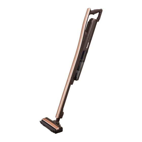
Rechargeable Vacuum Cleaner
Model No.
Model No.
Model No.
Model No.
Model No.
Model No.
Model No.
Model No.
Product Color -S: Silver black
Destination
PAGE
8 Wiring Connection Diagram--------------------------------- 50
9 Exploded View and Replacement Parts List ----------- 53
© Panasonic Corporation 2017 Unauthorized copy-
ing and distribution is a violation of law.
Order Number VCB1705001CE
MC-BJ870-S149
MC-BJ870-S447
MC-BJ870-T447
MC-BJ870-SB49
MC-BJ870-TB49
MC-BJ870-SV47
MC-BJ870-TV47
MC-BJ870-SZ47
-T: Bronze brown
Iran: 149
Hong Kong: 447
Thailand: B49
Malaysia: V47
Saudi Arabia: Z47
PAGE
Advertisement
Table of Contents

Related Manuals for Panasonic MC-BJ870-S149


Summary of Contents for Panasonic MC-BJ870-S149
-
Page 1: Table Of Contents
3 Technical Descriptions ----------------------------------------- 4 4 Location of Controls and Components ------------------- 7 5 Operating Instructions------------------------------------------ 8 6 Troubleshooting Guide ----------------------------------------16 7 Disassembly and Assembly Instructions ---------------33 © Panasonic Corporation 2017 Unauthorized copy- ing and distribution is a violation of law. -
Page 2: Safety Precautions
1 Safety Precautions To prevent causing accidents during maintenance and ensure product safety after maintenance, the items that must be abided by will be described below:... -
Page 3: Specifications
2 Specifications... -
Page 4: Technical Descriptions
3 Technical Descriptions 3.1. Lithium-ion battery ■To make the battery last longer • If the vacuum cleaner is not being used for more than a month, fully charge the battery before storing the vacuum cleaner and recharge the battery once a year. (If the vacuum cleaner is stored with an uncharged battery, it may cause the battery to become defective or reduce the battery life.) •... - Page 5 ■Charging adapter and “standby,” “charging,” and “cleaning” modes • Cleaning mode: when the vacuum cleaner is in use • Charging mode: when the battery is being recharged • Standby mode: when the vacuum cleaner is switched off <Charging adapter and relation to “standby,” “charging,” and “cleaning” modes> 1.
- Page 6 3.2. Anti-idling function 3.3. Dust sensor function ■Activating and deactivating the anti-idling function ■Changing the dust sensor sensitivity setting...
-
Page 7: Location Of Controls And Components
4 Location of Controls and Components 4.1. MC-BJ870... -
Page 8: Operating Instructions
5 Operating Instructions 5.1. Preparation (Excerpts from the instruction manual) - Page 9 5.2. Charging (Excerpts from the instruction manual)
- Page 10 5.3. How to use the Vacuum Cleaner (Excerpts from the instruction manual)
- Page 12 5.4. Maintenance / Changing The Settings (Excerpts from the instruction manual)
- Page 15 5.5. Product Disposal / Trouble Shooting (Excerpts from the instruction manual)
-
Page 16: Troubleshooting Guide
6 Troubleshooting Guide 6.1. Information lamps (LEDs) (MC-BJ870) Information conveyed by various lamps (LEDs) *The information conveyed varies according to whether lamps (LEDs) are lit up or blinking, and the blinking speed. - Page 17 6.2. Troubleshooting quick reference table (MC-BJ870) *When performing inspection or repairs, carry out the inspection or actions for the various symptoms based on this quick reference table. *The circled numbers in the table indicate components that may be faulty, causing the symptom.
- Page 18 6.2.1. Confirming order for the symptoms and parts to be checked Confirmation code A: The vacuum cleaner does not work even when the “AUTO/HIGH” switch is pressed. (The battery status indicator lamp does not light up and the motor fan unit and Nozzle motor unit do not work.) Confirmation code B: The vacuum cleaner does not work even when the “AUTO/HIGH”...
- Page 19 Confirmation code K: The “DUST SENSOR” lamp does not light up. Confirmation code L: The “DUST SENSOR” lamp remains lit up and does not go out. Symptom No. Check point Reference P.C.B D unit 6.3.3.5.Checking the dust sensor (P.C.B D unit) Lead wire A assy 6.3.3.6.Checking Lead wire A assy P.C.B K unit...
- Page 20 6.2.2. Inspection flow for each symptom...
- Page 23 6.3. Inspected component/what to check/action based on the troubleshoot- ing quick reference table 6.3.1. Diagnosis for charging components 6.3.1.1. Checking the charging adapter ■What to check/Method <Check 1> Checking the charging adapter for deformity or damage • Check whether there is any heat deformation, etc. in the main unit of the charging adapter. •...
- Page 24 ■Action • Replacing the Lithium-ion battery 6.3.3. Diagnosis for main unit components 6.3.3.1. Checking the Motor assy ■What to check/Method <Check 1> Checking for damage or burnout of lead wires and connectors. • Check whether there is any damage, burnout or poor connection of connectors and lead wires. <Check 2>...
- Page 25 6.3.3.2. Checking the P.C.B A unit ■What to check/Method <Check 1> Checking the insertion, connection and conduction conditions of the connector housing • Make a visual check of whether the lead wires A unit and relay connectors are properly inserted and connected. •...
- Page 26 6.3.3.3. Checking the P.C.B B unit ■What to check/Method <Check 1> Checking the insertion, connection and conduction conditions of the connector housing • Make a visual check of whether the connector housing from the P.C.B A unit is properly inserted and connected. •...
- Page 27 6.3.3.4. Checking the P.C.B K unit ■What to check/Method <Check 1> Checking the insertion, connection and conduction conditions of the connector housing • Make a visual check of whether the connector housing from the P.C.B A unit is properly inserted and connected. •...
- Page 28 6.3.3.5. Checking the dust sensor (P.C.B D unit) ■What to check/Method <Check 1> Checking the Front body assy dust sensor • Check that there lint, hair, dust or foreign objects clinging to the sensor. <Check 2> Checking the insertion, connection and conduction conditions of the connector housing •...
- Page 29 6.3.3.7. Checking the dust box ■What to check/Method <Check 1> Checking how the dust box is set in the main unit • If the dust box is not properly set, the vacuum cleaner will not be able to suck up dust. <Check 2>...
- Page 30 6.3.4. Diagnosis for Power nozzle/Extension wand 6.3.4.1. Checking the Nozzle motor unit ■What to check/Method <Check 1> Checking the voltage between the Power nozzle connection terminals of the main unit • Measure the voltage between the terminals on the underside of the main unit and if it exceeds DC 18.0 V, inspect the Power noz- zle.
- Page 31 6.3.4.2. Checking the P.C.B E unit ■What to check/Method <Check 1> Check • Measure the voltage between the terminals on the underside of the main unit and if it exceeds DC 18.0 V, inspect the Power noz- zle. <Check 2> Conduction check of micro-switch •...
- Page 32 6.3.4.4. Checking the belt ■What to check/Method <Check 1> Visual check of the belt for any deformity, damaged (breakage) or wear ■Action • Replacing the belt 6.3.4.5. Checking the Extension wand ■What to check/Method <Check 1> Conduction check of Extension wand •...
-
Page 33: Disassembly And Assembly Instructions
7 Disassembly and Assembly Instructions Precautions 1. When disassembling parts, first check the state of the assembled parts and the wiring (layout) and be sure to return them to their proper state after completion of repairs. 2. Handle disassembled parts and packing, etc. with care, and if anything becomes damaged replace it with a new part. 3. - Page 34 7.1. Disassembly of the main unit *Before commencing disassembly work, verify that the Lithium-ion battery has been removed from the main unit. 7.1.1. Preparation • Lift up the end with the hook, detach it from the connec- tor and remove the Lithium-ion battery. 1.
- Page 35 7.1.2. Power indicator window unit 3. Using a flathead screwdriver on the hooks on either side of the Painted handle cover on the front of the Front body *The main unit can be disassembled by removing the assy, release the hooks from the body A unit hook. In the Power indicator window unit and Painted handle cover.
- Page 36 7.1.4. P.C.B K unit <Precautions when carrying out assembly> • Before attaching the Painted handle cover to the main unit, 1. Remove the connectors and take out the P.C.B K unit. first check that the Seal packing C is fitted into place accord- ing to the diagram.
- Page 37 7.1.5. Lead wire A assy, dust sensor 4. Remove the connectors from the P.C.B D unit. 1. Remove the lead wire relay connectors. ■Caution • When rmoving connectors, pull them straight out. If they are pried out, it may cause a break or poor contact of the lead wire.
- Page 38 5. Disconnect the Lead wire A assy and disconnect the con- 2. Disconnect the arrow hooks indicated in the diagram and nection terminals. remove the Lower handle from the body A unit. <Precautions when carrying out assembly> 7.1.6. Lower handle •...
- Page 39 7.1.8. P.C.B B unit 2. Insert a flathead screwdriver or similar tool into the arrow hooks indicated in the diagram and, using the screwdriver 1. Take out the P.C.B B unit from the body A unit and as a lever to pull the Handle grip unit to the outside, remove the connectors.
- Page 40 7.1.10. P.C.B A unit 3. Remove the Front body assy securing screws by the bat- tery storage compartment (2 screws). 1. Pull out the lead wires from the storage compartment on the upper part of the body A unit. 4. Slightly raise the Front body assy and, using a flathead 2.
- Page 41 ■Caution 4. Disconnect the connectors and faston terminals from the • Do not force the P.C.B holder A unit when removing it P.C.B A unit (2 points). from the body A unit. There is a risk that lead wires, con- nectors, etc.
- Page 42 7.1.11. Motor assy • Arrange the charging jack and other lead wires in their original positions. 1. Disconnect the Motor assy lead wires from the body A unit. <Precautions when carrying out assembly> • When replacing the P.C.B holder A unit, affix the Body parti- tion packing.
- Page 43 3. Using a flathead screwdriver or similar tool to widen the 5. Remove the Motor support rubber front and Motor sup- body A unit, release the hooks and take out the Suction port rubber rear from the Motor assy. inlet unit. 4.
- Page 44 7.2. Disassembly of the Power nozzle ■The Power nozzle is specialized for MC-BJ870 (direct current). Do not replace it with a component from another model. 7.2.1. Brush cover 7.2.2. Agitator assembly 1. Lift up the Agitator assembly and remove the belt, then 1.
- Page 45 7.2.4. Lever unit ■Special screw The screws used to attach the Floor nozzle lower unit 1. Remove the Lever unit in the direction of the arrow. include one special screw as shown in the diagram below. Use a Torx screwdriver to remove the special screw. 7.2.5.
- Page 46 7.2.6. Floor nozzle pad left 7.2.8. Bumpers (left/right) 1. Insert a flathead screwdriver into the place indicated with 1. Remove the Bumpers (left and right). the arrows on the diagram and remove the Floor nozzle pad left from the Floor nozzle lower unit. 7.2.9.
- Page 47 3. Remove the securing screw (1 screw) and remove the Floor nozzle center. 7.2.10. Floor nozzle pipe unit 1. Remove the temperature sensor (Nozzle motor unit). ■Caution • When removing connectors, pull them straight out. If they are pried out, it may cause a break or poor contact of the lead wire.
- Page 48 4. While holding down the slider and slider spring, slowly • Be sure to securely fit the Switch spring into the groove remove the Floor nozzle pipe unit. in the Floor nozzle lower unit. • After checking that the steel ball is set in its proper place, attach the Switch cover.
- Page 49 7.2.12. Power nozzle assembly diagram...
-
Page 50: Wiring Connection Diagram
8 Wiring Connection Diagram 8.1. Actual wiring diagram (MC-BJ870) - Page 51 8.2. Wiring diagram (MC-BJ870 Main unit)
- Page 52 8.3. Wiring diagram (MC-BJ870 Floor nozzle part)
-
Page 53: Exploded View And Replacement Parts List
9 Exploded View and Replacement Parts List 9.1. MC-BJ870-S149 (Iran) 9.1.1. Exploded View (Main unit) - Page 54 9.1.2. Parts List (Main unit) MC-BJ870-S149 (Iran) Safety Ref.No Service Parts No. Part Name & Description Q'TY Remarks AMV05B-LH0S PAINTED HANDLE COVER (S)Silver Black AMV0CE-LH0 SEAL PACKING C XTN3+10BFJK PAN HEAD TAPPING SCREWS AMC0NA-ZK0 GLASS TAPE AMV0BG-LH0 LEAD WIRE A ASSY...
- Page 55 9.1.3. Exploded View (Accessories: Cleaner head nozzle, Power / Extension wand)
- Page 56 9.1.4. Parts List (Accessories: Cleaner head nozzle, Power / Extension wand) MC-BJ870-S149 (Iran) Safety Ref.No Service Parts No. Part Name & Description Q'TY Remarks AMV85P-NT0S CLEANER HEAD NOZZLE, POWER (POWER NOZZLE ASSY): (S)Silver Black AMV92QNT0S0J FLOOR NOZZLE UPPER ASSY (POWER NOZZLE ASSY): (S)Silver Black...
- Page 57 9.2. MC-BJ870-S447 / MC-BU870-T447 (Hong Kong) 9.2.1. Exploded View (Main unit)
- Page 58 9.2.2. Parts List (Main unit) MC-BJ870-S447 / MC-BU870-T447 (Hong Kong) Safety Ref.No Service Parts No. Part Name & Description Q'TY Remarks AMV05B-LH08 PAINTED HANDLE COVER (T)Rose Brown AMV05B-LH0S PAINTED HANDLE COVER (S)Silver Black AMV0CE-LH0 SEAL PACKING C XTN3+10BFJK PAN HEAD TAPPING SCREWS AMC0NA-ZK0 GLASS TAPE AMV0BG-LH0...
- Page 59 9.2.3. Exploded View (Accessories: Cleaner head nozzle, Power / Extension wand)
- Page 60 9.2.4. Parts List (Accessories: Cleaner head nozzle, Power / Extension wand) MC-BJ870-S447 / MC-BU870-T447 (Hong Kong) Safety Ref.No Service Parts No. Part Name & Description Q'TY Remarks AMV85P-NT08 CLEANER HEAD NOZZLE, POWER (POWER NOZZLE ASSY): (T)Rose Brown AMV85P-NT0S CLEANER HEAD NOZZLE, POWER (POWER NOZZLE ASSY): (S)Silver Black AMV92QNT080J FLOOR NOZZLE UPPER ASSY...
- Page 61 9.3. MC-BJ870-SB49 / MC-BU870-TB49 (Thailand) 9.3.1. Exploded View (Main unit)
- Page 62 9.3.2. Parts List (Main unit) MC-BJ870-SB49 / MC-BU870-TB49 (Thailand) Safety Ref.No Service Parts No. Part Name & Description Q'TY Remarks AMV05B-LH08 PAINTED HANDLE COVER (T)Rose Brown AMV05B-LH0S PAINTED HANDLE COVER (S)Silver Black AMV0CE-LH0 SEAL PACKING C XTN3+10BFJK PAN HEAD TAPPING SCREWS AMC0NA-ZK0 GLASS TAPE AMV0BG-LH0...
- Page 63 9.3.3. Exploded View (Accessories: Cleaner head nozzle, Power / Extension wand)
- Page 64 9.3.4. Parts List (Accessories: Cleaner head nozzle, Power / Extension wand) MC-BJ870-SB49 / MC-BU870-TB49 (Thailand) Safety Ref.No Service Parts No. Part Name & Description Q'TY Remarks AMV85P-NT08W CLEANER HEAD NOZZLE, POWER (POWER NOZZLE ASSY): (T)Rose Brown AMV85P-NT0SW CLEANER HEAD NOZZLE, POWER (POWER NOZZLE ASSY): (S)Silver Black AMV92QNT08WJ FLOOR NOZZLE UPPER ASSY...
- Page 65 9.4. MC-BJ870-SV47 / MC-BU870-TV47 (Malaysia) 9.4.1. Exploded View (Main unit)
- Page 66 9.4.2. Parts List (Main unit) MC-BJ870-SV47 / MC-BU870-TV47 (Malaysia) Safety Ref.No Service Parts No. Part Name & Description Q'TY Remarks AMV05B-LH08 PAINTED HANDLE COVER (T)Rose Brown AMV05B-LH0S PAINTED HANDLE COVER (S)Silver Black AMV0CE-LH0 SEAL PACKING C XTN3+10BFJK PAN HEAD TAPPING SCREWS AMC0NA-ZK0 GLASS TAPE AMV0BG-LH0...
- Page 67 9.4.3. Exploded View (Accessories: Cleaner head nozzle, Power / Extension wand)
- Page 68 9.4.4. Parts List (Accessories: Cleaner head nozzle, Power / Extension wand) MC-BJ870-SV47 / MC-BU870-TV47 (Malaysia) Safety Ref.No Service Parts No. Part Name & Description Q'TY Remarks AMV85P-NT08 CLEANER HEAD NOZZLE, POWER (POWER NOZZLE ASSY): (T)Rose Brown AMV85P-NT0S CLEANER HEAD NOZZLE, POWER (POWER NOZZLE ASSY): (S)Silver Black AMV92QNT080J FLOOR NOZZLE UPPER ASSY...
- Page 69 9.5. MC-BJ870-SZ47 (Saudi Arabia) 9.5.1. Exploded View (Main unit)
- Page 70 9.5.2. Parts List (Main unit) MC-BJ870-SZ47 (Saudi Arabia) Safety Ref.No Service Parts No. Part Name & Description Q'TY Remarks AMV05B-LH0S PAINTED HANDLE COVER (S)Silver Black AMV0CE-LH0 SEAL PACKING C XTN3+10BFJK PAN HEAD TAPPING SCREWS AMC0NA-ZK0 GLASS TAPE AMV0BG-LH0 LEAD WIRE A ASSY AMV84J-LH0K FRONT BODY ASSY (S)Silver Black...
- Page 71 9.5.3. Exploded View (Accessories: Cleaner head nozzle, Power / Extension wand)
- Page 72 9.5.4. Parts List (Accessories: Cleaner head nozzle, Power / Extension wand) MC-BJ870-SZ47 (Saudi Arabia) Safety Ref.No Service Parts No. Part Name & Description Q'TY Remarks AMV85P-NT0S CLEANER HEAD NOZZLE, POWER (POWER NOZZLE ASSY): (S)Silver Black AMV92QNT0S0J FLOOR NOZZLE UPPER ASSY (POWER NOZZLE ASSY): (S)Silver Black AMV0BQ-LH0U FLOOR NOZZLE PACKING B...