Advertisement
Quick Links
microSpider2 Industrial Quick Start Guide
This guide is not a replacement for the User Manual. Please refer to the complete microSpider2 manual
available from our website:
Once on our website go to ProductsData LoggersmicroSpider Industrial, at the bottom of the page select
the 'Downloads' tab and from there you will be able to download the manual to suit your software version.
Package Contents:
Item
microSpider2 Industrial
LAN Crossover Cable
USB Cable
Accessories Pack
Additional I/O Connector
Packed By:
Opening the microSpider2 Industrial
1. Disconnect all external power supplies and sensors from the microSpider2.
2.
Remove the microSpider2 Industrial top cover by gently squeezing the two tabs on the side of the
cover to release it from the base.
Closing the microSpider2 Industrial
Align the top of the case with the base and then press down so the two plastic clips lock into the top half of
the case.
www.halytech.com.au
Quantity
1
1
ABN 51 094 853 068
Tel: (02) 8814-5235 Email: sales@halytech.com.au
PO Box 6983 Baulkham Hills Business Centre NSW 2153
Halytech
Checked
Advertisement

Related Manuals for Halytech microSpider2 Industrial

Summary of Contents for Halytech microSpider2 Industrial
- Page 1 Opening the microSpider2 Industrial 1. Disconnect all external power supplies and sensors from the microSpider2. Remove the microSpider2 Industrial top cover by gently squeezing the two tabs on the side of the cover to release it from the base. Closing the microSpider2 Industrial Align the top of the case with the base and then press down so the two plastic clips lock into the top half of the case.
-
Page 2: Installing A Sim Card
PIN, if it has one. To install a SIM card into a microSpider2 fitted with a BLACK SIM card holder: Open up the microSpider2 as described in “Opening the microSpider2 Industrial”. 2. Insert the SIM card: a. Slide the SIM card cover holder to the “OPEN” position b. - Page 3 In the event that microSpider2 Industrial loses power (External Power In drops below 10V), the backup battery will be used to maintain microSpider2 Industrial in a low-power mode which will maintain the RAM. When in low-power mode, the microSpider2 will not log, and will not be accessible via LAN (even if USB cable is connected).
-
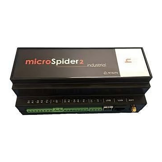
Page 4: Connecting Antenna
Connecting Antenna Connect the antenna lead by screwing the flying lead connector onto the gold antenna “ANT” connector – finger tight only Antenna Connector Connecting Power Connect a 16V – 24V DC, 2A minimum current Power Supply or a 12V Solar Panel to the “Charger” connector. - Page 5 FRONT I/O CONNECTORs (from left to right in previous image) NAME FUNCTION COMMENT SWITCH 1 / COUNTER 1 / DIN1 Active is short to GROUND QUADRATURE 1A 0 – 2.4V or 4-20 mA range AIN1 ANALOGUE 1 GROUND SWITCH 2 / COUNTER 2 / DIN2 Active is short to GROUND QUADRATURE 1B...
- Page 6 Some usage scenarios of the microSpider2 I/O connectors are outlined below: 1. Using the connectors provided, connect Inputs as per manual a. Switch, counter, quadrature and tamper inputs - connected directly to appropriate input and GROUND. b. 4-20mA – connect directly between an available analogue input and GROUND. External resistors are NOT required c.
- Page 7 Connecting the microSpider2 Industrial to your PC 1. Disconnect your computer from your network and turn it on. 2. Connect one end of the red crossover LAN cable into the “LAN” connector of the microSpider2. 3. Connect one end of the white USB cable into the “USB” connector of the microSpider2.
- Page 8 Modem communications can be tested through the web browser by accessing the “Change Settings -> Modem Diagnostics” page. It provides sophisticated interactive diagnostics capable of testing most of the microSpider2 communication features. microSpider2 Industrial Quick Start Guide Revised 26/02/2016 © Halytech 2016 Tel: (02) 8814 5235 Email: sales@halytech.com.au...