
Related Manuals for Panasonic RF-2400


Summary of Contents for Panasonic RF-2400
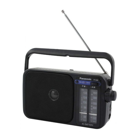
- Page 1 ORDER NO. AD0102029C1 Radio RF-2400 Colour (S)....Silver Type Areas (P)....U.S.A. (PC)..Canada. SPECIFICATIONS Specifications...
-
Page 2: Cabinet Parts Location
Radio Frequency range: 88.0 - 108.0MHz 525 - 1710kHz Intermediate Frequency: 10.7MHz 455kHz Sensitivity: 3.55 V/50mW output / (-3dB limit sens.) V/m/50mW output / (max.sens.) Speaker: 10cm (4”) Output jack: Earphone Power requirement: 120V, 60Hz Battery; DC6V(four R6/LR6, AA, UM-3 batteries) Power consumption: Dimensions (W×H×D):... -
Page 3: Replacement Parts List
2. Replacement Parts List Notes: - Important safety notice: Components identified by mark have special characteristics important for safety. / Furthermore, special parts which have purposes of fire-retardant (resistors), high-quality sound (capacitors), low-noise / (resistors), etc. are used. / When replacing any of components, be sure to use only manufactures specified parts shown in the parts list. -
Page 4: Specifications
ORDER NO. AD0104103C3 FM-AM 2-BAND RECEIVER RF-2400 Colour (S)....Silver Type Areas (GN)..Oceania. SPECIFICATIONS Specifications... -
Page 5: Operation Checks And Component Replacement Procedures
234×122×82mm Mass (without batteries): 670g Play time: (When used at 25°C on a flat, stable surface) Panasonic alkaline dry cell AM; About 47 hours battery: Fm; About 36 hours The play time may be less depending on the operating conditions. - Page 6 components. - For reassembly after operation checks or replacement, reverse the respective procedures. Special reassembly procedures are described only when required. 1.1. Checking for the main P.C.B.
- Page 7 - Check the main P.C.B. as shown below. 1.2. Replacement for the handle - Follow the (Step 1) , (Step 2) of item 1.1.
- Page 8 1.3. Replacement for the speaker - Follow the (Step 1) , (Step 2) of item 1.1. 1.4. Replacement for the dial rope and pointer - Follow the (Step 1) - (Step 4) of item 1.1.
- Page 11 2. Type Illustration of IC’s, Transistors, and Diodes 3. Schematic Diagram 3.1. Schematic Diagram Notes S1-1: BAND switch in “FM” position. S1-2: POWER switch in “ON” position. VR1:...
-
Page 12: Alignment Instructions
Volume control VR. - DC voltage measurements are taken with electronics voltmeter. The negative terminal of the battery provides negative meter connection point. No mark..( )..... - Battery current: Vol. min....FM: 8.8mA (DC) / 3.9mA (AC) AM: 6.0mA (DC) / 3.7mA (AC) Vol. - Page 13 READ CAREFULLY BEFORE ATTEMPTING ALIGNMENT 1. Set power source voltage to 230/240 V AC. 2. Set volume control to maximum. 3. Set band switch to AM, FM or LW. 4. Output of signal generator should be no higher than necessary to obtain an output reading. - AM-IF ALIGNMENT Signal Generator or Sweep Radio Dial Setting...
- Page 14 - FM-RF ALIGNMENT Signal Generator or Sweep Generator Radio Dial Indicator Adjustment Remarks Setting (Electronic (Shown in Fig. 1 Connections Frequency Voltmeter or oscilloscope) Connect to test 86.2 MHz Variable Connect vert. L5 (FM OSC Coil) [*2] point TP1 through capacitor fully amp.
- Page 15 Fig. 2 6. Replacement Parts List Note: - Important safety notice: / Components identified by ; mark have special characteristics important for safety. / Futhermore, special...
- Page 16 parts which have purposes of fireretardant (resistors), high-quality sound (capacitors),low-noise (resistors), etc. are used. / When replacing any of components, be sure to use only manufacture’s specified parts shown in the parts list. - Capacity values are in microfarads ( F) unless specified otherwise, 1K =1,000(ohm), 1M =1,000k(ohm) - The “<IA>”...
- Page 17 Ref. No. Part No. Part Name & Description Remarks RJCW70003 BATTERY TERMINAL(-) RAS10P34-G SPEAKER RGVW0001-S KNOB,FUNCTION RGWW0004-S KNOB,TUNING RGWX0008-1H KNOB,VOLUME RJCW93003 BATTERY TERMINAL(+/-) RKDW0001F-S DIAL PLATE RKHX0001-1H HANDLE RKKW0003-H BATTEY COVER RKSW0019-H BACK CABINET RMEW0002 ANT TERMINAL RMRX0020-2 PVC SHIELD RUQ50ZA SPRING RDDW0001...
- Page 18 Ref. No. Part No. Part Name & Description Remarks RQCB0169 SERVICE CENTER LIST RJA0035-X AC MAINS LEAD ECBT1H470J5 50V 47P F1D1H470A006 ECBT1H5R6KC5 50V 5.6P F1D1H5R6A017 ECFR1C153MR 16V 0.015 ECBT1H101KB5 50V 100P F1D1H101A012 ECBT1H150JC5 50V 15P ECBT0J223NS5 6.3V 0.022U F1DZZ2230002 ECEA1CKS100 16V 10U ECBT1H8R2KC5 50V 8.2P...
- Page 19 Ref. No. Part No. Part Name & Description Remarks LED1 HFR365P TUNNING LED RPKW0028 GIFT BOX RPN1375 CUSHION XZB30X25A04 POLYETHYLENE SHEET BAG PCB1 REPW0009D P.C.B. ASS’Y (RTL) ERDS2FJ821 1/4W 820 ERDS2FJ122 1/4W 1.2K ERDS2FJ152 1/4W 1.5K ERDS2FJ122 1/4W 1.2K ERDS2FJ331 1/4W 330 ERDS2FJ332 1/4W 3.3K...
- Page 20 8. Packaging...
- Page 21 K010400000YH...
- Page 22 TELESCOPIC ANTENNA MAIN CIRCUIT :POSITIVE VOLTAGE LINE :FM SIGNAL LINE :AM SIGNAL LINE 1.2K 2.7P (0.2V) (0V) (6.5V) 1.5V 0.3V 1.3V 1.3V 1.3V 1.3V 1.3V 1.3V 0.5V 3.6V FM FE CXA1619BS DISCRIMINATOR TV/FM/AM FRONT END, IF AMP,DET,AGC & FM IF AF POWER AMP AM FE TUNING...
- Page 23 HFR365P CXA1619BS RVD1SR139TA Cathode Anode Cathode Anode...
-
Page 24: Battery Terminal
Note: This printed circuit board diagram may be modified at any time with the development of new technology. MAIN P.C.B. TELESCOPIC ANTENNA EARPHONE LED P.C.B. (VOL) LED1(TUNING) 1 CF2 VC1-2 1 CF1 VC1-4 POWER/BAND VC1-3 VC1-1 SPEAKER 10cm 4 BATTERY TERMINAL P.C.B.