Table of Contents
Advertisement
Quick Links
Advertisement
Table of Contents

Related Manuals for WDM NE Series


Summary of Contents for WDM NE Series
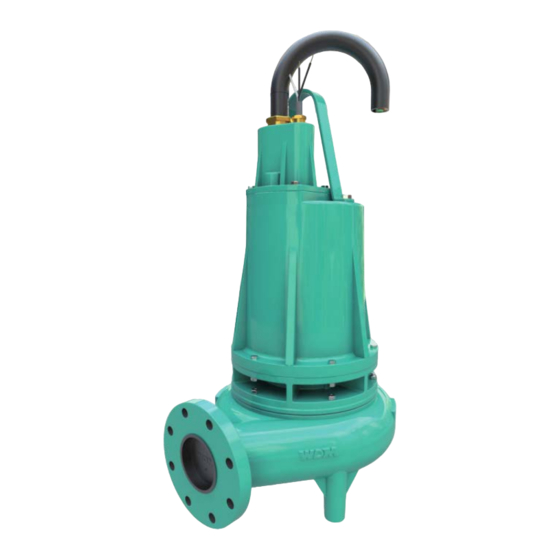
- Page 1 Operation Manual Submersible Non-clog pumps 4” & 6” NE Series.
- Page 2 WDM is not responsible for any damage or accidents that occur when the instructions given in this manual have not been followed. The warranty is only valid when using WDM original spare parts. Failure to follow these guidelines in installing and starting your...
-
Page 3: Safety Recommendations
Wastewater pumps NE, NE 4 and NE 6 are not recommended for use in pools or water recreation facilities. • WDM pumps are designed to operate safely when used and maintained according to this manual. • Rotating parts of the pumps are dangerous and can cause injury. - Page 4 Operation Manual. attempting to lift the pump. • The pump should not be operated without the proper safety devices in place. If such devices are removed during service and repair work, make sure they are replaced before operating the pump again. •...
-
Page 5: Installation
NE Pumps. Installation. Receiving Pumps should be inspected upon receipt. Make note of damage or missing parts, if any, and immediately file a claim with the shipping company. During inspection, if the manual is removed, do not lose or misplace it. Location. -
Page 6: Discharge (Outlet) Piping
Air or gas may get trapped in high points along the piping which retards the pump’s operation. The NE pump is designed to allow installation or removal without requiring personal to enter the well. If need it you can use WDM slide rail system (Sold separately, does not includes rails). -
Page 7: Installation Diagram
NE Pumps. Installation Diagram Control Panel Gate Valve Check Valve ½” Pressure Relief piping Discharge pipe Rail guide Elbow Float controls Liquid level controls: Float controls are supported by mounting a bracket which is attached to the borehole wall, deck, or junction box. Use cable grips to hold the cables in place during instillation. -
Page 8: Overload Protection
ATTENTION. Always use the installed handle, never the cord, to lift the pump. ATTENTION. WDM does not supply all the accessories (valves, gauges, pipes, extensions, etc.) mentioned in this operation manual and installation. ATTENTION. Do not continue to operate the pump if an overload situation arises. - Page 9 NE Pumps. Wire Size A licensed electrician should be consulted to determine what wire size should be used if more power is required. Consult the table for electrical information. Amps Winding Amps (max) at Cable Model Phases resistance (max.) locked size at Start-up rotor...
-
Page 10: Pre-Start Checklist
Operation Manual. Pre-start checklist. To avoid damage to the seal, and to maximize seal life observe the following precautions: • Stay within the temperature or pressure limitations specified for the mechanical seal used. • Do not run the pump dry or against a closed valve! Dry operation will cause seal failure within minutes. -
Page 11: Motor Rotation
NE Pumps. • Perform an insulation (or megger) test on the motor before putting the pump into service. • Resistance values (ohms), voltage, and current (amps) should all be recorded and saved for future reference. Motor rotation. CAUTION. To check the driver rotation, make sure pump and driver couplings are fully disconnected and separated physically. -
Page 12: Starting The Pump
± 5%. Pump shutdown. The following shutdown procedures will apply in most normal shut- downs for the WDM pumps types NE. • Close the discharge gate valve slowly to prevent hydraulic shock, and then cut power to the motor. -
Page 13: Maintenance
NE Pumps. Maintenance. WARNING. If equipment is rotating, do not attempt to complete any maintenance, inspection, repair, or cleaning until rotation has stopped as such actions could result in injury to personnel.. Before attempting any inspection or repair on the pump, the driver controls must be in the “OFF”... -
Page 14: Pressure Test
Operation Manual. Casing Seal chamber Model Gallons Liters Gallons Liters NE 4 450/750/1130/1500 NE 6 9/180/240 15.0 56.8 NE 6 300/480/600/750 11.0 41.6 CAUTION. Do not completely fill the motor casing with oil as this can cause buildup dangerous pressure that may destroy the pump. Allow 1.75”... -
Page 15: Impeller Replacement
NE Pumps. Cleaning. If the pump is used for portable applications, pump clean water through it after each use to prevent deposits of dirt and scale from forming. Impeller replacement. In cleaning out the body (1), replacing the impeller (4), or replacing the wear ring (on NE 6 pumps), disconnect the power, remove any hex screws (13), and then lift the vertical motor and seal out of the body. - Page 16 Operation Manual. Impeller Washer (27) Stud Impeller Motor Housing Washer (27) Gasket Gasket Wear Impeller Ring Bolt Body Body Mounting. To install a new wear ring in the NE 6 apply a retaining compound into the body wear ring housing (26) and press the wear ring in until seated.
- Page 17 NE Pumps. ATTENTION. When installing the pump impeller in a NE 4 unit, check that the clearance between the impeller and the flat face of the body is within 0.010 “(0.25mm) to 0.030” (0.7mm). Servicing Motor and Mechanical Seal: • Remove the body (1) and impeller (4) as stated above.
- Page 18 Operation Manual. Carefully assemble the double seal bracket (3) onto the motor (5) using motor screws. Then tighten the screws and insert into the body housing (16). Secure the coupling with nuts (13) and then add oil as specified above. Double Seal Mechanical Seal (6) Bracket (3)
- Page 19 NE Pumps.
- Page 20 Operation Manual. NE 4...
- Page 21 NE Pumps.
- Page 22 Operation Manual. NE 6...
- Page 23 NE Pumps. Parts List ITEM DESCRIPTION 1 MOTOR 2 MOISTURE SENSOR WIRE 3 GROUNDING 4 SHAFT SEAL 5 GASKET 6 SQUARE RING 7 O-RING 8 MOTOR HOUSING 9 SEAL PLATE 10 DIAPHRAGM 11 CABLE ASSEMBLY 12 DIAPHRAGM CLAMP 13 SOCKET HEAD CAP 14 WASHER 15 HEX NUTS 16 CAP SCREW...
-
Page 24: Troubleshooting
Operation Manual. Trouble Shooting Symptoms Possible cause(s) Possible solution(s) There may not be power to the motor’s Check and correct. connections. Measure the current in the motor terminals as Impeller is blocked by solids larger than it cannot exceed ± 20%. If amps are blocked the pump can handle. - Page 25 NE Pumps. 7. Dimensions NE 4 19.9” 11.7” NE 6 28.6” 16.87”...
- Page 26 Operation Manual. 8. Rail Lift System (Accessory) 1 ½ or 2” Guide Rail Pipe Sch. 40 Optional Pump Body Discharge Flange...
-
Page 27: Warranty
NE Pumps. 9. Warranty. WDM guarantees its NE Pumps for a period of 12 months from the date of delivery, against defects in material and workmanship, according the indicated in its general conditions of sale. Failure to follow the suggestions and recommendations in this manual, as well as improper product use or handling, will completely invalidate the warranty. - Page 28 4034 Mint Way Dallas, Texas 75237 214-337-8780 support@wdmpumps.com...