Mitsubishi Electric A800-E Instruction Manual
Hide thumbs
Also See for A800-E:
- Instruction manual (85 pages) ,
- Instruction manual (101 pages) ,
- Instruction manual (139 pages)
Advertisement
Quick Links
INVERTER
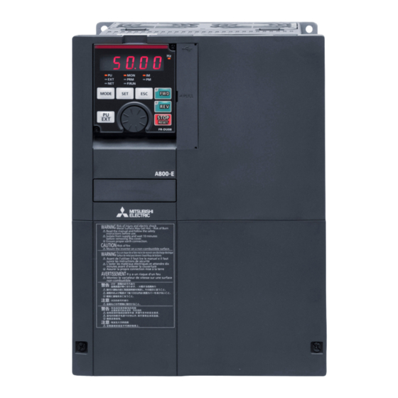
A800-E
FR-A860-E (600V CLASS SPECIFICATION INVERTER)
INSTRUCTION MANUAL (STARTUP)
FR-A860-00027-00450-E-N6
FR-A860-00680-04420-E
Thank you for choosing this Mitsubishi Electric Inverter.
This Instruction Manual and the enclosed CD-ROM give handling information and precautions for use of this
product.
Do not use this product until you have a full knowledge of the equipment, safety information and instructions.
Please forward this Instruction Manual and the enclosed CD-ROM to the end user.
1
INVERTER INSTALLATION AND PRECAUTIONS ...................................................... 5
2
WIRING........................................................................................................................... 7
3
FAILSAFE SYSTEM WHICH USES THE INVERTER ................................................... 9
4
PRECAUTIONS FOR USE OF THE INVERTER ........................................................... 9
5
INVERTER FUNCTION SETTING................................................................................ 11
─CONTENTS─
800
Advertisement

Related Manuals for Mitsubishi Electric A800-E


Summary of Contents for Mitsubishi Electric A800-E
-
Page 1: Table Of Contents
INSTRUCTION MANUAL (STARTUP) FR-A860-00027-00450-E-N6 FR-A860-00680-04420-E Thank you for choosing this Mitsubishi Electric Inverter. This Instruction Manual and the enclosed CD-ROM give handling information and precautions for use of this product. Do not use this product until you have a full knowledge of the equipment, safety information and instructions. - Page 2 This Instruction Manual provides handling information and Injury Prevention precautions for use of the equipment. CAUTION Please forward this Instruction Manual to the end user. The voltage applied to each terminal must be the ones specified in the Safety Instructions Instruction Manual (Detailed).
- Page 3 Application of caution labels WARNING Caution labels are used to ensure safety during use of Mitsubishi Electric inverters. Usage Apply the following labels to the inverter if the "retry function" and/or Stay away from the equipment when the retry function is set as it will "automatic restart after instantaneous power failure"...
- Page 4 MEMO...
-
Page 5: Inverter Installation And Precautions
INVERTER INSTALLATION AND PRECAUTIONS Inverter model • FR-A860-00450 or lower FR - A8 0 00320 Symbol Voltage class Symbol Description Communication Circuit board coating UL Type 1 Symbol Symbol Plated conductor type (conforming to IEC60721-3-3 3C2/3S2) certification 00027 to 00450 Inverter SLD rated current (A) 600 V class Ethernet∗1 With... - Page 6 Accessory • Eyebolt for hanging the inverter Capacity Eyebolt size Quantity FR-A860-02890, 03360 FR-A860-04420 • Brake resistor (1): Enclosed with the FR-A860-00090 or lower • Protective bush (1): Enclosed with the FR-A860-00090 or lower • Earthing (grounding) cable (1): For connection with a communication option •...
-
Page 7: Wiring
Terminal connection diagrams WIRING Terminal connection diagrams FR-A860-00320 Brake resistor ∗7,∗8 DC reactor ∗1 Brake resistor ∗8 DC reactor ∗1 Sink logic Main circuit terminal Control circuit terminal Jumper Earth Jumper (Ground) Earth (Ground) MCCB R/L1 Inrush current Three-phase Motor S/L2 limit circuit AC power T/L3... - Page 8 Main circuit terminals Main circuit terminals Cable gauge of main circuit terminals and earth (ground) terminals Use an appropriate cable gauge to suppress the voltage drop to 2% or less. If the wiring distance is long between the inverter and motor, the voltage drop in the main circuit will cause the motor torque to decrease especially at a low speed. The following table indicates a selection example for the wiring length of 20 m.
-
Page 9: Failsafe System Which Uses The Inverter
When a fault is detected by the protective function, the protective function is activated and output a Fault (ALM) signal. However, the ALM signal may not be output at an inverter's fault occurrence when the detection circuit or output circuit fails, etc. Although Mitsubishi Electric assures the best quality products, provide an interlock which uses inverter status output signals to prevent accidents such as damage to the machine when the inverter fails for some reason. - Page 10 • Electrical corrosion of the bearing When a motor is driven by the inverter, axial voltage is generated on the motor bearing, which may cause electrical corrosion of the bearing in rare cases depending on: condition of the grease used for the bearing, wiring, load, operating conditions of the motor, or specific inverter settings (high carrier frequency).
-
Page 11: Inverter Function Setting
Operation panel (FR-LU08) INVERTER FUNCTION SETTING Operation panel (FR-LU08) The operation panel can be used for setting the inverter parameters, monitoring various items, and checking fault indications. Removal and installation of the accessory cover • Loosen the two fixing screws on the accessory cover. •... - Page 12 Parameter list Parameter list For simple variable-speed operation of the inverter, the initial values of the parameters may be used as they are. Set the necessary parameters to meet the load and operational specifications. Parameter setting, change and check can be performed from the operation panel. Setting Initial Setting...
- Page 13 Parameter list Setting Initial Setting Initial Setting Initial Name Name Name range value range value range value 0.01 to 10s, RT terminal function Current averaging PID differential time 9999 0 to 590Hz, 9999 9999 9999 selection range Electronic bypass AU terminal function Current averaging filter 0, 1 1 to 4000...
- Page 14 Parameter list Setting Initial Setting Initial Setting Initial Name Name Name range value range value range value Creep switchover 0 to 5, 12, 13, First target position 0 to 16383 position 100 to 105, 112, lower 4 digits 113, 1000 to 1005, Position loop First target position 0 to 8191...
- Page 15 Parameter list Setting Initial Setting Initial Setting Initial Name Name Name range value range value range value 100, 111, 112, Reverse rotation Induced voltage 0 to 5000mV/ 9999 121 to 124, 200, excitation current low 0 to 300%, 9999 9999 constant (phi f) (rad/s), 9999 211, 212, 221 to...
- Page 16 Parameter list Setting Initial Setting Initial Setting Initial Name Name Name range value range value range value Torque command 0 to 500A, 9999 Terminal 1 bias 0 to 6 0 to 590Hz Second motor torque source selection frequency (speed) current/Rated PM 9999 Torque command value...
- Page 17 Parameter list Setting Initial Setting Initial Setting Initial Name Name Name range value range value range value Number of analog 1137 Second PID display 0, 1, 2, 10, 11, 1023 1 to 8 0 to 300% channels bias analog value Seventh positioning 12, 100, 101, ...
- Page 18 Parameter list Setting Initial Setting Initial Name Name range value range value Position control Ethernet command 1292 terminal input selection 0, 1 1452 source selection IP 0 to 255 address 4 Roll feeding mode 1293 0, 1 selection Ethernet command source selection IP Position detection lower 1453...
- Page 19 Appendix Appendix 1 Instructions for UL and cUL (Standard to comply with: UL 508C, CSA C22.2 No.274-13) General precaution CAUTION - Risk of Electric Shock - The bus capacitor discharge time is 10 minutes. Before starting wiring or inspection, switch power off, wait for more than 10 minutes, and check for residual voltage between terminal P/+ and N/- with a meter etc., to avoid a hazard of electrical shock.
- Page 20 Appendix 2 Restricted Use of Hazardous Substances in Electronic and Electrical Products The mark of restricted use of hazardous substances in electronic and electrical products is applied to the product as follows based on the “Management Methods for the Restriction of the Use of Hazardous Substances in Electrical and Electronic Products” of the People's Republic of China. 电器电子产品有害物质限制使用标识要求...
- Page 21 4. Exclusion of loss in opportunity and secondary loss from warranty liability Regardless of the gratis warranty term, Mitsubishi Electric shall not be liable for compensation to: Damages caused by any cause found not to be the responsibility of Mitsubishi Electric.
- Page 22 • The copyright and other rights of the enclosed CD-ROM all belong to Mitsubishi Electric Corporation. • No part of the enclosed CD-ROM may be copied or reproduced without the permission of Mitsubishi Electric Corporation. • Specifications of the enclosed CD-ROM are subject to change for modification without notice.
- Page 23 REVISIONS *The manual number is given on the bottom left of the back cover. Revision Date *Manual Number Revision May 2016 IB-0600638ENG-A First edition Nov. 2016 IB-0600638ENG-B Added • Load characteristics fault detection (Pr.1480 to Pr.1492) • Ethernet communication parameters (Pr.313 to Pr.315, Pr.349, Pr.541, Pr.544, Pr.1124, Pr.1125) •...
- Page 24 FR-A800/A800 Plus Series Instruction Manual Supplement Internal storage device fault (E.PE6) The operation of the storage device in the inverter can be checked. If a data fault occurs in the storage device in the inverter, the protective function (E.PE6) is activated. When the read value of Pr.890 is "7"...
- Page 25 GR-18542 Piraeus SE- 223 55 Lund Phone: +30 (0)211 / 1206-900 Phone: +46 (0) 8 625 10 00 Fax: +30 (0)211 / 1206-999 Mitsubishi Electric Turkey Elektrik Ürünleri A.Ş. TURKEY MELTRADE Kft. HUNGARY Fabrika Otomasyonu Merkezi Fertő utca 14. Şerifali Mahallesi Nutuk Sokak No.5 HU-1107 Budapest TR-34775 Ümraniye-İSTANBUL...