Advertisement
Get To Know Your Switch
This chapter contains the following sections:
•
•
•
•
•
•
•
•
•
•
Introduction
Thank you for purchasing the Cisco CBS Series Switch. The Cisco CBS Series Switches combine powerful
network performance and reliability with a complete suite of network features that you need for a solid business
network. These expandable Gigabit Ethernet switches, with Gigabit or 10-Gigabit uplinks, provide multiple
management options, rich security capabilities, and Layer-3 static routing features far beyond those of an
unmanaged or consumer-grade switch, at a lower cost than fully managed switches.
Before You Begin
Before you begin installing your device, ensure that the following items are available:
• RJ-45 Ethernet cables for connecting network devices. A category 6a and higher cable is required for
• Tools for installing the hardware.
Introduction, on page 1
Rack Mounting Switch, on page 2
Wall Mounting a Switch, on page 3
Out-Of-Band Port, on page 5
Stacking the Switches, on page 6
Power over Ethernet Considerations, on page 8
Front Panel, on page 10
Configuring Switches, on page 12
Restoring Factory Default Settings, on page 14
Navigation, on page 15
10G ports; a category 5e and higher cable is required for all other ports.
• The rack-mount kit packed with the switch contains four rubber feet for desktop placement, and
two brackets and twelve screws for rackmounting.
• If the supplied screws are lost, use replacement screws in the following size:
• Diameter of the screw head: 6.9 mm
• Length of face of screw head to base of screw: 5.9 mm
Get To Know Your Switch
1
Advertisement
Table of Contents

Related Manuals for Cisco CBS Series


Summary of Contents for Cisco CBS Series
-
Page 1: Table Of Contents
Navigation, on page 15 Introduction Thank you for purchasing the Cisco CBS Series Switch. The Cisco CBS Series Switches combine powerful network performance and reliability with a complete suite of network features that you need for a solid business network. These expandable Gigabit Ethernet switches, with Gigabit or 10-Gigabit uplinks, provide multiple management options, rich security capabilities, and Layer-3 static routing features far beyond those of an unmanaged or consumer-grade switch, at a lower cost than fully managed switches. -
Page 2: Rack Mounting Switch
Get To Know Your Switch Rack Mounting Switch • Shaft diameter: 3.94 mm Warning To prevent airflow restriction, allow clearance around the ventilation openings to be at least 3 inches (7.6 cm). • A computer to manage the device either via the console port or via the web-based interface. for web based interface the computer needs to support one of the following browsers: •... -
Page 3: Wall Mounting A Switch
Get To Know Your Switch Wall Mounting a Switch Supplied rack mounting for switch models with front mounting position. The mounting ears sit flush to the front panel. Wall Mounting a Switch You can mount the switches on a wall, using wall studs or to a firmly attached plywood mounting backboard. Caution Read these instructions carefully before beginning installation. - Page 4 Get To Know Your Switch Wall Mount an 8 Port Switch Step 3 After the brackets are securely attached, mount the switch with the front panel facing down. Make sure that the switch is attached securely to wall studs or to a firmly attached plywood-mounting backboard. Wall-mounting a 24-port switch. Wall-mounting a 24-port Wall Mount an 8 Port Switch To wall-mount a 8-port switch using mounting screws, follow these steps:...
-
Page 5: Out-Of-Band Port
Get To Know Your Switch Out-Of-Band Port Step 7 Remove the screw template from the wall. Step 8 Place the switch onto the mounting screws, and slide it down until it locks in place.Wall-mounting an 8-port switch Figure 4 Wall-mounting an 8-port switch Out-Of-Band Port The switch supports an Out-of-Band (OOB) port which is used for the management network. -
Page 6: Stacking The Switches
This is the more reason SG series switches cannot be stacked with CBS series switches. CBS250 series switches do not have stacking capabilities. - Page 7 Get To Know Your Switch Feature Support on Hybrid Mode In general, except for the CBS350-48XT-4X, all CBS350 switches that support stacking and have designated uplink ports in their PID can stack natively among themselves, and those that do not have uplink ports, including the CBS350-48T-4X can stack, among themselves, in native mode as well.
-
Page 8: Power Over Ethernet Considerations
Get To Know Your Switch Power over Ethernet Considerations Power over Ethernet Considerations Some switches support PoE while others do not. The switch models that support PoE have a P in their model number, such as: CBSxxx-xxP-xx. If your switch is one of the Power over Ethernet (PoE) models, consider the following power requirement. - Page 9 Get To Know Your Switch Power over Ethernet Considerations SKU Name Description PoE PD Chipset Type PoE PSE Support CBS350-16FP-2G 16-Port Gigabit PoE 2*TPS2388 AF/AT Managed Switch CBS350-24P-4G 24-Port Gigabit PoE 3*TPS2388 AF/AT Managed Switch CBS350-24FP-4G 24-Port Gigabit PoE 3*TPS2388 AF/AT Managed Switch CBS350-48P-4G...
-
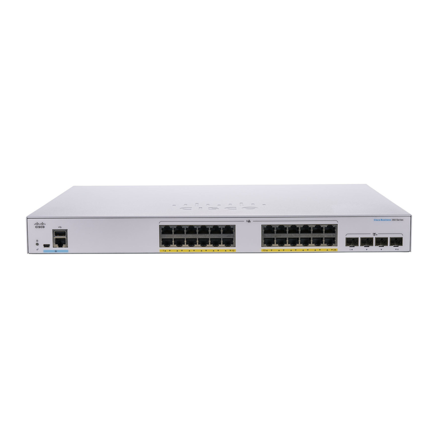
Page 10: Front Panel
These ports are also commonly referred to as mini 10GigaBit Interface Converter ports. The term SFP+ is used in this guide. • The SFP+ ports (if present) are compatible with the following Cisco SFP 1G optical modules MGBSX1, MGBLX1, MGBLH1, MGBT1, as well as other brands. - Page 11 Uplink ports on CBS350-8MGP-2X also support Multi-Gigabit speed. In this case, port speed can reach 10Gbps. Most of the cabling deployed worldwide is Cat5e, and previously limited to 1 Gbps at 100 meters. Cisco Multigigabit Ethernet enables speeds up to 2.5 or 5 Gbps on the same infrastructure without replacing a cable.
-
Page 12: Configuring Switches
The following table shows the default settings used when configuring your switch for the first time. Parameter Default Value Username cisco Password cisco LAN IP 192.168.1.254 Configuring Your Switch Using the Web-based Interface To access the switch with a web-based interface, you must know the IP address that the switch is using. - Page 13 To configure the switch using the console port, which is only supported on ceratin models, proceed with the following steps: Step 1 Connect a computer to the switch console port using a Cisco console cable (purchased separately) or a cable with mini USB connector. Step 2 Start a console port utility such as HyperTerminal on the computer.
-
Page 14: Restoring Factory Default Settings
Console access also provides additional interfaces for debug access which are not available via the web interface. These debug access interfaces are intended to be used by a Cisco Support Team personnel, in cases where it is required to debug device’s behavior. -
Page 15: Navigation
Get To Know Your Switch Navigation • With the power on, press and hold the Reset button for more than ten seconds. Navigation The navigation menu, located at the top right of each UI page, lists the device’s main features.You can access each feature’s UI pages using a series of cascading menus. - Page 16 Get To Know Your Switch Basic or Advanced Display Mode Get To Know Your Switch...