Table of Contents
Advertisement
Quick Links
Cisco Web Security Appliance S195, S395, S695, and S695F Hardware
Installation Guide
First Published: 2019-07-08
Last Modified: 2021-07-19
Americas Headquarters
Cisco Systems, Inc.
170 West Tasman Drive
San Jose, CA 95134-1706
USA
http://www.cisco.com
Tel: 408 526-4000
800 553-NETS (6387)
Fax: 408 527-0883
Advertisement
Table of Contents

Related Manuals for Cisco S195


Summary of Contents for Cisco S195
- Page 1 Cisco Web Security Appliance S195, S395, S695, and S695F Hardware Installation Guide First Published: 2019-07-08 Last Modified: 2021-07-19 Americas Headquarters Cisco Systems, Inc. 170 West Tasman Drive San Jose, CA 95134-1706 http://www.cisco.com Tel: 408 526-4000 800 553-NETS (6387) Fax: 408 527-0883...
- Page 2 Cisco has more than 200 offices worldwide. Addresses and phone numbers are listed on the Cisco website at www.cisco.com/go/offices. Cisco and the Cisco logo are trademarks or registered trademarks of Cisco and/or its affiliates in the U.S. and other countries. To view a list of Cisco trademarks, go to this URL: https://www.cisco.com/c/en/us/about/legal/trademarks.html.
- Page 3 Site Environment Site Considerations Power Supply Considerations Rack Configuration Considerations C H A P T E R 3 Rack-Mount the Chassis Unpack and Inspect the Chassis Rack-Mount the Chassis Cisco Web Security Appliance S195, S395, S695, and S695F Hardware Installation Guide...
- Page 4 Maintenance and Upgrades Power Button Shut Down Enable RPC Reset the Chassis Remotely Install/Uninstall the Locking Faceplate Remove and Replace a Drive Remove and Replace a Power Supply Cisco Web Security Appliance S195, S395, S695, and S695F Hardware Installation Guide...
-
Page 5: Table Of Contents
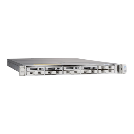
Power Cord Specifications, on page 19 Features The Cisco Web Security Appliances (WSA) S195, S395, S695, and S695F help organizations secure and control web traffic. The WSA S195, S395, S695, and S695F support Cisco AsyncOS version 11.8 and later. See... - Page 6 Overview Features Figure 2: Cisco Web Security S695 and S695F The following table lists the features of the WSA S195, S395, S695, and S695F. Table 1: WSA S195, S395, S695, and S695F Features Feature S195 S395 S695 S695F Form factor...
- Page 7 (RMA). Storage Two 600-GB SAS Four 600-GB SAS Sixteen 600-GB SAS HDDs HDDs HDDs RAID 10, hot-swappable RAID 10, RAID 1, hot-swappable hot-swappable Cisco Web Security Appliance S195, S395, S695, and S695F Hardware Installation Guide...
-
Page 8: Package Contents
Serial Number Locations The serial number (SN) for the WSA S195, S395, S695, and S695F is printed on the pullout asset card located on the front panel as shown in the following figure. Cisco Web Security Appliance S195, S395, S695, and S695F Hardware Installation Guide... - Page 9 Caution The cover latch on the top of the chassis cover is not supported. There are no internal field-replaceable parts in the WSA S195, S395, S695, and S695F. Cisco Web Security Appliance S195, S395, S695, and S695F Hardware Installation Guide...
-
Page 10: Front Panel
Serial number label Cover latch Not supported Front Panel The following figure shows the front panel features and disk-drive configuration for the WSA S195. See Front Panel LEDs, on page 9 for a description of the LEDs. Cisco Web Security Appliance S195, S395, S695, and S695F Hardware Installation Guide... - Page 11 The following figure shows the front panel features and disk-drive configuration for the WSA S395. See Front Panel LEDs, on page 9 for a description of the LEDs. Cisco Web Security Appliance S195, S395, S695, and S695F Hardware Installation Guide...
- Page 12 The following figure shows the front panel features and disk-drive configuration for the WSA S695 and S695F. See Front Panel LEDs, on page 9 for a description of the LEDs. Cisco Web Security Appliance S195, S395, S695, and S695F Hardware Installation Guide...
-
Page 13: Front Panel Leds
Network link activity LED Pullout asset card — Front Panel LEDs The following figure shows the front panel LEDs for the S195, S395, S695, and S695F, and describes their states. Cisco Web Security Appliance S195, S395, S695, and S695F Hardware Installation Guide... - Page 14 • Amber—The chassis is in standby mode. • Blue, flashing—The unit identification • Green—The chassis is in main power mode. function is activated. Power is supplied to all components. Cisco Web Security Appliance S195, S395, S695, and S695F Hardware Installation Guide...
- Page 15 • Green—The chassis is operating at normal temperature. • Amber—One or more temperature sensors breached the critical threshold. • Amber, flashing—One or more temperature sensors breached the nonrecoverable threshold. Cisco Web Security Appliance S195, S395, S695, and S695F Hardware Installation Guide...
-
Page 16: Rear Panel
Overview Rear Panel Rear Panel The following figure shows the rear panel of the WSA S195 and S395. See Rear Panel LEDs, on page 15 a description of the LEDs. Figure 10: S195 and S395 Rear Panel USB 3.0 Type A (USB 1) USB 3.0 Type A (USB 2) - Page 17 The following figure shows the rear panel of the WSA S695F. See Rear Panel LEDs, on page 15 for a description of the LEDs. Cisco Web Security Appliance S195, S395, S695, and S695F Hardware Installation Guide...
- Page 18 SFP-10G-SR (10 Gb) are the only SFP+ transceivers qualified by Cisco. Use only Cisco-qualified SFPs. Note Copper SFPs are not supported. 1050-W AC power supply (PSU 1) 1050-W AC power supply (PSU 2) Cisco Web Security Appliance S195, S395, S695, and S695F Hardware Installation Guide...
-
Page 19: Rear Panel Leds
Rear Panel LEDs The following figure shows the rear panel LEDs of the WSA S195 and describes their states. The S395 is the same except it has two power supplies. The S695 and S695F have the same LEDs except that these models have more data interfaces;... -
Page 20: Power Supply
Power Supply Note Make sure that one power supply is always active. The following table lists the specifications for the 770-W AC power supply (Cisco part number 341-0591-04) used in the WSA S195 and S395. Table 2: 770-W Power Supply Specifications... -
Page 21: Hardware Specifications
Form factor RSP2 Input connector IEC320 C13/C15 The following table lists the specifications for the 1050-W AC power supply (Cisco part number 341-0638-03) used in the WSA S695 and S695F. Table 3: 1050-W Power Supply Specifications Description Specification AC input voltage range Nominal range: 100 to 120 V AC, 200 to 240 V AC Range: 90–132 V AC, 180–264 V AC... -
Page 22: Product Id Numbers
Product ID Numbers The following table lists the PIDs associated with WSA S195, S395, S695, and S695F. The spare components are ones that you can order and replace yourself. If any internal components fail, you must get an RMA for the entire chassis including the SFPs and SFP cables. -
Page 23: Power Cord Specifications
The following power cords and jumper cords are supported. Figure 14: Argentina CAB-250V-10A-AR Plug: IRAM 2073 Cord set rating: 10 A, 250 V Connector: IEC 60320/C13 Cisco Web Security Appliance S195, S395, S695, and S695F Hardware Installation Guide... - Page 24 Plug: NBR 14136 Cord set rating: 10 A, 250 V Connector: IEC 60320/C13 Figure 17: Cabinet Jumper CAB-C13-C14-2M Plug: SS10A Cord set rating: 10A, 250V Connector: HS10S, C-13 to C-14 Cisco Web Security Appliance S195, S395, S695, and S695F Hardware Installation Guide...
- Page 25 Cord set rating: 10 A, 250 V Connector: HS10S, C-13 to C-14 Figure 20: China CAB-250V-10A-CH Plug: GB2099.1/2008 Cord set rating: 10 A, 250 V Connector: IEC 60320/C13 Cisco Web Security Appliance S195, S395, S695, and S695F Hardware Installation Guide...
- Page 26 Plug: IS 6538-1971 Cord set rating: 16 A, 250 V Connector: IEC 60320-C13 Figure 23: Israel CAB-250V-10A-IS Plug: SI-32 Cord set rating: 10 A, 250 V Connector: IEC 60320-C13 Cisco Web Security Appliance S195, S395, S695, and S695F Hardware Installation Guide...
- Page 27 Cord set rating: 12 A, 125 V Connector: IEC 60320/C13 Figure 26: Japan CAB-C13-C14-2M-JP Plug: EN 60320-2-2/E Cord set rating: 10 A, 250 V Connector: EN 60320/C13 to C14 Cisco Web Security Appliance S195, S395, S695, and S695F Hardware Installation Guide...
- Page 28 Plug: NEMA5-15P Cord set rating: 13 A, 125 V Connector: IEC 60320/C15 Figure 29: North America CAB-N5K6A-NA Plug: NEMA6-15P Cord set rating: 10 A, 125 V Connector: IEC 60320/C13 Cisco Web Security Appliance S195, S395, S695, and S695F Hardware Installation Guide...
- Page 29 Cord set rating: 10 A, 250 V Connector: IEC 60320/C15 Figure 32: Taiwan CAB-ACTW Plug: EL 302 (CNS10917) Cord set rating: 10 A, 125 V Connector: IEC 60320/C13 Cisco Web Security Appliance S195, S395, S695, and S695F Hardware Installation Guide...
- Page 30 Overview Power Cord Specifications Figure 33: United Kingdom CAB-9K10A-UK Plug: BS1363A/SS145 Cord set rating: 10 A, 250 V Connector: IEC 60320/C15 Cisco Web Security Appliance S195, S395, S695, and S695F Hardware Installation Guide...
- Page 31 Use the statement number provided at the end of each warning statement to locate its translation in the translated safety warnings for this device. SAVE THESE INSTRUCTIONS Cisco Web Security Appliance S195, S395, S695, and S695F Hardware Installation Guide...
-
Page 32: Installation Warnings
Warning Statement 1019 Main Disconnecting Device The plug-socket combination must be accessible at all times, because it serves as the main disconnecting device. Cisco Web Security Appliance S195, S395, S695, and S695F Hardware Installation Guide... -
Page 33: Safety Recommendations
• Before beginning procedures that require access to the interior of the chassis, locate the emergency power-off switch for the room in which you are working. Then, if an electrical accident occurs, you can act quickly to turn off the power. Cisco Web Security Appliance S195, S395, S695, and S695F Hardware Installation Guide... -
Page 34: Prevent Esd Damage
• Use the chassis within its marked electrical ratings and product usage instructions. • The Cisco Content Security Appliance x95 Series are equipped with an AC-input power supply, which is shipped with a three-wire electrical cord with a grounding-type plug that fits into a grounding-type power outlet only. -
Page 35: Site Considerations
• Be sure enclosed racks have adequate ventilation. Make sure that the rack is not overly congested as each chassis generates heat. An enclosed rack should have louvered sides and a fan to provide cooling air. Cisco Web Security Appliance S195, S395, S695, and S695F Hardware Installation Guide... - Page 36 • Baffles can help to isolate exhaust air from intake air, which also helps to draw cooling air through the chassis. The best placement of the baffles depends on the airflow patterns in the rack. Experiment with different arrangements to position the baffles effectively. Cisco Web Security Appliance S195, S395, S695, and S695F Hardware Installation Guide...
- Page 37 • Effect of damage on the installation Rack-Mount the Chassis Before you begin You can install the chassis in a rack using the Cisco rack kit (part number 800-43376-02). Cisco Web Security Appliance S195, S395, S695, and S695F Hardware Installation Guide...
- Page 38 Install the second inner rail to the opposite side of the chassis. Figure 34: Attach the Inner Rail to the Side of the Server Cisco Web Security Appliance S195, S395, S695, and S695F Hardware Installation Guide...
- Page 39 Slide the release clip toward the rear on both inner rails, and then continue pushing the chassis into the rack until its front slam latches engage with the rack posts Cisco Web Security Appliance S195, S395, S695, and S695F Hardware Installation Guide...
- Page 40 What to do next Install the cables according to your default software configuration as described in the Getting Started Guide for your software version. Cisco Web Security Appliance S195, S395, S695, and S695F Hardware Installation Guide...
- Page 41 To avoid data loss or damage to your operating system, perform a graceful shutdown of the operating system. • Graceful shutdown—Press and release the Power button. The operating system performs a graceful shutdown and the chassis goes into standby mode. The power LED is amber. Cisco Web Security Appliance S195, S395, S695, and S695F Hardware Installation Guide...
- Page 42 Enter commit to save your changes. Step 6 Test your configuration to verify that you can remotely manage chassis power. What to do next Reset the Chassis Remotely, on page 39 Cisco Web Security Appliance S195, S395, S695, and S695F Hardware Installation Guide...
- Page 43 Install/Uninstall the Locking Faceplate The locking faceplate (Cisco part number 74-115098-01 for a 1 RU chassis and Cisco part number 74-115099-01 for a 2 RU chassis) ships with the key you need to lock the faceplate to the front panel of the chassis. The locking faceplate clicks in between the two side handles on the front panel.
- Page 44 You cannot add more drives to the chassis. You can only replace the drives in the slots that are supported for your model. Safety Warnings Take note of the following warnings: Cisco Web Security Appliance S195, S395, S695, and S695F Hardware Installation Guide...
- Page 45 Press the release button on the face of the drive tray. b) Grasp and open the ejector lever and then pull the drive tray out of the slot. Cisco Web Security Appliance S195, S395, S695, and S695F Hardware Installation Guide...
- Page 46 Step 2 Remove the four drive-tray screws that secure the drive to the tray and then lift the drive out of the tray. Figure 39: Remove the Drive Tray Cisco Web Security Appliance S195, S395, S695, and S695F Hardware Installation Guide...
- Page 47 (1+1). Note The S195 ships with one power supply, but you can add another one for redundancy. The chassis also supports cold redundancy. Depending on the power being drawn by the chassis, one power supply might actively provide all power to the system while the remaining power supply is put into a standby state.
- Page 48 Remove the power cord from the power supply that you are replacing. c) Grasp the power supply handle while pinching the release lever toward the handle. d) Pull the power supply out of the bay. Cisco Web Security Appliance S195, S395, S695, and S695F Hardware Installation Guide...
- Page 49 Connect the power cord to the new power supply. d) If you shut down the chassis, press the Power button to return it to main power mode. Cisco Web Security Appliance S195, S395, S695, and S695F Hardware Installation Guide...
- Page 50 Maintenance and Upgrades Remove and Replace a Power Supply Cisco Web Security Appliance S195, S395, S695, and S695F Hardware Installation Guide...