Table of Contents
Advertisement
Quick Links
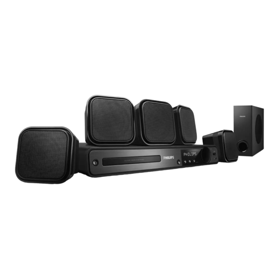
DVD Home Theater System
Service
Service Manual
LASER BEAM SAFETY PRECAUTIONS................................................................................................1-2
STANDARD NOTES FOR SERVICING........................................................................
SAFETY AND IMPORTANT NOTICE......................................................................................................1-7
LOCATION OF PCB BOARDS&VERSION VARIATION .....................................................................2-1
REMOTE CONTROL.............................................................................................................................2-2
OPERATING CONTROLS AND FUNCTIONS .....................................................................................2-3
SPECIFICATIONS ......................................................................................................................................3-1
MEASUREMENT SETUP.................................................................................................... .................... 3-2 .
SYSTEM,REGION CODE,ETC..SETTING PRODURE............................................
RETURN UNIT TEST FLOW......................................................................................................................3-4
MAIN UNIT REPAIR CHART............................................................................................................3-5
DISASSEMBLY INSTRUCTIONS ............................................................................................................4
BLOCK WIRING DIAGRAM.....................................................................................................................5
AMPLIFIER BOARD& LED + KEY BOARD & DECODE BOARD & POWER BOARD......................6
MECHANICAL EXPLODE VIEW&PART LIST......................................................................................10
REVISION LIST.............................................................................................................11
©
Copyright 2009 Philips Consumer Electronics B.V. Eindhoven, The Netherlands
All rights reserved.
No part of this publication may be reproduced, stored in a retrieval system or
transmitted, in any form or by any means, electronic, mechanical, photocopying, or otherwise
without the prior permission of Philips.
Published by LM0909 Service Audio Printed in The Netherlands Subject to modification
Version 1.0
TABLE OF CONTENTS
HTS3021
Chapter
.................1-3
...........
....................3-3
............
GB
3139 785 3483 0
/98/94
Advertisement
Table of Contents

Related Manuals for Philips HTS3021/98


Summary of Contents for Philips HTS3021/98
-
Page 1: Table Of Contents
MECHANICAL EXPLODE VIEW&PART LIST..................10 REVISION LIST…………………………………………………..……………………………....11 © Copyright 2009 Philips Consumer Electronics B.V. Eindhoven, The Netherlands All rights reserved. No part of this publication may be reproduced, stored in a retrieval system or transmitted, in any form or by any means, electronic, mechanical, photocopying, or otherwise without the prior permission of Philips. -
Page 2: Laser Beam Safety Precautions
LASER BEAM SAFETY PRECAUTIONS This DVD player uses a pickup that emits a laser beam. Do not look directly at the laser beam coming from the pickup or allow it to strike against your skin. The laser beam is emitted from the location shown in the figure. When checking the laser diode, be sure to keep your eyes at least 30 cm away from the pickup lens when the diode is turned on. -
Page 3: Standard Notes For Servicing
AC cord. 2. FFC (Flexible Foil Connector) cable should Use only lead-free solder alloy Philips be inserted parallel into the connector, not at SAC305 with order code 0622 149 00106. If an angle. - Page 4 3. The flat pack-IC on the CBA is affixed with On our website glue, so be careful not to break or damage the www.atyourservice.ce.Philips.com you find foil of each pin or the solder lands under the IC more information to: when removing it.
- Page 5 3. Bottom of the flat pack-IC is fixed with glue to the CBA; when removing entire flat pack-IC, first apply soldering iron to center of the flat pack-IC and heat up. Then remove (glue will be melted). (Fig. S-1-6) 4. Release the flat pack-IC from the CBA using tweezers.
- Page 6 2. Ground for Workbench Be sure to place a conductive sheet or copper plate with proper grounding (1 M∧) on the workbench or other surface, where the semi-conductors are to be placed. Because the static electricity charge on clothing will not escape through the body grounding band, be careful to avoid contacting semi-conductors with your clothing.
-
Page 7: Safety And Important Notice
Copyright notice Safety and important notice This product incorporates copyright protection technology that is protected Warning by method claims of certain U.S. patents and other intellectual property rights • Risk of overheating! Never install the Home owned by Macrovision Corporation and Theater System in a confi... - Page 8 LOCATION OF PCB BOARDS DECODE BOARD AMP BOARD POWER BOARD KEY BOARD LED BOARD VERSION VARIATION: HTS3021 Type/Versions Features Χ Χ Output Power-200W Χ Χ Voltage(110V-240V) SERVICE SCNARIO MATRIX: HTS3021 Type/Versions Board in used DECODE board POWER board AMP board LED board KEY board *C=Component Level Repair...
-
Page 9: Remote Control
Remote Control Numeric buttons ( Standby-On ) • Selects an item to play. • Turns on the Home Theater System SUBTITLE or switches to standby mode. • Selects the subtitle language on a disc. (Open/Close ) VOCAL • Opens or closes the disc compartment. -
Page 10: Operating Controls And Functions
OPERATING CONTROLS AND FUNCTIONS Front Panel Standby-On Display Panel Open/Close —Connects a USB — Turns on the player or — Opens or closes the disc Disc Tray supported device switches to standby mode compartment. Play/Pause Stop VOLUME —starts or pauses —Stops playback —... -
Page 11: Specifications
SPECIFICATIONS AMPLIFIER SPEAKERS System ............Full range satellite Total output power ........200 W RMS(10%THD) Frequency Response ......………….180Hz – 18kHz / ±3 dB Speaker impedance ......8 ohm(centre),4 ohm(Front/Rear) Signal-to-Noise Ratio ..........>- 60 dB (A-weighted) Speaker drivers ............ 3” full range speaker Input Sensitivity Frequency response ...........150 Hz –... -
Page 12: Measurement Setup
MEASUREMENT SETUP Tuner FM Bandpass LF Voltmeter 20Hz-15kHz e.g. PM2534 e.g. 7122 707 48001 RF Generator e.g. PM5326 S/N and distortion meter e.g. Sound Technology ST1700B Use a bandpass filter to eliminate hum (50Hz, 100Hz) and disturbance from the pilottone (19kHz, 38kHz). Use Audio Signal Disc SBC429 4822 397 30184 (replaces test disc 3) -
Page 13: System,Region Code,Etc
In open model, press “1“ “5“ “9“ on RC b) Press and select version you want using c) Press and “ok” button to con rm d) TV will show message as below: Current model HTS3021/98 Ver18.04.2M _090211_0 Region Servo: AE.56.00.00 8032: 05.00.04.06 RISC: 05.02.00.24... -
Page 15: Main Unit Repair Chart
MAIN UNIT REPAIR CHART A E AII Function NO Power supply NO ALL Function NO DVD Audio NO Aux/TV in NO Tuner NO Sound Working working Sound Sound Sound A AII Function NO Working Power supply NO ALL Function No Working Sound +27V Voltage No... -
Page 16: Disassembly Instructions
DISASSEMBLY INSTRUCTIONS 1. Disassembly Flowchart This flowchart indicates the disassembly steps to gain access to item(s) to be serviced. When reassembling, follow the steps in reverse order. Bend, route, and dress the cables as they were originally. Top Case Decode Front Power Amplifier... - Page 17 Dismantling of top case 2-1. Ensure no disc in the tray and keep tray close, turn off the DVD player and then disconnect the mains supply. Loosen 6 screws“A” as shown in figure 2-1. Figure 2-1. 2-2. Take off the top case as shown in figure 2-2. OPEN Figure 2-2.
- Page 18 3. Dismantling of led+key board 3-1. Loosen 4 screws “B” as shown in figure 3-1. Figure 3-1...
- Page 19 3-2. Release the lock “C” at the same time as shown figure 3-2. PUSH PUSH PUSH PUSH PUSH Figure 3-2 3-3. Loosen 5 screws “D” as shown in figure 3-3. Figure 3-3...
- Page 20 4. Dismantling of loader 4-1. Loosen 4 screws “E” as shown in figure 4-1. Figure 4-1...
- Page 21 5. Dismantling of de c ode board 5-1. Loosen 5 screws as shown in figure 5-1. Figure 5-1 6. Dismantling of power board 6-1. Loosen 4 screws “G” as shown in figure 6-1. Figure 6-1...
- Page 22 7. Dismantling of amplifier board 7-1. Loosen 4 screw “H” as shown in figure 7-1 Figure 7-1.
- Page 23 8. Dismantling of tuner 8-1. Loosen 1 screws “I” as shown in figure 8-1. Figure 8-1. 9. Dismantling of L ed board 9-1. Loosen 2 screws “J” as shown in figure 9-1. Figure 9-1.
-
Page 24: Block Wiring Diagram
BLOCK WIRING DIAGRAM... - Page 25 AMPLIFIER BOARD SCHEMATIC DIAGRAM 1/3...
- Page 26 AMPLIFIER BOARD SCHEMATIC DIAGRAM 2/3...
- Page 27 AMPLIFIER BOARD SCHEMATIC DIAGRAM 3/3...
- Page 28 AMPLIFIER BOARD TOP VIEW...
- Page 29 AMPLIFIER BOARD BOTTOM VIEW...
- Page 30 LED+KEY BOARD SCHEMATIC DIAGRAM J512 U300 VFDA R534 R527 200780-1A0 R535 R526 R536 10K/ NC 10K/ NC 4 HEADER CB520 CB525 CB526 CB527 ESD/NC 0.1uF CB506 CB533 CB532 3 HEADER CB507 150pF 150pF R518 4.7K R516 Reset STB ON/OFF R519 4/2.0 HEADER -24V IMP810...
- Page 31 LED+KEY BOARD TOP VIEW LED BOARD TOP VIEW KEY BOARD TOP VIEW...
- Page 32 LED+KEY BOARD BOTTOM VIEW...
- Page 33 DECODE BOARD SCHEMATIC DIAGRAM 1/6 RGB_SWITCH: 0--->RGB, 1--->CVBS/YUV YUV[3..6] YUV[3..6] L1541.8uH RGB/YUV Switch YUV4 MUTE_DAC D107 MUTE_DAC R,G,B R298 C191 C192 75,1% DIODE SMD BAV99 Y,U,V 120P AVCC 5V_VIDEO L155 5V_VIDEO RGB_SWITCH CB167 RGB_SWITCH 5V_VIDEO CE125 SCART_L L1561.8uH U113 22uF/10v 0.1uF SCART_L YUV5...
- Page 34 DECODE BOARD SCHEMATIC DIAGRAM 2/6 TUNER_ON TUNER_ON TUNED TUNED STERED STERED I2C_CLK I2C_CLK I2C_DAT I2C_DAT TUNE_L TUNE_L [5] TUNE_R TUNE_R [5] DV33 DV33 [1,2,3,5,7] +12V +12V [1,5,7] -12V -12V [1,5] TUNER_VCC Q114 EC129 CB166 8550 EC130 100U/16v DV33 47U/16v 0.1u R280 R281 R282 4.7K...
- Page 35 DECODE BOARD SCHEMATIC DIAGRAM 3/6 EC111 EC112 U107 U108 CON1 MIC_INL R173 AD_INL MIC_INR R174 AD_INR MIC_DET MIC_DET [2] AUIN1_L AUIN1_R MIC_SW MIC_SW IPOD_L_A C158 4U7/0805 IPOD_R_A C159 4U7/0805 R175 LINE_MUTE1 TUNE_L TUNE_R SCART_L R176 LINE_MUTE1 LINE_MUTE1 [2] AUIN2_L R177 100K 470p AUIN2_R...
- Page 36 DECODE BOARD SCHEMATIC DIAGRAM 4/6 89_MA[0..11] 89_DQ[0..15] 89_MA[0..11] 89_DQ[0..15] 89_BA[0..1] 89_BA[0..1] 89_DQM[0..1] DRAM 89_DQM[0..1] 89_DCLK 89_DCLK 89_DCKE 89_DCKE 89_CAS# 89_AD[0..7] 89_CAS# 89_AD[0..7] 89_RAS# 89_RAS# 89_WE# DV33 89_SD33 FLASH 89_WE# 89_CS# 89_CS# L127 DRAM [2,5] [2,5] 89_PCE# CE123 CB147 CB148 CB149 CB150 CB151 CB152...
- Page 37 DECODE BOARD SCHEMATIC DIAGRAM 5/6 L116 JITFO C110 1000pF JITFN DV33 XTALI RFV33 RFV33 RFVDD3 L118 2.7uH/NC R116 750k ADACVDD L117 150uH C113 C111 2200pF C112 C114 C115 C116 APLLVDD3 L119 47uH 0.1uF/NC CE111 DACVDD3 L120 100uF/6.3v C118 R117 100k 1000pF/NC R118 680k...
- Page 38 DECODE BOARD SCHEMATIC DIAGRAM 6/6 NAME TYPE DEVICE VCC/+5V Digital 5V SUPPLY DV33 Digital 3.3V MT1389HD RFV33 Servo 3.3V MT1389HD AV33 Laser Diode 3.3V Digital 1.8V MT1389HD SD33 Digital 3.3V SDRAM +12V Audio +12V OP AMP. -12V Audio -12V OP AMP. DV33 DV33 URST#...
- Page 39 DECODE BOARD TOP VIEW...
- Page 40 DECODE BOARD BOTTOM VIEW...
- Page 41 POWER BOARD SCHEMATIC DIAGRAM R903 TG901 220R/2W 1K/0.25W R940 R901 L902 D906 C915 F901 680K/1W 680K/1W ET24 15MH UF4007 47U/50V L901 3.5A/250V RV901 ET24 15MH C906 BD901 C903 D4SB460 471K10D 1000P/400V ZD902 R909 5.1V 10K/0.25W D907 C902 NTC901 C916 C901 R941 R902 UF4007...
- Page 42 POWER BOARD TOP VIEW...
- Page 43 POWER BOARD BOTTOM VIEW...
- Page 44 MECHANICAL EXPLODE VIEW...
- Page 45 996510022355 FR.PANEL-ABS/80301/FOILED HL-3 996510022372 MY01-HTS3021/94(HI)POWER BOARD(for/94) 996510022335 MY01-HTS3021/51(HI)POWER BOARD(for/98) 996510021698 FUNCTION BUTTON-ABS/BLACK 8000 996510022375 MY01-HTS3021/94(HI) KEY BOARD(for/94) 996510022337 MY01-HTS3021/98(HI) KEY BOARD(for/98) 996510021715 POWER BUTTON & LED LENS 996510022377 MY01-HTS3021/94(HI)LED BOARD(for/94) 996510022336 MY01-HTS3021/51(HI)LED BOARD(for/98) 996510022159 LOADER ASSY 996510021704 VOLUME BUTTON-ABS/BLACK 80007...
- Page 46 C929 996510004875 CAPACITOR 470PF 1KV +/-10% C934 996510004875 CAPACITOR 470PF 1KV +/-10% C935 996510022126 EC.2200uF 35V +/-20%(105 DEGRE C936 996510022126 EC.2200uF 35V +/-20%(105 DEGRE C940 996500040565 SCC.0.001UF AC250V 400V /-20% CON901 996510022213 180 OEGREE CONNECTOR 2PIN PITC CON902 996520030993 WAFER 2.5mm H X 5 PIN CON903 996510016164 CONNECTOR 2MM H X 6 PIN...
- Page 47 ZD903 996510004909 ZENER DIODE 18V 1/2W ZD904 996510022199 ZENER DIODE 36V 1/2W (TAPE TYP ZD905 996500040221 ZENER DIODE 5V1 1/2W /-5% ZD906 996500040575 ZENER DIODE 12V 1/2W /-5% KEY BOARD 996510021724 90 DEGREE PIN 06+ HOUSING 06+1 996510021738 90 DEGREE PIN 04+90 DEGREE PIN 996510022267 90 DEGREE PIN 03+HOUSING 03+42 996510021736...
- Page 48 CN105 996510016163 CONNECTOR 2mm H X 5 PIN CN106 996510022168 WAFER 2mm H X 3PIN CN111 996510022222 180 DEGREE WAFER PITCH=1.25MM CN120 996510022227 WAFER 2MM H X 7 PIN CN201 996510022187 WAFER 2mm H X 4 PIN CN202 996510022234 RCA JACK X 8 H-TYPE PITCH=14MM CON100 996510019261 CONNECTOR:24PIN...
- Page 49 SMD IC A641604L-6TE AOTOM TSOP U105 996510022325 I.C. MX29LV160DBTI-70G MXIC TS U106 996510022169 I.C. AT24C16N-10SA-2.7C ATMEL U107 996510022265 SMD I. C HEF4051B PHILIPS SO-1 U108 996510022265 SMD I. C HEF4051B PHILIPS SO-1 U109 996510022191 I.C CS5340 CIRRUS LOGIC (101DB U110 996510022236 I.C.
- Page 50 BD801 996510022216 SMD FERRITE BEAD (2 X 1.25mm) BD801A 996510022216 SMD FERRITE BEAD (2 X 1.25mm) BD801B 996510022216 SMD FERRITE BEAD (2 X 1.25mm) 996510021716 PIN 04(3.96)+HOUSING 04(3.96) C801 996500040181 EC.4.7uF 50V-100V /-20% CN802 996510022187 WAFER 2mm H X 4 PIN CN803 996510019261 CONNECTOR:24PIN...
-
Page 51: Revision List
REVISION LIST Version 1.0 *Initial release...