Cisco Nexus 9504 Hardware Installation Manual
Nx-os mode switch
Hide thumbs
Also See for Nexus 9504:
- Hardware installation manual (138 pages) ,
- Configuration manual (11 pages) ,
- Hardware installation manual (8 pages)
Table of Contents
Advertisement
Quick Links
Advertisement
Table of Contents

Related Manuals for Cisco Nexus 9504


Summary of Contents for Cisco Nexus 9504
- Page 1 Cisco Nexus 9504 NX-OS Mode Switch Hardware Installation Guide First Published: March 24, 2014 Last Modified: November 13, 2014 Americas Headquarters Cisco Systems, Inc. 170 West Tasman Drive San Jose, CA 95134-1706 http://www.cisco.com Tel: 408 526-4000 800 553-NETS (6387) Fax: 408 527-0883...
- Page 2 Cisco and the Cisco logo are trademarks or registered trademarks of Cisco and/or its affiliates in the U.S. and other countries. To view a list of Cisco trademarks, go to this URL: www.cisco.com/go/trademarks . Third-party trademarks mentioned are the property of their respective owners. The use of the word partner does not imply a partnership relationship between Cisco and any other company.
-
Page 3: Table Of Contents
C H A P T E R 3 Installing a Rack or Cabinet Unpacking and Inspecting a New Switch Installing the Bottom-Support Rails Installing a Chassis in a Rack or Cabinet Cisco Nexus 9504 NX-OS Mode Switch Hardware Installation Guide... - Page 4 Rebooting a Switch Overview of Supervisor Modules Overview of I/O Module Support Accessing an I/O Module Through a Console Overview of Fabric Modules Overview of Power Modes Power Mode Configuration Guidelines Cisco Nexus 9504 NX-OS Mode Switch Hardware Installation Guide...
- Page 5 3-kW AC Power Cord Specifications LEDs A P P E N D I X B Chassis LEDs System Controller LEDs Supervisor Module LEDs Fan Tray LEDs Fabric Module LEDs I/O Module LEDs Cisco Nexus 9504 NX-OS Mode Switch Hardware Installation Guide...
- Page 6 Contents Power Supply LEDs Accessory Kits A P P E N D I X C Accessory Kit Contents Cisco Nexus 9504 NX-OS Mode Switch Hardware Installation Guide...
-
Page 7: Preface
This preface include the following sections: • Audience, page vii • Documentation Conventions, page vii • Related Documentation for Cisco Nexus 9000 Series NX-OS Software, page viii • Documentation Feedback, page x • Obtaining Documentation and Submitting a Service Request, page x Audience This publication is for hardware installers and network administrators who install, configure, and maintain Cisco Nexus switches. -
Page 8: Related Documentation For Cisco Nexus 9000 Series Nx-Os Software
Related Documentation for Cisco Nexus 9000 Series NX-OS Software The entire Cisco NX-OS 9000 Series documentation set is available at the following URL: http://www.cisco.com/en/US/products/ps13386/tsd_products_support_series_home.html Release Notes The release notes are available at the following URL: http://www.cisco.com/en/US/products/ps13386/prod_release_notes_list.html... - Page 9 Related Documentation for Cisco Nexus 9000 Series NX-OS Software The documents in this category include: • Cisco Nexus 2000 Series NX-OS Fabric Extender Software Configuration Guide for Cisco Nexus 9000 Series Switches • Cisco Nexus 9000 Series NX-OS Fundamentals Configuration Guide •...
-
Page 10: Documentation Feedback
Obtaining Documentation and Submitting a Service Request For information on obtaining documentation and gathering additional information, see the monthly What's New in Cisco Product Documentation, which also lists all new and revised Cisco technical documentation at http://www.cisco.com/en/US/docs/general/whatsnew/whatsnew.html. Open a service request online at https://tools.cisco.com/ServiceRequestTool/create/launch.do. -
Page 11: Overview
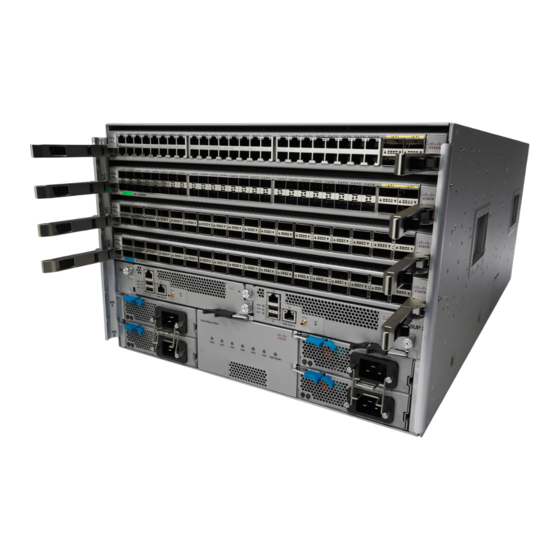
Overview, page 1 Overview The Cisco Nexus 9504 switch chassis (N9K-C9504) holds the following components: • Supervisor modules (one or two supervisor modules of the same type) ◦ Supervisor A with four cores, 1.8 GHz, 16 GB of memory, and 64 GB of SSD (N9K-SUP-A) ◦... - Page 12 Chassis handles (used only for positioning the chassis on the bottom support rails—do modules (one or not use these handles for lifting the chassis) two) in slots SUP 1 and SUP 2 (identified in CLI output as Modules 27 and Cisco Nexus 9504 NX-OS Mode Switch Hardware Installation Guide...
- Page 13 Modules 21 to 26) these handles for lifting the filled chassis) System controllers (two) in slots SC 1 and SC 2 (identified in CLI output as Modules 29 and 30) Cisco Nexus 9504 NX-OS Mode Switch Hardware Installation Guide...
- Page 14 Overview Overview Cisco Nexus 9504 NX-OS Mode Switch Hardware Installation Guide...
-
Page 15: Preparing The Site
However, if the switch is located in an unusually humid location, you should use a dehumidifier to maintain the humidity within an acceptable range. Cisco Nexus 9504 NX-OS Mode Switch Hardware Installation Guide... -
Page 16: Altitude Requirements
• Strong EMI, especially when it is caused by lightning or radio transmitters, can destroy the signal drivers and receivers in the chassis and even create an electrical hazard by conducting power surges through lines into equipment. Cisco Nexus 9504 NX-OS Mode Switch Hardware Installation Guide... -
Page 17: Shock And Vibration Requirements
To plan for the power requirements of a switch, you must determine each of the following: • Power requirements for all of the switch components • Minimum number of power supplies required to power the components installed in the switch Cisco Nexus 9504 NX-OS Mode Switch Hardware Installation Guide... - Page 18 420 W 360 W – 32-port 40-Gigabit QSFP+ I/O module (N9K-X9432PQ) 300 W 240 W Fabric Modules (N9K-C9504-FM) 3 to 6 125 W 100 W Fan Trays (N9K-C9504-FAN) 135 W 110 W Cisco Nexus 9504 NX-OS Mode Switch Hardware Installation Guide...
- Page 19 Typically, power receptacles are placed on the rack with the switch. Power Supply Maximum Distance Between Receptacle and Power Supply All AC power supplies 12 feet (3.5 m) Cisco Nexus 9504 NX-OS Mode Switch Hardware Installation Guide...
-
Page 20: Rack And Cabinet Requirements
These cables must not block access to any removable chassis modules or block airflow into or out of the chassis. Route the cables through the cable management frames on the left and right sides of the chassis. Cisco Nexus 9504 NX-OS Mode Switch Hardware Installation Guide... -
Page 21: Clearance Requirements
For the clearances required for an installation of this chassis, see the following figure. Figure 3: Clearances Required Around the Chassis Chassis Rear service clearance required to replace fan trays and fabric modules Cisco Nexus 9504 NX-OS Mode Switch Hardware Installation Guide... - Page 22 I/O module handles (keep this area clear of rack, cable management, and other components that can prevent full rotation of the ejector levers) No right side clearance required (no airflow on right side) Cisco Nexus 9504 NX-OS Mode Switch Hardware Installation Guide...
-
Page 23: Installing A Chassis
Statement 1018—Supply Circuit Warning Take care when connecting units to the supply circuit so that wiring is not overloaded. Step 1 Bolt the rack to the subfloor before moving the chassis onto it. Cisco Nexus 9504 NX-OS Mode Switch Hardware Installation Guide... -
Page 24: Unpacking And Inspecting A New Switch
• Invoice number of the shipper (see the packing slip) • Model and serial number of the missing or damaged unit • Description of the problem and how it affects the installation Cisco Nexus 9504 NX-OS Mode Switch Hardware Installation Guide... -
Page 25: Installing The Bottom-Support Rails
Be sure there is at least 7.1 RU (12.4 in [31.6 cm]) of vertical space above the rails to install the chassis (see the following figure). Cisco Nexus 9504 NX-OS Mode Switch Hardware Installation Guide... - Page 26 3/4 inch screws for each end of the rail (using a total of 6 screws for the rail as shown in the following figure) and tighten each screw to 40 in-lbs (4.5 N.m) of torque. Figure 5: Attaching Bottom-Support Rails to a Rack Cisco Nexus 9504 NX-OS Mode Switch Hardware Installation Guide...
-
Page 27: Installing A Chassis In A Rack Or Cabinet
Part of this kit has already been used to install the bottom-support rails. You should still have at least 12 12-24 x 3/4-inch or M6 x 19 mm Phillips screws, which are required for attaching the chassis to the rack. Cisco Nexus 9504 NX-OS Mode Switch Hardware Installation Guide... - Page 28 To prevent personal injury or damage to the chassis, never attempt to lift or tilt the chassis using the handles on modules (such as power supplies, fans, or cards); these types of handles are not designed to support the weight of the unit. Cisco Nexus 9504 NX-OS Mode Switch Hardware Installation Guide...
- Page 29 Use at least two persons to push the chassis onto the bottom-support rails and one person to guide the chassis down the center of the rails. Push the lower half of the front side of the chassis so that the back side enters the rack first, and push Cisco Nexus 9504 NX-OS Mode Switch Hardware Installation Guide...
- Page 30 Figure 6: Moving a Chassis onto a Rack or Cabinet Push the sides of the lower half of the front side of Rack vertical mounting rails on the rack. the chassis. Chassis mounting brackets. Bottom support rails Cisco Nexus 9504 NX-OS Mode Switch Hardware Installation Guide...
-
Page 31: Grounding The Chassis
Otherwise, you must connect the chassis grounding pad directly to the data center ground. To connect the switch chassis to the data center ground, you need the following tools and materials: Cisco Nexus 9504 NX-OS Mode Switch Hardware Installation Guide... - Page 32 • Wire-stripping tool to remove the insulation from the grounding wire. Step 1 Use a wire-stripping tool to remove approximately 0.75 inch (19 mm) of the covering from the end of the grounding wire. Cisco Nexus 9504 NX-OS Mode Switch Hardware Installation Guide...
- Page 33 Two M4 screws used to secure the grounding lug to the chassis Grounding cable, with 0.75 in. (19 mm) of insulation stripped from one end, inserted into the grounding lug and crimped in place Cisco Nexus 9504 NX-OS Mode Switch Hardware Installation Guide...
-
Page 34: Connecting The Switch To An Ac Power Source
◦ For combined power mode or power-supply redundancy mode, the power supplies can be installed in any power supply slot in the chassis. ◦ For input-source redundancy mode, the power supplies must be divided into two equal sets and installed as follows: Cisco Nexus 9504 NX-OS Mode Switch Hardware Installation Guide... - Page 35 Verify that the Output Power LED turns on and becomes green. What to Do Next When the power supplies are operating and the switch is fully powered, you are ready to connect the switch to the network. Cisco Nexus 9504 NX-OS Mode Switch Hardware Installation Guide...
- Page 36 Installing a Chassis Connecting the Switch to an AC Power Source Cisco Nexus 9504 NX-OS Mode Switch Hardware Installation Guide...
-
Page 37: Connecting The Switch To The Network
◦ Do not touch the ends of connectors. Touching the ends can leave fingerprints and cause other contamination. Cisco Nexus 9504 NX-OS Mode Switch Hardware Installation Guide... -
Page 38: Connecting A Console To The Switch
◦ Network cabling should already be routed to the location of the installed switch. Step 1 Configure the console device to match the following default port characteristics: • 9600 baud • 8 data bits • 1 stop bit Cisco Nexus 9504 NX-OS Mode Switch Hardware Installation Guide... -
Page 39: Connecting The Management Interface
Step 2 Route the cable through the central slot in the cable management system. Step 3 Connect the other end of the cable to a 10/100/1000 Ethernet port on a network device. Cisco Nexus 9504 NX-OS Mode Switch Hardware Installation Guide... -
Page 40: Creating The Initial Switch Configuration
IP address, which you must provide. You can perform the other configurations at a later time as described in the Cisco Nexus 9000 Series NX-OS Fundamentals Configuration Guide. You should also know the unique name needed to identify the switch among the devices in the network. -
Page 41: Connecting Interface Ports
• You must follow the ESD-preventative protocol, such as wearing a grounded ESD wrist strap, whenever handling electronic components. • You must have BASE-T ports available for connection on a 48-port 10/100/1000 Ethernet I/O module installed on the switch. Cisco Nexus 9504 NX-OS Mode Switch Hardware Installation Guide... -
Page 42: Disconnecting A Base-T Port From The Network
Disconnecting Optical Ports from the Network When removing fiber-optic transceivers, you must remove the fiber-optic cables from a transceiver before removing the transceiver from the port. Cisco Nexus 9504 NX-OS Mode Switch Hardware Installation Guide... -
Page 43: Maintaining Transceivers And Optical Cables
• Inspect routinely for dust and damage. If you suspect damage, clean and then inspect fiber ends under a microscope to determine if damage has occurred. Cisco Nexus 9504 NX-OS Mode Switch Hardware Installation Guide... - Page 44 Connecting the Switch to the Network Maintaining Transceivers and Optical Cables Cisco Nexus 9504 NX-OS Mode Switch Hardware Installation Guide...
-
Page 45: Managing The Switch
You can display information about the switch hardware and the hardware modules installed in the switch chassis by using the show hardware command. switch# show hardware Cisco Nexus Operating System (NX-OS) Software TAC support: http://www.cisco.com/tac Cisco Nexus 9504 NX-OS Mode Switch Hardware Installation Guide... - Page 46 Module type is : Fabric Module 0 submodules are present Model number is N9K-C9504-FM H/W version is 0.1010 Part Number is 73-15287-01 Part Revision is 1 Manufacture Date is Year 17 Week 19 Cisco Nexus 9504 NX-OS Mode Switch Hardware Installation Guide...
- Page 47 0 submodules are present Model number is N9K-SC-A H/W version is 0.2010 Part Number is 73-15294-02 Part Revision is 1 Manufacture Date is Year 17 Week 22 Serial number is SAL17225YG8 CLEI code is Cisco Nexus 9504 NX-OS Mode Switch Hardware Installation Guide...
-
Page 48: Displaying The Hardware Inventory For A Switch
You can display information about the field replaceable units (FRUs), including product IDs, serial numbers, and version IDs by using the show inventory command. switch# show inventory NAME: "Chassis", DESCR: "Nexus9000 C9504 (4 Slot) Chassis " PID: N9K-C9504 VID: V01 , SN: SAL17257PBN Cisco Nexus 9504 NX-OS Mode Switch Hardware Installation Guide... -
Page 49: Displaying The Backplane And Serial Number Information
FRU Minor Type : 0x0 OEM String : Cisco Systems, Inc. Product Number : N9K-C9504 Serial Number : SAL17257PBN Part Number : 73-15298-01 Part Revision Mfg Deviation H/W Version : 0.2010 Mfg Bits Cisco Nexus 9504 NX-OS Mode Switch Hardware Installation Guide... - Page 50 00 00 00 00 00 00 00 00 Second Serial number specific block: Block Signature : 0x6007 Block Version Block Length : 28 Block Checksum : 0x34a Serial Number : SAL17257PBN switch# Cisco Nexus 9504 NX-OS Mode Switch Hardware Installation Guide...
-
Page 51: Displaying Environmental Information For The Switch
------------------------------------------------------ Model Status ------------------------------------------------------ Fan1(sys_fan1) N9K-C9504-FAN 0.5020 Fan2(sys_fan2) N9K-C9504-FAN 0.5020 Fan3(sys_fan3) N9K-C9504-FAN 0.5010 Fan_in_PS1 Fan_in_PS2 None Fan_in_PS3 None Fan_in_PS4 None Fan Zone Speed: Zone 1: 0x0 Fan Air Filter : NotSupported Cisco Nexus 9504 NX-OS Mode Switch Hardware Installation Guide... -
Page 52: Displaying The Current State Of A Module
The hardware has electrical power. When the hardware is powered up, the software begins booting. testing The module has established connection with the supervisor and the module is performing bootup diagnostics. initializing The diagnostics have completed successfully and the configuration is being downloaded. Cisco Nexus 9504 NX-OS Mode Switch Hardware Installation Guide... - Page 53 00-00-00-00-00-00 to 00-00-00-00-00-00 SAL17194HVX 00-00-00-00-00-00 to 00-00-00-00-00-00 SAL17194HRK 00-00-00-00-00-00 to 00-00-00-00-00-00 SAL17194HSR 00-22-bd-f6-9d-58 to 00-22-bd-f6-9d-69 SAL17184072 00-22-bd-fc-04-b0 to 00-22-bd-fc-04-c1 SAL1739DAUL 00-00-00-00-00-00 to 00-00-00-00-00-00 SAL17225YFS 00-00-00-00-00-00 to 00-00-00-00-00-00 SAL17225YG8 * this terminal session switch# Cisco Nexus 9504 NX-OS Mode Switch Hardware Installation Guide...
-
Page 54: Displaying Temperatures For A Module
◦ If you do not have a standby supervisor module in your switch, you have up to 2 minutes to decrease the temperature. During this interval, the software monitors the temperature every 5 seconds and continuously sends system messages as configured. Cisco Nexus 9504 NX-OS Mode Switch Hardware Installation Guide... -
Page 55: Connecting To A Module
Use the attach module slot_number command to get direct access to a specific module. This example shows how to attach to the supervisor in slot 28. switch# attach module 28 Attaching to module 28 ... Cisco Nexus 9504 NX-OS Mode Switch Hardware Installation Guide... -
Page 56: Saving The Module Configuration
A particular switching module is reloaded when you The configured module information is preserved. enter the reload module slot_number command. Cisco Nexus 9504 NX-OS Mode Switch Hardware Installation Guide... -
Page 57: Shutting Down Or Starting Up A Module
For example, suppose that you create an IP storage configuration with an I/O module in slot 3 of Switch A. This module uses an IP address. You decide to remove this I/O module and move it to Switch B, and you no Cisco Nexus 9504 NX-OS Mode Switch Hardware Installation Guide... -
Page 58: Displaying Power Usage Information
3000.00 W Total Power Output (actual draw) 517.00 W Total Power Input (actual draw) 566.00 W Total Power Allocated (budget) 1728.24 W Total Power Available for additional modules 1271.76 W switch# Cisco Nexus 9504 NX-OS Mode Switch Hardware Installation Guide... -
Page 59: Power Cycling A Module
Step 1 Use the configure terminal command to enter the global configuration mode. Example: switch# configure terminal switch(config)# Step 2 Use the copy running-config startup-config command to save the running configuration. Cisco Nexus 9504 NX-OS Mode Switch Hardware Installation Guide... -
Page 60: Overview Of Supervisor Modules
• sup-1 refers to the supervisor module in the SUP 1 slot (slot 27 in the CLI output). • sup-2 refers to the supervisor module in the SUP 2 slot (slot 28 in the CLI output. Cisco Nexus 9504 NX-OS Mode Switch Hardware Installation Guide... -
Page 61: Overview Of I/O Module Support
• 36-port 40-Gigabit QSFP+ aggregation (non-blocking) I/O module (N9K-X9636PQ) • 36-port 40-Gigabit QSFP+ I/O module (N9K-X9536PQ) • 32-port 40-Gigabit QSFP+ I/O module (N9K-X9432PQ) The slots are labeled as LC 1 to LC 4. Note Cisco Nexus 9504 NX-OS Mode Switch Hardware Installation Guide... -
Page 62: Accessing An I/O Module Through A Console
You can troubleshoot bootup problems for an I/O module by accessing the module through its console port. This action establishes a console mode that you must exit in order to use other Cisco NX-OS commands. To attach to the console port for an I/O module, use the attach console module command to specify the module that you need to work with. -
Page 63: Overview Of Power Modes
3 kW. If you have two power grids, you use grid A to power two 3-kW power supplies that provide the available power for the switch and you use grid B to power the other two 3-kW power supplies that provide the reserve power in case grid A fails. Cisco Nexus 9504 NX-OS Mode Switch Hardware Installation Guide... -
Page 64: Power Mode Configuration Guidelines
5.2 kW 3.0 kW 3.0 kW 6.0 kW — Available power exceeds the power requirement for the switch, so the entire switch can power Cisco Nexus 9504 NX-OS Mode Switch Hardware Installation Guide... - Page 65 5.2 kW 3.0 kW 3.0 kW 3.0 kW 6.0 kW 3.0 kW Available power exceeds the power requirement for the switch, so the entire switch can power up. Cisco Nexus 9504 NX-OS Mode Switch Hardware Installation Guide...
- Page 66 3.0 kW 3.0 kW 3.0 kW 3.0 kW 6.0 kW 6.0 kW Available power (6.0 kW) exceeds the power requirement for the switch (5.2 kW), so the entire switch can power up. Cisco Nexus 9504 NX-OS Mode Switch Hardware Installation Guide...
-
Page 67: Setting The Power Mode
When a fan fails or when you remove a fan tray, the remaining operating fans speed up to compensate for Note the loss of fans. This process can increase the noise made by the fan trays until you replace the missing fan tray or replace the defective fan tray. Cisco Nexus 9504 NX-OS Mode Switch Hardware Installation Guide... -
Page 68: Displaying The Status For The Fan Trays
Model Status ------------------------------------------------------ Fan1(sys_fan1) N9K-C9504-FAN 0.5020 Fan2(sys_fan2) N9K-C9504-FAN 0.5020 Fan3(sys_fan3) N9K-C9504-FAN 0.5010 Fan_in_PS1 Fan_in_PS2 None Fan_in_PS3 None Fan_in_PS4 None Fan Zone Speed: Zone 1: 0x0 Fan Air Filter : NotSupported switch# Cisco Nexus 9504 NX-OS Mode Switch Hardware Installation Guide... -
Page 69: Replacing Or Installing Modules, Fan Trays, And Power Supplies
Attach the alligator clip on the other end of the strap to the grounding cable for the switch or to the screws holding the grounding cable to the switch. Step 3 Verify that the grounding cable is attached to the facility earth ground. Cisco Nexus 9504 NX-OS Mode Switch Hardware Installation Guide... -
Page 70: Installing Or Replacing A Supervisor Module
Slide the middle section of the ejector handle toward the end of the handle and rotate the handle away from the front of the module (see Callouts 1 and 2 in the following figure). Cisco Nexus 9504 NX-OS Mode Switch Hardware Installation Guide... - Page 71 Hold the front of the module with one hand and place your other hand under the module to support its weight. c) Align the back of the module to the guides in the open supervisor slot and slide the module all the way into the slot (see the following figure). Cisco Nexus 9504 NX-OS Mode Switch Hardware Installation Guide...
- Page 72 The module stops when its front is about 0.25 inches (0.6 cm) outside the front of the chassis. Figure 9: Installing a Supervisor Module from a Chassis Slide the middle handle toward the end of the Rotate the ejector lever to the front of the chassis. ejector lever. Cisco Nexus 9504 NX-OS Mode Switch Hardware Installation Guide...
-
Page 73: Installing Or Replacing A System Controller Module
Warning Statement 1034—Backplane Voltage Hazardous voltage or energy is present on the backplane when the system is operating. Use caution when servicing Cisco Nexus 9504 NX-OS Mode Switch Hardware Installation Guide... - Page 74 Slide the module all the way into the slot. Cisco Nexus 9504 NX-OS Mode Switch Hardware Installation Guide...
-
Page 75: Installing Or Replacing An I/O Module
Invisible laser radiation may be emitted from disconnected fibers or connectors. Do not stare into beams or view directly with optical instruments. Before You Begin • You must wear an electrostatic discharge (ESD) wrist strap or other ESD protective device while handling modules. Cisco Nexus 9504 NX-OS Mode Switch Hardware Installation Guide... - Page 76 Hold the front of the module with one hand and place your other hand under the module to support its weight. c) Align the back of the module to the guides in the open I/O module slot and slide the module all the way into the slot (see the following figure). Cisco Nexus 9504 NX-OS Mode Switch Hardware Installation Guide...
- Page 77 Verify that the I/O module LEDs turn on and appear as follows: • The Status (STS) LED turns on and becomes green. • For each connected port, the port LED turns on and becomes green or amber. Cisco Nexus 9504 NX-OS Mode Switch Hardware Installation Guide...
-
Page 78: Replacing A Fan Tray
• You must wear an electrostatic discharge (ESD) wrist strap or other ESD protective device while handling modules. • Prepare an antistatic surface or packing materials for each module that you remove from the chassis. Cisco Nexus 9504 NX-OS Mode Switch Hardware Installation Guide... - Page 79 Hold both handles on the front of the fan tray with both of your hands and pull the fan tray out of the slot. Step 3 Set the fan tray on antistatic material or inside an antistatic bag. Cisco Nexus 9504 NX-OS Mode Switch Hardware Installation Guide...
-
Page 80: Installing A Fan Tray
Slide the fan tray all the way into the slot. Cisco Nexus 9504 NX-OS Mode Switch Hardware Installation Guide... -
Page 81: Replacing A Fabric Module
Table 2: Fabric Module Slots to Fill Number of Fabric Modules Slots to be Filled 1 (Not allowed) N.A. 2 (Not recommended) N.A. 3 (Minimum recommended number) 22, 24, and 26 22, 23, 24, and 26 Cisco Nexus 9504 NX-OS Mode Switch Hardware Installation Guide... -
Page 82: Removing A Fabric Module
If the module is damaged, alert the Technical Assistance Center (TAC) and stop this replacement process until you have an undamaged module to install. Step 2 Remove the fan tray that covers the fabric module by following these steps: Cisco Nexus 9504 NX-OS Mode Switch Hardware Installation Guide... - Page 83 6 on the chassis). b) Verify that the Fabric LED for the slot that you specified turns off. Step 4 Remove the fabric module that you are replacing by following these steps: Cisco Nexus 9504 NX-OS Mode Switch Hardware Installation Guide...
- Page 84 Rotate the two handles at least 30 degrees so that the other end of each handle no longer holds the module in the slot (see Callout 2 in the previous figure). Cisco Nexus 9504 NX-OS Mode Switch Hardware Installation Guide...
- Page 85 Rotate the module 90 degrees and lay it flat on an antistatic surface or in an antistatic bag. What to Do Next You are ready to install a fabric module into the open slot (see t_n95xx_install_fabric.xml. Cisco Nexus 9504 NX-OS Mode Switch Hardware Installation Guide...
-
Page 86: Installing A Fabric Module
Be sure that the locking posts fully rotate down into Slide the module all the way into the slot. the module Cisco Nexus 9504 NX-OS Mode Switch Hardware Installation Guide... - Page 87 Figure 19: Installing a Fan Tray in the Chassis Hold the two fan tray handles with your two hands. Screw in four captive screws and tighten each screw to 8 in-lb (0.9 N·m) of torque. Cisco Nexus 9504 NX-OS Mode Switch Hardware Installation Guide...
-
Page 88: Installing A 3-Kw Ac Power Supply
Statement 1034—Backplane Voltage Warning Hazardous voltage or energy is present on the backplane when the system is operating. Use caution when servicing Cisco Nexus 9504 NX-OS Mode Switch Hardware Installation Guide... -
Page 89: Before You Begin
Slide the middle of the ejector lever down to the end of the lever and rotate the lever up so that its other end no longer holds onto the chassis (see the following figure). The power supply unlocks from the chassis and moves out slightly. Figure 20: Removing a Power Supply from the Chassis Cisco Nexus 9504 NX-OS Mode Switch Hardware Installation Guide... - Page 90 (see the following figure). Figure 21: Installing a Power Supply in a Chassis Cisco Nexus 9504 NX-OS Mode Switch Hardware Installation Guide...
- Page 91 The power cables for slots 1 and 2 must be connected to one power source and the power cables in slots 3 and 4 must be connected to another power source. i) Verify that the OK LED turns on and eventually becomes green. Cisco Nexus 9504 NX-OS Mode Switch Hardware Installation Guide...
- Page 92 Replacing or Installing Modules, Fan Trays, and Power Supplies Installing a 3-kW AC Power Supply Cisco Nexus 9504 NX-OS Mode Switch Hardware Installation Guide...
-
Page 93: Appendix A System Specifications
50 to 140°F (10 to 60°C) transceivers) Ambient nonoperating –40 to 158°F (–40 to 70°C) Relative humidity Ambient (noncondensing) 5 to 95% Altitude Operating 0 to 13,123 feet (0 to 4,000 meters) Cisco Nexus 9504 NX-OS Mode Switch Hardware Installation Guide... -
Page 94: Switch Dimensions
– 36-port 40-Gigabit QSFP+ aggregation I/O module (N9K-X9636PQ) 11.5 lb (5.2 kg) – 36-port 40-Gigabit QSFP+ I/O module (N9K-X9536PQ) 12.0 lb (5.4 kg) – 32-port 40-Gigabit QSFP+ I/O module (N9K-X9432PQ) 10.9 lb (4.9 kg) Cisco Nexus 9504 NX-OS Mode Switch Hardware Installation Guide... -
Page 95: Power Requirements For Switch Modules And Fan Trays
– Supervisor A module (N9K-SUP-A) 80 W 69 W – Supervisor B module (N9K-SUP-B) 90 W 75 W System Controller Modules — — – System Controller (N9K-SC-A) 13 W Cisco Nexus 9504 NX-OS Mode Switch Hardware Installation Guide... -
Page 96: Maximum Power Available To The Switch
Supplies Redundancy Mode Redundancy Mode 1 input (220 V) 3000 W — — 6000 W 3000 W 3000 W 9000 W 6000 W 3000 W 12000 W 9000 W 6000 W Cisco Nexus 9504 NX-OS Mode Switch Hardware Installation Guide... -
Page 97: Transceivers, Connectors, And Cables
To comply with GR-1089 intrabuilding, lightning immunity requirements, you must use a foil twisted-pair Caution (FTP) cable that is properly grounded at both ends. The following figure shows the RJ-45 connector. Figure 22: RJ-45 Connector Pin 1 Pin 2 Cisco Nexus 9504 NX-OS Mode Switch Hardware Installation Guide... -
Page 98: 3-Kw Ac Power Cord Specifications
16A, 250 VAC China Continental Europe CAB-AC-2500W-EU 16A, 250 VAC International CAB-AC-2500W-INT 16A, 250 VAC Israel CAB-AC-2500W-ISRL 16A, 250 VAC Japan and North CAB-AC-2500W-US1 16A, 250 VAC America (non locking) 200-240 VAC operation Cisco Nexus 9504 NX-OS Mode Switch Hardware Installation Guide... - Page 99 16A, 250 VAC America (locking) 200-240 VAC operation Power distribution unit CAB-C19-CBN 16A, 250 VAC (PDU) Switzerland CAB-ACS-16 16A, 250 VAC North America CAB-L520P-C19-US NEMA L5-20 to IEC-C19 6 feet (1.8 m) Cisco Nexus 9504 NX-OS Mode Switch Hardware Installation Guide...
- Page 100 System Specifications 3-kW AC Power Cord Specifications Cisco Nexus 9504 NX-OS Mode Switch Hardware Installation Guide...
-
Page 101: Leds
Supervisor modules are all operational. Amber Check the Supervisor Module LEDs for more information. Green Fabric modules are all operational. Amber Check the FAB LED description in the Fan Tray LEDs for more information. Cisco Nexus 9504 NX-OS Mode Switch Hardware Installation Guide... -
Page 102: System Controller Leds
This module is not being identified. Green This module is operational. Flashing This module is booting up. amber Flashing Temperature exceeds major alarm threshold. The module is not receiving power. Cisco Nexus 9504 NX-OS Mode Switch Hardware Installation Guide... -
Page 103: Supervisor Module Leds
The management port is linked up. LINK) The management port is not linked up. (management port Green The management port is linked up. ACT) The management port is not linked up. Cisco Nexus 9504 NX-OS Mode Switch Hardware Installation Guide... -
Page 104: Fan Tray Leds
(bottom LED) Green The fabric module is operational. Flashing red The fabric module has a fault. Flashing The fabric module is booting up. amber No power is going to the fabric module. Cisco Nexus 9504 NX-OS Mode Switch Hardware Installation Guide... -
Page 105: I/O Module Leds
Orange The port is disabled by the operator or is not initializing. Flashing orange The port is faulty and disabled. The port is not active or the link is not connected. Cisco Nexus 9504 NX-OS Mode Switch Hardware Installation Guide... -
Page 106: Power Supply Leds
Power supply is installed without a connection to a power source. seconds) then amber Amber Power supply failure—possibly one of the following conditions: • Over voltage • Over current • Over temperature • Power supply fan failure Cisco Nexus 9504 NX-OS Mode Switch Hardware Installation Guide... - Page 107 Rack-Mount Kit (N9K-C9504-RMK) 1 kit • 12-24 x 3/4-in. Phillips screws (24) • M6 x 19 mm Phillips screws (24) • Adjustable bottom-support rails (2) RJ-45 rollover cable DB-9F/RJ-45F PC terminal Cisco Nexus 9504 NX-OS Mode Switch Hardware Installation Guide...
- Page 108 Cisco Information Packet Not applicable 1-Year Limited Warranty for Hardware If you do not receive a part listed in this document, contact Cisco Technical Support at this URL: Note http://www.cisco.com/warp/public/687/Directory/DirTAC.shtml. If you purchased this product through a Cisco reseller, you might receive additional contents in your kit, such as documentation, hardware, and power cables.
- Page 109 • CAB-AC-2500W-US1—power cord, 250-VAC 16A, straight-blade NEMA 6 • CAB-AC-C6K-TWLK—power cord, 250-VAC 16A, twist lock, NEMA L6-20 • CAB-C19-CBN—cabinet jumper power cord, 250-VAC, 16A, C20C • CAB-ACS-16—power cord, 16-A, Switzerland • CAB-L520P-C19-US—NEMA L5-20 to IEC-C19, 6 ft, US Cisco Nexus 9504 NX-OS Mode Switch Hardware Installation Guide...
- Page 110 Accessory Kits Accessory Kit Contents Cisco Nexus 9504 NX-OS Mode Switch Hardware Installation Guide...