D-Link DGS-1210-20 Reference Manual
Hide thumbs
Also See for DGS-1210-20:
- Reference manual (109 pages) ,
- Reference manual (113 pages) ,
- Manual (171 pages)
Table of Contents
Advertisement
Quick Links
Advertisement
Table of Contents

Related Manuals for D-Link DGS-1210-20


Summary of Contents for D-Link DGS-1210-20
-
Page 2: Table Of Contents
Table of Contents D-Link Web Smart Switch User Manual Table of Contents Table of Contents ............................. i About This Guide ............................. 1 Terms/Usage ..............................1 Copyright and Trademarks ..........................1 Product Introduction ........................... 2 DGS-1210-20 ..............................3 Front Panel ..............................3 Rear Panel .............................. -
Page 3: Table Of Contents
System > Time Profile ..........................29 System > Power Saving ........................... 30 System > IEEE802.3az EEE Settings ...................... 31 System > D-Link Discover Protocol Settings .................... 31 VLAN > 802.1Q VLAN ..........................32 VLAN > 802.1Q VLAN PVID ........................32 VLAN >... - Page 4 Table of Contents D-Link Web Smart Switch User Manual L2 Functions > LLDP > LLDP Management Address Settings ..............50 L2 Functions > LLDP > LLDP Management Address Table ..............51 L2 Functions > LLDP > LLDP Local Port Table ..................51 L2 Functions >...
- Page 5 Table of Contents D-Link Web Smart Switch User Manual To connect a switch via TELNET: ........................ 87 Logging on to the Command Line Interface: ....................87 CLI Commands: ............................87 ? ................................88 download ..............................88 upload ............................... 89 config ipif system ............................90 config ipif system ............................
-
Page 6: About This Guide
Reproduction in any manner whatsoever without the written permission of D-Link Corporation is strictly forbidden. Trademarks used in this text: D-Link and the D-LINK logo are trademarks of D-Link Corporation; Microsoft and Windows are registered trademarks of Microsoft Corporation. Other trademarks and trade names may be used in this document to refer to either the entities claiming the marks and names or their products. -
Page 7: Product Introduction
The SmartConsole easily allows customers to discover multiple D-Link web smart switches with the same L2 network segment connected to the user’s local PC. With this utility, users do not need to change the IP address of the PC and provide easy initial settings of the smart switches. -
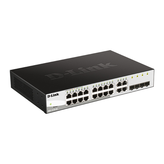
Page 8: Dgs-1210-20
1 Product Introduction D-Link Web Smart Switch User Manual the switches with other third-party devices for management in an SNMP-enabled environment. D-Link Web Smart Switches also come with the D-View plug-in module that works with D-View 6 SNMP Management Software, and provides easy-to-use graphic interface and facilitates the operation efficiency. -
Page 9: Rear Panel
1 Product Introduction D-Link Web Smart Switch User Manual Power LED : The Power LED lights up when the Switch is connected to a power source. Port Link/Act/Speed LED (1-24): The Link/Act/Speed LED flashes, which indicates a network link through the corresponding port. -
Page 10: Rear Panel
1 Product Introduction D-Link Web Smart Switch User Manual Rear Panel Figure 1.4 – DGS-1210-28P Rear Panel Power: Connect the supplied AC power cable to this port DGS-1210-52 48-Port 10/100/1000Mbps plus 4 SFP Slot Web Smart Switch. Front Panel Figure 1.5 – DGS-1210-52 Front Panel Power LED : The Power LED lights up when the Switch is connected to a power source. -
Page 11: Hardware Installation
Screws and two mounting brackets One Multi-lingual Getting Started Guide One CD with User Manual, D-Link Network Assistant (DNA) Utility program, D-Link Network Assistant User Guide and D-View Module If any item is found missing or damaged, please contact the local reseller for replacement. -
Page 12: Step 3 : Plugging In The Ac Power Cord With Power Cord Clip
2 Hardware Installation D-Link Web Smart Switch User Manual Then, use the screws provided with the equipment rack to mount the switch in the rack. Figure 2.3 – Mount the Switch in the rack or chassis Please be aware of following safety Instructions when installing: A) Elevated Operating Ambient - If installed in a closed or multi-unit rack assembly, the operating ambient temperature of the rack environment may be greater than room ambient. - Page 13 2 Hardware Installation D-Link Web Smart Switch User Manual Figure2.4 – Insert Tie Wrap to the Switch B) Plug the AC power cord into the power socket of the Switch. Figure 2.5 – Connect the power cord to the Switch C) Slide the Retainer through the Tie Wrap until the end of the cord.
- Page 14 2 Hardware Installation D-Link Web Smart Switch User Manual D) Circle the tie of the Retainer around the power cord and into the locker of the Retainer. Figure 2.7 – Circle around the power cord E) Fasten the tie of the Retainer until the power cord is secured.
-
Page 15: Power Failure
2 Hardware Installation D-Link Web Smart Switch User Manual Figure 2.9 – Plugging the switch into an outlet Power Failure As a precaution, the switch should be unplugged in case of power failure. When power is resumed, plug the switch back in. -
Page 16: Getting Started
However, if you want to manage multiple D-Link Web Smart Switches, the D-Link Network Assistant (DNA) is a more convenient choice. By using the D-Link Network Assistant (DNA), you do not need to change the IP address of your PC and it is easier to initialize multiple Smart Switches. -
Page 17: Login Web-Based Management
English. Figure 3.3 – Logon Dialog Box Smart Wizard After a successful login, the Smart Wizard will guide you through essential settings of the D-Link Web Smart Switch. Please refer to the Smart Wizard Configuration section for details. Web-based Management By clicking the Exit button in the Smart Wizard, you will enter the Web-based Management interface. - Page 18 3 Getting Started D-Link Web Smart Switch User Manual NOTE: Please be sure to uninstall any existing DNA from your PC before installing the latest DNA. For detailed explanations of the DNA functions, please refer to D-Link Network Assistant (DNA) User Guide.
-
Page 19: Configuration
4 Configuration D-Link Web Smart Switch User Manual Configuration The features and functions of the D-Link Web Smart Switch can be configured for optimum use through the Web-based Management Utility. Smart Wizard Configuration After a successful login, the Smart Wizard will guide you through essential settings of the D-Link Web Smart Switch. -
Page 20: Snmp
4 Configuration D-Link Web Smart Switch User Manual Figure 4.2 – Password in Smart Wizard SNMP The SNMP Setting allows you to quickly enable/disable the SNMP function. The default SNMP Setting is Disabled. Click Enabled and then click Apply to make it effective. - Page 21 4 Configuration D-Link Web Smart Switch User Manual Figure 4.4 – Confirm the changes of IP address in Smart Wizard...
-
Page 22: Web-Based Management
Logout button first, then it will be seen as an abnormal exit and the login session will still be occupied. Finally, by clicking on the D-Link logo at the upper-left corner of the screen you will be redirected to the local D-Link website. -
Page 23: Tool Bar > Save Menu
4 Configuration D-Link Web Smart Switch User Manual Tool Bar > Save Menu The Save Menu provides Save Configuration and Save Log functions. Figure 4.6 – Save Menu Save Configuration Select to save the entire configuration changes you have made to the device to switch’s non-volatile RAM. -
Page 24: Configuration Backup And Restore
4 Configuration D-Link Web Smart Switch User Manual Figure 4.12 – Tool Menu > Reboot Device Configuration Backup and Restore Allow the current configuration settings to be saved to a file (not including the password), and if necessary, you can restore configuration settings from this file. Two methods can be selected: HTTP or TFTP. -
Page 25: Tool Bar > Smart Wizard
Tool Bar > Online Help The Online Help provides two ways of online support: D-Link Support Site will lead you to the D-Link website where you can find online resources such as updated firmware images; User Guide can offer an immediate reference for the feature definition or configuration guide. -
Page 26: Device Information
4 Configuration D-Link Web Smart Switch User Manual Figure 4.16 –Function Tree Device Information The Device Information provides an overview of the switch, including essential information such as firmware & hardware information, and IP address. It also offers an overall status of common software features: RSTP: Click Settings to link to L2 Functions >... -
Page 27: System > System Settings
4 Configuration D-Link Web Smart Switch User Manual Figure 4.17 – Device Information System > System Settings The System Setting allows the user to configure the IP address and the basic system information of the Switch. Figure 4.18 – System > System Settings IP Information: There are three ways for the switch to obtain an IP address: Static, DHCP (Dynamic Host Configuration Protocol) and BOOTP. -
Page 28: System > Ipv6 System Settings
4 Configuration D-Link Web Smart Switch User Manual Login Timeout: The Login Timeout controls the idle time-out period for security purposes, and when there is no action for a specific time span in the Web-based Management. If the current session times out (expires), the user is required a re-login before using the Web-based Management again. -
Page 29: System > Ipv6 Neighbor Settings
4 Configuration D-Link Web Smart Switch User Manual Click Create to accept the changes made, and click the Delete button to remove the entry. System > IPv6 Neighbor Settings The user can configure the Switch’s IPv6 neighbor settings. The Switch’s current IPv6 neighbor settings will be displayed in the table at the bottom of this window. -
Page 30: System > Port Description
4 Configuration D-Link Web Smart Switch User Manual Figure 4.23 – System > Port Settings Speed: Gigabit Fiber connections can operate in 1000M Auto or Disabled. Copper connections can operate in Forced Mode settings (1000M Full, 100M Full, 100M Half, 10M Full, 10M Half), Auto, or Disabled. The default setting for all ports is Auto. -
Page 31: System > Dhcp Auto Configuration
4 Configuration D-Link Web Smart Switch User Manual Figure 4.24 – System > Port Description From Port / To Port: Specify the range of ports to describe. Description: Specify the description of ports. Click Apply to set the description in the table. -
Page 32: System > Dhcp Relay > Dhcp Relay Interface Settings
4 Configuration D-Link Web Smart Switch User Manual DHCP Relay Agent Information Option 82 State: This field can be toggled between Enabled and Disabled using the pull-down menu. It is used to enable or disable the DHCP Agent Information Option 82 on the Switch. -
Page 33: System > Dhcp Local Relay Settings
4 Configuration D-Link Web Smart Switch User Manual Figure 4.27 – System > DHCP Relay > DHCP Relay Interface Settings Interface: The IP interface on the Switch that will be connected directly to the Server. Server IP: Enter the IP address of the DHCP server. Up to four server IPs can be configured per IP Interface. -
Page 34: System > Syslog Host
4 Configuration D-Link Web Smart Switch User Manual DHCPv6 Relay Status: Specifies whether DHCPv6 Relay is enabled on the device. Enabled – Enables DHCPv6 Relay on the device. Disabled – Disables DHCPv6 Relay on the device. This is the default value. -
Page 35: System > Power Saving
4 Configuration D-Link Web Smart Switch User Manual Figure 4.31 – System > Time Profile Profile Name: Specifies the profile name. Time(HH MM): Specifies the Start Time and End Time. Weekdays: Specifies the work day. Date: Select Date and specifies the From Day and To Day of the time profile. -
Page 36: System > Ieee802.3Az Eee Settings
Disable EEE function on the switch port. System > D-Link Discover Protocol Settings For the D-Link Discovery Protocol (DDP) supported device, this page is an option for you to disable DDP or configure the DDP packet report timer. Figure 4.34 – System > D-Link Discover Protocol Settings... -
Page 37: Vlan > 802.1Q Vlan
D-Link Web Smart Switch User Manual D-Link Discover Protocol State: Enable or disable the Discover Protocol state. D-Link Discover Protocol Report Timer (Seconds): Configure the report timer of D-Link Discover Protocol in seconds. The values are 30, 60, 90, 120 or Never. -
Page 38: Vlan > Voice Vlan > Voice Vlan Global Settings
4 Configuration D-Link Web Smart Switch User Manual By default, the Management VLAN is disabled. You can select any existing VLAN as the management VLAN when this function is enabled. There can only be one management VLAN at a time. -
Page 39: Vlan > Voice Vlan > Voice Vlan Port Settings
4 Configuration D-Link Web Smart Switch User Manual Vendor Mnemonic Name 00:E0:BB 3Com 3com 00:03:6B Cisco cisco 00:E0:75 Veritel veritel 00:D0:1E Pingtel pingtel 00:01:E3 Siemens siemens 00:60:B9 NEC/ Philips nec&philips 00:0F:E2 Huawei-3COM huawei&3com 00:09:6E Avaya avaya Default OUI: Pre-defined OUI values, including brand names of 3COM, Cisco, Veritel, Pingtel, Siemens, NEC/Philips, Huawei3COM, and Avaya. -
Page 40: Vlan > Voice Vlan > Voice Device List
Similar as Voice VLAN, Auto Surveillance VLAN is a feature that allows you to automatically place the video traffic from D-Link IP cameras to an assigned VLAN to enhance the IP surveillance service. With a higher priority and individual VLAN, the quality and the security of surveillance traffic are guaranteed. The Auto Surveillance VLAN function will check the source MAC address / VLAN ID on the incoming packets. -
Page 41: L2 Functions > Jumbo Frame
L2 Functions > Jumbo Frame D-Link Gigabit Web Smart Switches support jumbo frames (frames larger than the Ethernet frame size of 1536 bytes) of up to 9216 bytes (tagged). Default is disabled, Select Enabled then click Apply to turn on the jumbo frame support. -
Page 42: L2 Functions > Loopback Detection
4 Configuration D-Link Web Smart Switch User Manual None: Turns off the mirroring of the port. Click “all” to remove all ports from mirroring. L2 Functions > Loopback Detection The Loopback Detection function is used to detect the loop created by a specific port while Spanning Tree Protocol (STP) is not enabled in the network, especially when the down links are hubs or unmanaged switches. -
Page 43: L2 Functions > Mac Address Table > Dynamic Forwarding Table
4 Configuration D-Link Web Smart Switch User Manual Figure 4.46 – L2 Functions > MAC Address Table > Static Mac Address The Static MAC Address Lists table displays the static MAC addresses connected, as well as the VID. Add Static MAC Address: you need to select the assigned Port number. Enter both the Mac Address and VID, and then Click Add. -
Page 44: L2 Functions > Spanning Tree > Stp Port Settings
4 Configuration D-Link Web Smart Switch User Manual Figure 4.48 – L2 Functions > Spanning Tree > STP Global Settings STP Version: You can choose RSTP or STP Compatible. The default setting is RSTP. Bridge Priority: This value between 0 and 61410 specifies the priority for forwarding packets: the lower the value, the higher the priority. - Page 45 4 Configuration D-Link Web Smart Switch User Manual Figure 4.49 – L2 Functions > Spanning Tree > STP Port Settings From Port/To Port: A consecutive group of ports may be configured starting with the selected port. State: Use the drop-down menu to enable or disable STP by per-port based. It will be selectable after the global STP is enabled.
-
Page 46: L2 Functions > Link Aggregation > Port Trunking
4 Configuration D-Link Web Smart Switch User Manual L2 Functions > Link Aggregation > Port Trunking The Trunking function enables the combining of two or more ports together to increase bandwidth. Up to eight Trunk groups may be created, and each group consists up to eight ports. Select the ports to be grouped together, and then click Apply to activate the selected Trunking groups. -
Page 47: L2 Functions > Multicast > Igmp Snooping
4 Configuration D-Link Web Smart Switch User Manual Timeout: Specify the administrative LACP timeout. The possible field values are: Short (3 Sec) - Defines the LACP timeout as 3 seconds. Long (90 Sec) - Defines the LACP timeout as 90 seconds. This is the default value. -
Page 48: L2 Functions > Multicast > Mld Snooping
Figure 4.53 – L2 Functions > Multicast > IGMP Snooping VLAN Settings State : Specify the State to be enabled or disabled. Querier State: D-Link Smart Switch is able to send out the IGMP Queries to check the status of multicast clients. Default is disabled. - Page 49 4 Configuration D-Link Web Smart Switch User Manual Figure 4.55 – L2 Functions > Multicast > MLD Snooping MLD Global Settings: MLD Snooping: Enable or disable the MLD Snooping. Host Timeout (130-153025 sec): Specifies the time interval in seconds after which a port is removed from a Multicast Group.
-
Page 50: L2 Functions > Multicast > Multicast Forwarding
4 Configuration D-Link Web Smart Switch User Manual Figure 4.56 – L2 Functions > Multicast > Multicast Forwarding State: Specify the state of MLD Snooping VLAN to be enabled or disabled. Querier State: Specify the querier state to be enabled or disabled. -
Page 51: L2 Functions > Multicast > Multicast Filtering Mode
4 Configuration D-Link Web Smart Switch User Manual L2 Functions > Multicast > Multicast Filtering Mode The Multicast Filtering Mode function allows users to select the filtering mode for IGMP group per VLAN basis. Figure 4.58 – L2 Functions > Multicast > Multicast Filtering Mode VLAN ID: Specifies the VLAN ID. -
Page 52: L2 Functions > Sntp > Timezone Settings
4 Configuration D-Link Web Smart Switch User Manual SNTP Second Server: Select IPv4 or IPv6 and specify the IP address of the secondary SNTP server from which the system time is retrieved. SNTP Poll Interval in Seconds (30-99999): Defines the interval (in seconds) at which the SNTP server is polled for Unicast information. -
Page 53: L2 Functions > Lldp > Lldp-Med Settings (Dgs-1210-28P Only)
4 Configuration D-Link Web Smart Switch User Manual LLDP: When this function is Enabled, the switch can start to transmit, receive and process the LLDP packets. For the advertisement of LLDP packets, the switch announces the information to its neighbor through ports. -
Page 54: L2 Functions > Lldp > 802.1 Extension Tlv
4 Configuration D-Link Web Smart Switch User Manual Enabled – Enables LLDP notification on the port. Disabled – Disables LLDP notification on the port. This is the default value. Admin Status: Specifies the LLDP transmission mode on the port. The possible field values are: TX_Only –... -
Page 55: L2 Functions > Lldp > 802.3 Extension Tlv
4 Configuration D-Link Web Smart Switch User Manual L2 Functions > LLDP > 802.3 Extension TLV The 802.3 Extension LLDP Port Settings page displays 802.3 Extension LLDP port information and contains parameters for configuring 802.3 Extension LLDP port settings. Figure 4.65 – L2 Functions > LLDP > 802.3 Extension TLV From Port/To Port: A consecutive group of ports may be configured starting with the selected port. -
Page 56: L2 Functions > Lldp > Lldp Management Address Table
4 Configuration D-Link Web Smart Switch User Manual Figure 4.66 – L2 Functions > LLDP > LLDP Management Address Settings From Port/To Port: A consecutive group of ports may be configured starting with the selected port. Address Type: Specify the LLDP address type on the port. The value is always IPv4. - Page 57 4 Configuration D-Link Web Smart Switch User Manual Figure 4.68 – L2 Functions > LLDP > LLDP Local Port Table Port : Displays the port number. Port ID Subtype: Displays the port ID subtype. Port ID: Displays the port ID (Unit number/Port number).
-
Page 58: L2 Functions > Lldp > Lldp Remote Port Table
4 Configuration D-Link Web Smart Switch User Manual Figure 4.70 – L2 Functions > LLDP > LLDP Local Port Detailed Table L2 Functions > LLDP > LLDP Remote Port Table This LLDP Remote Port Table page is used to display the LLDP Remote Port Brief Table. Select port number and click Search to display additional information. -
Page 59: L2 Functions > Lldp > Lldp Statistics
4 Configuration D-Link Web Smart Switch User Manual Figure 4.72 – L2 Functions > LLDP > LLDP Remote Port Normal Table To view the detail settings for a remote port, click View Detailed and the following page displays. Figure 4.73 – L2 Functions > LLDP > LLDP Remote Port Detailed Table L2 Functions >... -
Page 60: Qos > Bandwidth Control
4 Configuration D-Link Web Smart Switch User Manual Figure 4.74 – L2 Functions > LLDP > LLDP Statistics The following information can be viewed: LLDP Statistics System: Displays the counters that refer to the whole switch. Last Change Time – Displays the time for when the last change entry was last deleted or added. It is also displays the time elapsed since last change was detected. -
Page 61: Qos > 802.1P/Dscp/Tos
4 Configuration D-Link Web Smart Switch User Manual Figure 4.75 – QoS > Bandwidth Control From Port / To Port: A consecutive group of ports may be configured starting with the selected port. Type: This drop-down menu allows you to select between RX (receive), TX (transmit), and Both. This setting will determine whether the bandwidth ceiling is applied to receiving, transmitting, or both receiving and transmitting packets. -
Page 62: Security > Trusted Host
4 Configuration D-Link Web Smart Switch User Manual Select QoS Mode: Specifies the QoS mode to be 802.1p, DSCP or ToS. Queuing Mechanism: Strict Priority: Denoting a Strict scheduling will set the highest queue to be emptied first while the... -
Page 63: Security > Traffic Segmentation
Click Select All button to check all ports or click Clear button to uncheck all ports. Security > Safeguard Engine D-Link’s Safeguard Engine is a robust and innovative technology that automatically throttles the impact of packet flooding into the switch's CPU. This function helps protect the Web-Smart Switch from being interrupted by malicious viruses or worm attacks. -
Page 64: Security > Storm Control
4 Configuration D-Link Web Smart Switch User Manual Security > Storm Control The Storm Control feature provides the ability to control the receive rate of broadcast, multicast, and unknown unicast packets. Once a packet storm has been detected, the Switch will drop packets coming into the Switch until the storm has subsided. -
Page 65: Security > Dhcp Server Screening
4 Configuration D-Link Web Smart Switch User Manual Enter the IP Address, MAC Address, Ports and then click Add to create a checking/filtering rule. Click Delete to remove an existing rule and Delete All to clear all the entries. Security > DHCP Server Screening DHCP Server Screening function allows user to restrict the illegal DHCP server by discarding the DHCP service from distrusted ports. -
Page 66: Security > Ssh > Ssh Settings
4 Configuration D-Link Web Smart Switch User Manual Figure 4.85 – Security > DoS Prevention Settings State: Specify the state to be enabled or disabled. Click Apply to implement changes made. Security > SSH > SSH Settings SSH is an abbreviation of Secure Shell, which is a program allowing secure remote login and secure network services over an insecure network. -
Page 67: Security > Ssh > Ssh User Authentication Lists
4 Configuration D-Link Web Smart Switch User Manual Figure 4.87 – Security > SSH > SSH Settings SSH Authentication Mode Settings: Password: Allows user to use a locally configured password for authentication on the Switch. Public Key: This parameter may be enabled if the administrator wishes to use a public key configuration set on a SSH server, for authentication on the Switch. -
Page 68: Security > Smart Binding > Smart Binding Settings
4 Configuration D-Link Web Smart Switch User Manual Password – This parameter should be chosen if the administrator wishes to use an administrator- defined password for authentication. Upon entry of this parameter, the Switch will prompt the administrator for a password, and then to re-type the password for confirmation. -
Page 69: Security > Smart Binding > Smart Binding
4 Configuration D-Link Web Smart Switch User Manual Security > Smart Binding > Smart Binding The Smart Binding Settings page allows users to set IP-MAC-Port Binding entries by manually entering required information, or by scanning all connected devices and clicking to bind. -
Page 70: Aaa > Radius Server
4 Configuration D-Link Web Smart Switch User Manual Figure 4.92 – Security > Smart Binding > Black List By giving conditions, desired devices information can be screened out below and then click Find to search for a list of the entry: VID: Enter the VLAN ID number of the device. -
Page 71: Aaa > 802.1X > 802.1X Global Settings
4 Configuration D-Link Web Smart Switch User Manual Click Apply to implement configuration changes. AAA > 802.1X > 802.1X Global Settings Network switches provide easy and open access to resources, by simply attaching a client PC. Unfortunately this automatic configuration also allows unauthorized personnel to easily intrude and possibly gain access to sensitive data. -
Page 72: Aaa > 802.1X > 802.1X User
4 Configuration D-Link Web Smart Switch User Manual QuietPeriod (0 – 65535 sec): Sets the number of seconds that the switch remains in the quiet state following a failed authentication exchange with the client. Default is 60 seconds. ServerTimeout (1 – 65535 sec): Sets the amount of time the switch waits for a response from the client before resending the response to the authentication server. -
Page 73: Acl > Acl Wizard
4 Configuration D-Link Web Smart Switch User Manual ACL > ACL Wizard Access Control List (ACL) allows you to establish criteria to determine whether or not the Switch will forward packets based on the information contained in each packet's header. This criteria can be specified on a basis of the MAC address, or IP address. - Page 74 4 Configuration D-Link Web Smart Switch User Manual Select packet type based on MAC address, IPv4 address, IPv6 address or packet content. This will change the window according to the requirements for the type of profile. MAC: Defines the ACL profile Layer 2 protocols. Select MAC to monitor MAC address of each packet.
- Page 75 4 Configuration D-Link Web Smart Switch User Manual Figure 4.100 - Add Access Rule – IPv4 ICMP Assign sequence number: Sequence No. (1-65535): Specify the sequence number. The value is from 1 to 65535. Auto Assign: Auto assign the sequence number for a new rule.
- Page 76 4 Configuration D-Link Web Smart Switch User Manual Figure 4.101 - Add Access Rule – IPv4 IGMP IGMP Type (0-255): Sets the IGMP Type field as an essential field to match. Click Next button then the ACL profile is added.
- Page 77 4 Configuration D-Link Web Smart Switch User Manual Click Next button then the ACL profile is added. To define the IPv4 ACL UDP Rule: Select IPv4 ACL with UDP and click Next button. The updates to show the follows: Figure 4.103 - Add Access Rule – IPv4 UDP IPv4 Address: Defines the range of source Ports relevant to the ACL rules.
- Page 78 4 Configuration D-Link Web Smart Switch User Manual Figure 4.104 - Add Access Rule – IPv6 UDP IPv6 Class (0-255): Specify the class of access rule. The field range is from 0 to 255. ICMPv6 Type: Sets the ICMP Type field as an essential field to match.
- Page 79 4 Configuration D-Link Web Smart Switch User Manual Source Port: Specify the source port. Source Port Mask: Defines the range of source IP addresses, relevant to the ACL rules. For example, to set 0 – 15, set mask of FFF0.
-
Page 80: Acl > Acl Access List
4 Configuration D-Link Web Smart Switch User Manual Figure 4.107 - Add Access Rule – Ports Click Next button then the ACL profile is added. 3) To modify an existing rule, please select Update and the Access-List Name hyperlink and click Next button. -
Page 81: Acl > Acl Access Group
4 Configuration D-Link Web Smart Switch User Manual To add a new profile, click Add button. The updates to show the follows: Figure 4.110 - ACL > ACL Access List – Add ACL Profile Access-List: Specify the access list name for the ACL profile to be added. -
Page 82: Acl > Acl Hardware Resource Status
4 Configuration D-Link Web Smart Switch User Manual IPv4 Access-List: Add the specified ports in the IPv4 access list group. IPv6 Access-List: Add the specified ports in the IPv6 access list group. Click Apply to make the configurations take effects. -
Page 83: Poe > Poe Port Settings (Dgs-1210-28P Only)
DGS-1210-28P works with all D-Link 802.3af or 802.3at capable devices. The Switch also works in PoE mode with all non-802.3af capable D-Link AP, IP Cam and IP phone equipment via the PoE splitter DWL- P50. IEEE 802.3at defined that the PSE provides power according to the following classification:... -
Page 84: Snmp > Snmp > Snmp Global Settings
4 Configuration D-Link Web Smart Switch User Manual Time Range: Select the PoE time profile configured from Time-Based PoE > Time Range Settings to enable the time-based PoE function on designated port(s). Default setting is N/A. Priority: Configure the power supply priority as “Low”, “Normal”, or “High” on designated port(s). Default is Normal. -
Page 85: Snmp > Snmp > Snmp User
4 Configuration D-Link Web Smart Switch User Manual RSTP Port State Change: Events of a RSTP port state changes. Firmware Upgrade State: Information of firmware upgrade - success or failure. SNMP > SNMP > SNMP User This page is used to maintain the SNMP user table for the use of SNMPv3. SNMPv3 allows or restricts users using the MIB OID, and also encrypts the SNMP messages sent out between users and Switch. -
Page 86: Snmp > Snmp > Snmp View
4 Configuration D-Link Web Smart Switch User Manual AuthPriv – Both authorization and encryption are required for packets sent between the Switch and SNMP manger. Notify View Name: Specify a SNMP group name for users that can receive SNMP trap messages generated by the Switch's SNMP agent. -
Page 87: Snmp > Snmp > Snmp Host
4 Configuration D-Link Web Smart Switch User Manual Click Add to create a new SNMP community, Delete to remove an existing community. SNMP > SNMP > SNMP Host This SNMP Host page is to configure the SNMP trap recipients. Figure 4.121 – SNMP > SNMP > SNMP Host Host IP Address: Select IPv4 or IPv6 and specify the IP address of SNMP management host. -
Page 88: Snmp > Rmon > Rmon History
4 Configuration D-Link Web Smart Switch User Manual The RMON Ethernet Statistics Configuration contains the following fields: Index (1 - 65535): Indicates the RMON Ethernet Statistics entry number. Port: Specifies the port from which the RMON information was taken. Owner: Displays the RMON station or user that requested the RMON information. -
Page 89: Snmp > Rmon > Rmon Event
4 Configuration D-Link Web Smart Switch User Manual Sample type: Defines the sampling method for the selected variable and comparing the value against the thresholds. The possible field values are: Delta value – Subtracts the last sampled value from the current value. The difference in the values is compared to the threshold. -
Page 90: Monitoring > Cable Diagnostics
4 Configuration D-Link Web Smart Switch User Manual TxOK: Number of packets transmitted successfully. RxOK: Number of packets received successfully. TxError: Number of transmitted packets resulting in error. RxError: Number of received packets resulting in error. To view the statistics of individual ports, click one of the linked port numbers for details. -
Page 91: Monitoring > System Log
4 Configuration D-Link Web Smart Switch User Manual Gigabit ports only. NOTE: Please be sure that Power Saving feature is disabled before enabling Cable Diagnostics function. Monitoring > System Log The System Log page provides information about system logs, including information when the device was booted, how the ports are operating, when users logged in, when sessions timed out, as well as other system information. -
Page 92: Command Line Interface
D-Link Web Smart Switch User Manual Command Line Interface The D-Link Web Smart Switch allows a computer or terminal to perform some basic monitoring and configuration tasks by using the Command Line Interface (CLI) via TELNET protocol. To connect a switch via TELNET: 1. -
Page 93: Download
5 Command Line Interface D-Link Web Smart Switch User Manual Command Parameter show switch config account admin <passwd> password save debug info Each command is listed in detail, as follows: Purpose To display a list of commands. Syntax Description The ? command displays a list of commands of the switch. -
Page 94: Upload
5 Command Line Interface D-Link Web Smart Switch User Manual Description The download command downloads a firmware, boot, or switch configuration file from a TFTP server. firmware_fromTFTP − Download and install new firmware on the Parameters Switch from a TFTP server. -
Page 95: Config Ipif System
5 Command Line Interface D-Link Web Smart Switch User Manual Syntax upload { firmware_fromTFTP | cfg_fromTFTP } {<ipaddr> | <ipv6addr>} <path_filename> Description The upload command uploads the Switch’s current settings to a TFTP server. firmware_toTFTP − Upload the firmware on the Switch from a Parameters TFTP server. -
Page 96: Config Ipif System
5 Command Line Interface D-Link Web Smart Switch User Manual Success. DGS-1210-28> config ipif system Purpose To configure the System IPv6 interface. Syntax config ipif system { ipv6 ipv6address <ipv6networkaddr> | dhcpv6_client [enable | disable] } Description The config ipif system command configures the System IPv6 interface on the Switch. -
Page 97: Ping
5 Command Line Interface D-Link Web Smart Switch User Manual ping Purpose To test the connectivity between network devices. <ipaddr> Syntax Description The ping command checks if another IP address is reachable on the network. You can ping the IP address connected to through the managed VLAN (VLAN 1 by default), as long as there is a physical path between the switch and the target IP equipment. -
Page 98: Create Iproute
5 Command Line Interface D-Link Web Smart Switch User Manual create iproute Purpose Used to create IP route entries to the Switch’s IP routing table. create iproute default <ipaddr> Syntax Description The create iproute command is used to create a default static IP route entry to the Switch’s IP routing table. -
Page 99: Reboot
5 Command Line Interface D-Link Web Smart Switch User Manual Syntax show iproute {<ipaddr> | static} The show iproute command will display the Switch’s current IP Description routing table. <ipaddr> - Enter the IP address used here. Parameters static – Specifies to display all the static routes. -
Page 100: Show Ipif
5 Command Line Interface D-Link Web Smart Switch User Manual DGS-1210-28> reset config % Device will reboot after reset configuration successfully. DGS-1210-28> show ipif Purpose To display the configuration of an IP interface on the Switch. Syntax show ipif Description The show ipif command displays the current IP address of the switch. -
Page 101: Config Account Admin Password
5 Command Line Interface D-Link Web Smart Switch User Manual DGS-1210-28> show switch System Name System Contact System Location System up time : 0 days, 6 hrs, 32 min, 17 secs System Time : 02/01/2012 06:32:19 System hardware version : C1 System firmware version : 4.00.018... -
Page 102: Debug Info
5 Command Line Interface D-Link Web Smart Switch User Manual DGS-1210-28> debug info Purpose To display the ARP table and MAC FDB information of the Switch. debug info Syntax Description The debut info command displays the ARP table and MAC FDB of the Switch. -
Page 103: Appendix A - Ethernet Technology
Appendix A - Ethernet Technology D-Link Web Smart Switch User Manual Appendix A - Ethernet Technology This chapter will describe the features of the D-Link Web Smart Switch and provide some background information about Ethernet/Fast Ethernet/Gigabit Ethernet switching technology. Gigabit Ethernet Technology Gigabit Ethernet is an extension of IEEE 802.3 Ethernet utilizing the same packet structure, format, and... -
Page 104: Appendix B - Technical Specifications
Appendix B - Technical Specifications D-Link Web Smart Switch User Manual Appendix B - Technical Specifications Physical & Environment Hardware Specifications input, 100~240 VAC, 50/60Hz, Key Components / Performance internal universal power supply Switching Capacity: Acoustic Value: 0dB (Fan-less) - DGS-1210-20: 40Gbps Operation Temperature: 5~50°C... -
Page 105: Security
Appendix B - Technical Specifications D-Link Web Smart Switch User Manual Supports Strict in queue handling Trap setting for destination IP, system Bandwidth Control events, fiber port events, twisted-pair port events Password access control Web-based configuration backup 802.1X port-based access control... -
Page 106: Appendix C - Rack Mount Instructions
Appendix C – Rack mount Instructions D-Link Web Smart Switch User Manual Appendix C – Rack mount Instructions Safety Instructions - Rack Mount Instructions - The following or similar rack-mount instructions are included with the installation instructions: A) Elevated Operating Ambient - If installed in a closed or multi-unit rack assembly, the operating ambient temperature of the rack environment may be greater than room ambient.