Bosch DIP-7080-00N Installation Manual
Divar ip 7000 2u series
Hide thumbs
Also See for DIP-7080-00N:
- Quick installation manual (30 pages) ,
- Installation manual (72 pages) ,
- Quick installation manual (24 pages)
Table of Contents
Advertisement
Quick Links
Advertisement
Table of Contents

Related Manuals for Bosch DIP-7080-00N


Summary of Contents for Bosch DIP-7080-00N
- Page 1 DIVAR IP 7000 2U DIP-7080-00N, DIP-7082-8HD, DIP-7083-8HD Installation Manual...
-
Page 3: Table Of Contents
General system precautions 4.2.4 Rack mounting considerations Rack mounting instructions 4.3.1 Separating the sections of the rack rails 4.3.2 Installing the inner rails 4.3.3 Installing the outer rails to the rack Bosch Sicherheitssysteme GmbH Installation Manual 2014.12 | V4 | DOC... - Page 4 Turning on the system System setup - first steps Introduction Setup instruction Starting the application Using Bosch VMS Config Wizard Adding additional licenses Using Bosch VMS Operator Client Connecting to the internet Protecting the system from unauthorized access Setting up port forwarding Choosing an appropriate client 6.3.1...
-
Page 5: Safety Precautions
AC adaptors. Using any other cables and adaptors could cause a malfunction or a fire. Electrical Appliance and Material Safety Law prohibits the use of UL or CSA-certified cables (that have UL/CSA shown on the code) for any other electrical devices. Bosch Sicherheitssysteme GmbH Installation Manual 2014.12 | V4 | DOC... -
Page 6: Electrical Safety Precautions
Installation should only be carried out by qualified customer service personnel in accordance with the applicable electrical regulations. Disposal Your Bosch product has been developed and manufactured using high- quality materials and components that can be reused. This symbol means that electronic and electrical devices that have reached the end of their working life must be disposed of separately from household waste. -
Page 7: Esd Precautions
The chassis cover must be in place when the system is operating to assure proper cooling. Out of warranty damage to the system can occur if this practice is not strictly followed. Bosch Sicherheitssysteme GmbH Installation Manual 2014.12 | V4 | DOC... -
Page 8: Important Notices
Operation of this equipment in a residential area is likely to cause harmful interference, in which case you will be required to correct the interference at your own expense. 2014.12 | V4 | DOC Installation Manual Bosch Sicherheitssysteme GmbH... -
Page 9: System Overview
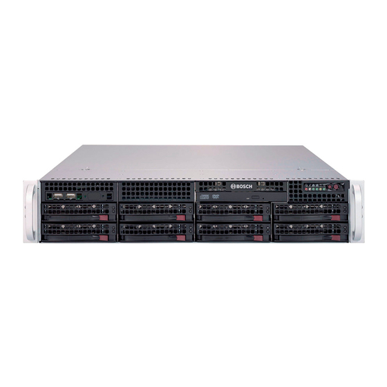
Running the full Bosch VMS (Video Management System) solution and powered by Bosch VRM (Video Recording Manager) software, the DIVAR IP 7000 is an intelligent IP storage device that eliminates the need for separate NVR (Network Video Recorder) server and storage hardware. -
Page 10: Chassis
System interface There are several LEDs on the front and rear of the chassis. The LEDs show the over-all status of the system and the activity and health of specific components. 2014.12 | V4 | DOC Installation Manual Bosch Sicherheitssysteme GmbH... -
Page 11: Control Panel Buttons
Control panel buttons There are two push-buttons located on the front of the chassis. These are (in order from left to right) a reset button and a power on/off button. Bosch Sicherheitssysteme GmbH Installation Manual 2014.12 | V4 | DOC... -
Page 12: Control Panel Leds
Power: Indicates power is being supplied to the system's power supply units. This LED should normally be illuminated when the system is operating. 2.3.3 Drive carrier LEDs Your chassis uses SAS/SATA. SAS/SATA drives Each SAS/SATA drive carrier has two LEDs. 2014.12 | V4 | DOC Installation Manual Bosch Sicherheitssysteme GmbH... - Page 13 LED to blink on and off when that particular drive is being accessed. – Red: The red LED indicates a SAS/SATA drive failure. If one of the SAS/SATA drives fail, you should be notified by your system management software. Bosch Sicherheitssysteme GmbH Installation Manual 2014.12 | V4 | DOC...
-
Page 14: Chassis Setup And Maintenance
Except for short periods of time, do NOT operate the server without the cover in place. The chassis cover must be in place to allow proper airflow and prevent overheating. 2014.12 | V4 | DOC Installation Manual Bosch Sicherheitssysteme GmbH... -
Page 15: Installing Hard Drives
Use the handle to pull the drive out of the chassis. Notice! Except for short periods of time (swapping hard drives), do not operate the unit with the hard drives removed from the bays. Bosch Sicherheitssysteme GmbH Installation Manual 2014.12 | V4 | DOC... -
Page 16: Installing A Hard Drive
Secure the hard drive by tightening all 6 screws. Drive carrier SAS/SATA hard drive Replace the drive carrier into the chassis bay. Make sure that the drive carrier handle is completely closed. 2014.12 | V4 | DOC Installation Manual Bosch Sicherheitssysteme GmbH... -
Page 17: Installing A Fixed Hard Drive
Chassis setup and maintenance | en Notice! We recommend using the respective Bosch hard disk drives. The hard disk drives as one of the critical component are carefully selected by Bosch based on available failure rates. HDD – not delivered from Bosch – are not supported. Information on supported HDDs can be found in the datasheet in the Bosch Online Product Catalog. -
Page 18: Replacing Or Installing A Dvd-Rw
The chassis model includes an internal USB transcoder device. Notice! To replace or install the transcoder device, please apply to one of the Bosch RMA helpdesks. Replacing or installing the front port panel The chassis model includes a front port panel. -
Page 19: Installing The Motherboard
Motherboard problems will be handled by trained support people only. Installing the air shroud Air shrouds concentrate airflow to maximize fan efficiency. The air shroud does not require screws to set up. Bosch Sicherheitssysteme GmbH Installation Manual 2014.12 | V4 | DOC... -
Page 20: Checking The Air Flow
Rack installation, page 24. 3.10 Replacing the system fans The system fans provide cooling for the chassis. These fans circulate air through the chassis as a means of lowering the chassis internal temperature. 2014.12 | V4 | DOC Installation Manual Bosch Sicherheitssysteme GmbH... -
Page 21: Power Supply
The chassis has two redundant power supplies. The power supplies are auto-switching capable. This enables the power supplies to automatically sense and operate at a 100 V to 240 V input voltage. Bosch Sicherheitssysteme GmbH Installation Manual 2014.12 | V4 | DOC... -
Page 22: Replacing The Power Supply
Replacing the power supply The power supply can be replaced without turning off the system if a redundant power supply is available. Replacement units can be ordered directly from Bosch RMA desk. To replace the power supply: Only for units with one power supply: Turn off the unit and unplug the power cord. -
Page 23: Replacing The Power Distributor
Slide the new power distributor module into the power distributor housing. Make that you slide the cables through the bottom of the housing. Reconnect all the power cables, replace the power supply, and insert the plug into the wall. Bosch Sicherheitssysteme GmbH Installation Manual 2014.12 | V4 | DOC... -
Page 24: Rack Installation
You should inspect the box the chassis was shipped in and note if it was damaged in any way. If the chassis itself shows damage, file a damage claim with the carrier who delivered it and notify the respective Bosch RMA desk. You will also need it placed near at least one grounded power outlet. -
Page 25: General System Precautions
You should also refer to the installation instructions that came with the rack unit you are using. Bosch Sicherheitssysteme GmbH Installation Manual 2014.12 | V4 | DOC... -
Page 26: Separating The Sections Of The Rack Rails
Locate the rail assembly in the chassis packaging. Extend the rail assembly by pulling it outward. Press the quick-release tab. Separate the inner rail extension from the outer rail assembly. 2014.12 | V4 | DOC Installation Manual Bosch Sicherheitssysteme GmbH... -
Page 27: Installing The Inner Rails
Hang the hooks of the rails onto the rack holes and if desired, use screws to secure the front of the outer rail onto the rack. Repeat steps 1-3 for the remaining outer rail. Bosch Sicherheitssysteme GmbH Installation Manual 2014.12 | V4 | DOC... -
Page 28: Installing The Chassis Into The Rack
Larger chassis should be positioned to balance the weight between front and back. If a bezel is included on the chassis, remove it. Then attach the two front brackets to each side of 2014.12 | V4 | DOC Installation Manual Bosch Sicherheitssysteme GmbH... -
Page 29: Turning On The System
Plug the power cord from the power supply unit into a high-quality power strip that offers protection from electrical noise and power surges. We recommended using an uninterruptible power supply (UPS). Press the power button on the control panel to turn on the system. Bosch Sicherheitssysteme GmbH Installation Manual 2014.12 | V4 | DOC... -
Page 30: System Setup - First Steps
The Microsoft Software License Terms and the EULA (End User License Agreement) are displayed. Accept the license terms, then click Start. Windows restarts. After restart is finished, different Bosch VMS versions are displayed on the screen. 2014.12 | V4 | DOC Installation Manual... -
Page 31: Using Bosch Vms Config Wizard
Note: In case of password loss a system recovery must be performed as described in the installation manual. The configuration must be done from scratch or must be imported. 11. On the Bosch VMS default screen, double-click the Bosch VMS Wizard icon to start the Configuration Wizard. -
Page 32: Adding Additional Licenses
On a computer with Internet access, enter the following URL into your browser: https://activation.boschsecurity.com If you do not have an account to access the Bosch License Activation Center, either create a new account (recommended) or click the link to activate a new license without logging on. - Page 33 Cameras in the Logical Tree with a red dot in the camera’s icon are recording. To verify playback functionality in the Operator Client The time line moves if the a camera is viewed in playback mode. To perform further functionalities refer to the Bosch VMS manual. Performance overview live 4CIF 2.5 Mbit...
-
Page 34: Connecting To The Internet
To set up port forwarding: Make sure the system is fully configured with all devices. On the Bosch VMS default screen, double-click the Bosch VMS Wizard icon. The Welcome page is displayed. Follow the wizard until the Basic page is displayed. -
Page 35: Installing An Enterprise Management Server
User name: admin Password: enter user password Notice! Only use Bosch VMS Operator Client Video Security App in the version that matches DIVAR IP. Other clients or application software may work but are not supported. Installing an Enterprise Management Server For a central management of multiple systems you can install Bosch VMS Enterprise Management Server on a separate server. -
Page 36: Recovering The Unit
"write through" if no UPS is active, and the controller be buffered by a battery, when controller cache is set to "write back". Nevertheless, both caches have a great influence on the RAID performance. 2014.12 | V4 | DOC Installation Manual Bosch Sicherheitssysteme GmbH... - Page 37 RAID configuration. "New" or "Clear" Configuration deletes the COD, if available. "Save Configuration" saves the new COD. "Initialize" deletes the Disk Data (OS). Bosch Sicherheitssysteme GmbH Installation Manual 2014.12 | V4 | DOC...
-
Page 38: Multiple Disks Failed - Theory
But the "second failed" disk must be used for hopefully get the offline RAID degraded again. Two tools are useful to analyze what happened: - the Event Viewer in the Controller Bios Utility - the MegaCLI, a Command-Line Utility 2014.12 | V4 | DOC Installation Manual Bosch Sicherheitssysteme GmbH... - Page 39 In this example, we choose a start sequence 5800 (from 6412) and all 612 events left. We find a timestamp, that PD (Physical Drive) 6 was removed. PD 4 stops rebuilding. Finally, PD 4 is also removed. Bosch Sicherheitssysteme GmbH Installation Manual 2014.12 | V4 | DOC...
- Page 40 Event Description: Patrol Read can't be started, as PDs are either not ONLINE, or are in a VD with an active process, or are in an excluded VD Event Data: 2014.12 | V4 | DOC Installation Manual Bosch Sicherheitssysteme GmbH...
- Page 41 Event Description: VD 00/0 is now DEGRADED Event Data: =========== Target Id: 0 seqNum: 0x000018bc Time: Mon Jul 19 14:12:25 2010 Code: 0x000000fb Class: 2 Locale: 0x01 Event Description: VD 01/1 is now DEGRADED Bosch Sicherheitssysteme GmbH Installation Manual 2014.12 | V4 | DOC...
-
Page 42: Multiple Disks Failed - Practice
Target Id: 0 Target Id: 1 7.2.2 Multiple disks failed – practice Press "C" to enter Utility. Click "start" and "scan disks". You get to the "foreign configuration import" screen. 2014.12 | V4 | DOC Installation Manual Bosch Sicherheitssysteme GmbH... - Page 43 All disks are seen, but configuration is marked as not importable; click Cancel and view Configuration 2. It is the same; this means, a complex situation requires manual interaction. Click to clear all configurations, ignore the warning. Bosch Sicherheitssysteme GmbH Installation Manual 2014.12 | V4 | DOC...
- Page 44 In this example, disk in Slot 4 was first fail, Slot 7 second fail. Click on "second fail" PD7 in the Logical View and you get in the Physical drive menu. Choose "replace missing PD" and the correct row for Slot 7 drive and click "go". Ignore the warning. 2014.12 | V4 | DOC Installation Manual Bosch Sicherheitssysteme GmbH...
- Page 45 Now in logical view we see disk online and a degraded RAID. Click on disk 4 to get in the PD menu. Click on correct row, on "Global" or "dedicated Hot Spare" and on "go". Click on home; in the Logical View, the rebuild is starting. Bosch Sicherheitssysteme GmbH Installation Manual 2014.12 | V4 | DOC...
-
Page 46: Foreign Configuration Disk Appears In The Windows Gui After Booting
GUI. Click "scan foreign configuration". In the next window, click "clear foreign configuration". An unconfigured good drive is displayed. Right-click this drive and choose a hotspare type. You see the rebuild is starting at once. 2014.12 | V4 | DOC Installation Manual Bosch Sicherheitssysteme GmbH... -
Page 47: Megacli Commandline Utility
MegaCli -AdpSetProp -CopyBackDsbl -val -aN|-a0,1,2|-aALL val - 0=Enable Copyback. 1=Disable Copyback. MegaCli -AdpSetProp -EnableJBOD -val -aN|-a0,1,2|-aALL val - 0=Disable JBOD mode. 1=Enable JBOD mode. MegaCli -AdpSetProp -DsblCacheBypass -val -aN|-a0,1,2|-aALL val - 0=Enable Cache Bypass. Bosch Sicherheitssysteme GmbH Installation Manual 2014.12 | V4 | DOC... - Page 48 MegaCli -AdpDiag [val] -aN|-a0,1,2|-aALL val - Time in second. MegaCli -AdpBatTest -aN|-a0,1,2|-aALL MegaCli -PDList -aN|-a0,1,2|-aALL MegaCli -PDGetNum -aN|-a0,1,2|-aALL MegaCli -pdInfo -PhysDrv[E0:S0,E1:S1,...] -aN|-a0,1,2|-aALL MegaCli -PDOnline -PhysDrv[E0:S0,E1:S1,...] -aN|-a0,1,2|-aALL MegaCli -PDOffline -PhysDrv[E0:S0,E1:S1,...] -aN|-a0,1,2|-aALL 2014.12 | V4 | DOC Installation Manual Bosch Sicherheitssysteme GmbH...
- Page 49 MegaCli -CfgLdDel -LX|-L0,2,5...|-LALL -aN|-a0,1,2|-aALL MegaCli -CfgSscdDel -LX|-L0,2,5...|-LALL -aN|-a0,1,2|-aALL MegaCli -CfgFreeSpaceinfo -aN|-a0,1,2|-aALL MegaCli -CfgSpanAdd -r10 -Array0[E0:S0,E1:S1] -Array1[E0:S0,E1:S1] [- ArrayX[E0:S0,E1:S1] ...] -aN MegaCli -CfgSpanAdd -r50 -Array0[E0:S0,E1:S1,E2:S2,...] -Array1[E0:S0,E1:S1,E2:S2,...] [-ArrayX[E0:S0,E1:S1,E2:S2,...] ...] [WT|WB] [NORA|RA|ADRA] [Direct|Cached] Bosch Sicherheitssysteme GmbH Installation Manual 2014.12 | V4 | DOC...
- Page 50 MegaCli -EnclFwDownload -Encl N -Esm A|B -f <filename> -aN|-a0,1,2|-aALL MegaCli -PdFwDownload [-SataBridge] -PhysDrv[0:1,1:2,...] -f <filename> -aN|-a0,1,2|-aALL MegaCli -SetFacDefault -Encl N -Esm A|B -f <filename> -aN|-a0,1,2|-aALL MegaCli -PDCpyBk -Start -PhysDrv[E0:S0,E1:S1] -aN|-a0,1,2|-aALL 2014.12 | V4 | DOC Installation Manual Bosch Sicherheitssysteme GmbH...
- Page 51 The following options may be given at the end of any command above: [-Silent] [-AppLogFile filename] [-NoLog] [-page [N]] [-] is optional. N - Number of lines per page. Exit Code: 0x00 Bosch Sicherheitssysteme GmbH Installation Manual 2014.12 | V4 | DOC...
-
Page 52: Additional Documentation And Client Software
DIVAR IP 7000 2U Additional documentation and client software Documentation for Bosch Security Systems products can be found as follows: Open any browser > enter www.boschsecurity.com > select your region and your country > start a search for your product > select the product in the search results to show the existing documents. -
Page 53: Appendices
– All systems have a SATA DOM connected to Serial ATA ports (I-SATA-5) with a small power connector (DOM PWR). – SATA-DOM: Is plugged in connector I-SATA-5 on the motherboard. Bosch Sicherheitssysteme GmbH Installation Manual 2014.12 | V4 | DOC... -
Page 54: Motherboard Component Overview
JI2C1/JI2C2 SMB to PCI Slots JPG1 Onboard VGA Enable Pins 1-2 (Enabled) 11,12 JPL1/JPL2 LAN1/LAN2 Enable Pins 1-2 (Enabled) JPT1 TPM Enable Pins 1-2 (Enabled) BMC Jumper Pins 1-2 (Enabled) 2014.12 | V4 | DOC Installation Manual Bosch Sicherheitssysteme GmbH... - Page 55 Trusted Platform Module (TPM) Header Onboard Video Port X8SIL/X8SIL-F/X8SIL-V LED indicators Number Description Color/State Status Onboard Standby PWR LED Green: Solid on PWR On Indicator IPMI Heartbeat LED (X8SIL-F Yellow: Blinking IPMI: Normal Only) Bosch Sicherheitssysteme GmbH Installation Manual 2014.12 | V4 | DOC...
-
Page 56: Motherboard Features
One (1) floppy drive interface (up to 1.44 MB) USB Devices (X8SIL Only) Two (2) USB ports on the rear IO panel One (1) Type A internal connector I/O Devices (Continued) USB Devices (X8SIL-F/X8SIL-V Only) 2014.12 | V4 | DOC Installation Manual Bosch Sicherheitssysteme GmbH... - Page 57 PECI (Platform Environment Configuration Interface) 2.0 support System resource alert via Supero Doctor III SuperoDoctor III, Watch Dog, NMI Chassis Intrusion Header and Detection CD Utilities BIOS flash upgrade utility Bosch Sicherheitssysteme GmbH Installation Manual 2014.12 | V4 | DOC...
-
Page 58: Block Diagram
F/X8SIL-V motherboard to offer a high-speed Direct Media Interface (DMI) for chip-to-chip true isochronous communication with the processor. This feature allows the X8SIL/X8SIL-F/X8SIL- V to achieve up to 10 Gb/s of software-transparent data transfer on each direction, achieving 2014.12 | V4 | DOC Installation Manual Bosch Sicherheitssysteme GmbH... -
Page 59: Pc Health Monitoring
Pressing the power button again to wake-up the whole system. During the SoftOff state, the ATX power supply provides power Bosch Sicherheitssysteme GmbH Installation Manual 2014.12 | V4 | DOC... -
Page 60: Power Supply
Unlike fiber-optic networks that require special cabling, iSCSI can run over long distance using existing networks. 2014.12 | V4 | DOC Installation Manual Bosch Sicherheitssysteme GmbH... -
Page 61: Overview Of The Nuvoton Bmc Controller
WPCM450 (Manufacturer P/N WPCM450RA0BX) also has all the features as described above plus IPMI 2.0 support. This particular chip is installed in the X8SIL-F and X8SIL-V models. However, IPMI is supported only on the X8SIL-F motherboard. Bosch Sicherheitssysteme GmbH Installation Manual 2014.12 | V4 | DOC... - Page 64 Bosch Sicherheitssysteme GmbH Robert-Bosch-Ring 5 85630 Grasbrunn Germany www.boschsecurity.com © Bosch Sicherheitssysteme GmbH, 2014...