Table of Contents
Advertisement
Quick Links
Use & Care Guide
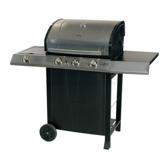
Liquid Propane Gas Grill
Sears Model No. 415.16114010
Safety
•
Parts
•
Use and Care
•
Assembly
•
This Grill is for Outdoor Use Only
WARNING
•
Read and follow all Safety, Assembly,
and Use & Care Instructions in this
Guide before assembling and cooking
with this grill.
•
Failure to follow all instruc tions in this
Use & Care Guide may lead to fire or
explosion, which could result in property
damage, personal injury or death.
Sears Brands Management Corporation, Hoffman Estates, IL 60179 U.S.A.
©2010 Sears Brands, LLC
®
See our extensive assortment of outdoor living products on-line at
www.sears.com and www.kmart.com
Grill Information Center
Missing Parts? Assembly Questions?
Operation Problems? Before returning
grill to store, call 1-800-241-7548
Tools needed for assembly:
Adjustable wrench (not provided)
Screwdriver (not provided)
7/16" Combination wrench (not provided)
Printed in China
G451-001-030801 • Nov-26-09
Model 464323510
Advertisement
Table of Contents

Related Manuals for Kenmore 415.16114010


Summary of Contents for Kenmore 415.16114010
- Page 1 Use & Care Guide ® Liquid Propane Gas Grill Sears Model No. 415.16114010 Safety • Parts • Use and Care • Assembly • This Grill is for Outdoor Use Only Grill Information Center Missing Parts? Assembly Questions? Operation Problems? Before returning...
-
Page 2: For Your Safety
DANGER WARNING CALIFORNIA PROPOSITION 65 If you smell gas: 1. Combustion by-products produced when using 1. Shut off gas to the appliance. this product contain chemicals known to the State of 2. Extinguish any open flame. California to cause cancer, birth defects, and other 3. -
Page 3: Table Of Contents
Kenmore Grill Warranty ....... 3 Use and Care ........4-10 Five-Year Limited Warranty on Burners Parts List . -
Page 4: Use And Care
LP Tank USE AND CARE • The LP Tank used with your grill must meet the following requirements: DANGER • Use LP Tanks only with these required measurements: 12" (30.5cm) (diameter) x 18" (45.7 cm) (tall) with 20 lb. (9 kg.) capacity maximum. - Page 5 LP Tank Exchange Connecting Regulator To The LP Tank • Many retailers that sell grills offer you the option of replacing 1. LP tank must be properly secured onto grill. (Refer to your empty LP tank through an exchange service. Use only assembly section.) those reputable exchange companies that inspect, precision fill, 2.
- Page 6 Leak Testing Valves, Hose and Regulator 1. Turn all grill control knobs to OFF. 2. Be sure regulator is tightly connected to LP tank. 3. Completely open LP tank valve by turning OPD hand wheel counterclockwise. If you hear a rushing sound, turn gas off immediately.
- Page 7 Safety Tips WARNING Before opening LP cylinder valve, check the coupling nut for tightness. When grill is not in use, turn off all control knobs and LP cylinder valve. For Safe Use of Your Grill and to Avoid Serious Never move grill while in operation or still hot. Injury: Use long-handled barbecue utensils and oven mitts to avoid •...
- Page 8 Burner Flame Check WARNING • Remove cooking grates and flame tamers. Light burners, rotate knobs from HI to LOW. You should see a smaller flame in LOW position than seen on HI. Perform burner flame check Turn controls and gas source or tank OFF when not on sideburner, also.
- Page 9 3. Remove carryover tubes and burners. CAUTION Detach electrode from burner. NOTE: Removal/Detachment method will depend on the burner configuration. See different configurations in SPIDER ALERT! illustrations below. 5. Carefully lift each burner up and away from valve openings. We suggest three ways to clean the burner tubes. Use the one SPIDER AND WEBS easiest for you.
- Page 10 Indirect Cooking Food Safety Poultry and large cuts of meat cook slowly to perfection on the Food safety is a very important part of enjoying the outdoor grill by indirect heat. Place food over unlit burner(s); the heat cooking experience. To keep food safe from harmful bacteria, from lit burners circulates gently throughout the grill, cooking follow these four basic steps: meat or poultry without the touch of a direct flame.
-
Page 11: Parts List
PARTS LIST Key Qty Description Part Number Key Qty Description Part Number 1 LEFT LEG ASSEMBLY G430-1000-W1 1 SWING AWAY GRATE G431-0032-W1 1 MATCH HOLDER G401-0079-W1 1 BUTTON, F/ EI MODULE G501-0072-W1 1 RIGHT LEG ASSEMBLY G430-4800-W1 1 CLIP, F/ GREASE CUP G305-0043-W1 1 BOTTOM SHELF G430-1100-W1... -
Page 12: Parts Diagram
PARTS DIAGRAM 12 • 464323510... -
Page 13: Assembly
CAUTION: When unpacking grill components, two people should raise grill head from the shipping box. Bottom Shelf to Legs Place bottom shelf end with cut out hole for LP cylinder between legs with axle holes. Attach to right and left leg assemblies with (4)1/4-20x1-1/2"... - Page 14 Wheels and Leg Extenders to Cart Turn assembly upside down. Insert axle rod through wheel, wheel spacer, legs, wheel spacer and other wheel. Be sure to face “cone” side of wheel against leg. Attach with (1) Axle washer and hitch pin. Hammer leg extenders into right legs.
- Page 15 Front Panels Stand cart upright. Attach back brace to top of cart with (4) #8x3/8" self-tap screws. Attach lower front panel ( with pin) to lower half of cart with (4) #8x3/8" self-tap screws. Attach upper front panel (without pin) to upper half of cart with (4) #8x3/8” self-tap screws. Back Brace #8x3/8"...
- Page 16 Grill Head to Cart Stand cart upright. This step requires two people to lift and position grill head onto cart. Carefully lower the grill head onto the cart. Make sure the regulator hose is hanging outside the cart. Attach with (4) 1/4-20x1/2"...
- Page 17 Right Side Shelf Hook side wall of shelf over support brackets on side of firebox (A). Insert (2) 7mm fiber washers and (2) 1/4-20x1/2" screws through inside front of firebox and through outside back of firebox for each side as shown (B). Attach shelf with (4) 1/4-20 flange nuts (C).
- Page 18 Side Burner Shelf Hook side wall of side burner shelf over support brackets on side of firebox (A). Inside firebox insert (4) fiber washers (4) 1/4-20x1/2" screws as shown (B). Attach shelf using (4) 1/4-20 flange nuts on each side (C). 1/4-20x1/2"...
- Page 19 Sideburner Valve, Sideburner, Sideburner Bezel, Ignitor Wire, Control Knob Position valve behind fascia and line up holes (A). Insert (1) of the #8-32x3/8” stainless steel screws, do not fully tighten. Slip bezel under inserted screw and position as shown (A). Line up other hole and insert (1) #8-32x3/8”...
- Page 20 Heat Shield Attach heat shield over burners inside front of grill with (2) #8-32x3/8’’ sheet metal screws Lid removed for clarity Heat Shield #8x3/8" self-tap screws Qty.2 Grill Front Grill Back 20 • 464323510...
- Page 21 Heat Diffusers Place heat diffusers over burners by inserting tabs into slots in front of firebox. Opposite ends of heat diffusers rest on pins in back of firebox. Cooking Grate and Swing Away Place cooking grates onto grate rests. Insert ends of Swing Away pivot wire into holes in sides of grill lid. Insert ends of Swing Away leg wire into holes in sides of firebox. NOTE: Pivot and leg wires, running side-to-side, should be under wires running front-to-back.
- Page 22 Grease Cup Clip and Grease Cup Hang grease cup clip from bottom of firebox and place grease cup into grease cup clip. CAUTION Failure to install grease cup clip and cup will cause hot grease to drip from bottom of grill with risk of fire or property damage. Grease Cup Clip Grease Cup LP Tank...
-
Page 23: Troubleshooting
EMERGENCIES: If a gas leak cannot be stopped, or a fire occurs due to gas leakage, call the fire department. Emergencies Possible Cause Prevention/Solution Gas leaking from • Damaged hose. • Turn off gas at LP cylinder or at source on natural gas systems. If the cracked/cut/burned hose is cracked or cut but not burned, simply replace valve/hose/ hose. - Page 24 Troubleshooting (continued) Problem Possible Cause Prevention/Solution Burner(s) will not light ELECTRONIC IGNITION: using ignitor. • No spark, no ignition noise. • See Section I of Electronic Ignition System. (See Electronic Ignition Troubleshooting also) • No spark, some ignition noise. • See Section II of Electronic Ignition System. •...
- Page 25 Troubleshooting - Electronic Ignition Problem (Ignition) Possible Cause Check Procedure Prevention/Solution SECTION I No sparks appear at • Battery not installed • Check battery orientation. • Install battery (make sure that “+” and “–” any electrodes when properly. connectors are oriented correctly, with “+” end up Electronic Ignition Button and “–”...
- Page 26 NOTES 26 • 464323510...
- Page 27 NOTES 464323510 • 27...
- Page 28 Get it fixed, at your home or ours! Your Home For expert troubleshooting and home solutions advice: www.managemyhome.com For repair – in your home – of all major brand appliances, lawn and garden equipment, or heating and cooling systems, no matter who made it, no matter who sold it! For the replacement parts, accessories and owner’s manuals that you need to do-it-yourself.