
Related Manuals for Yamaha YZ450FX 2019


Summary of Contents for Yamaha YZ450FX 2019
- Page 1 2019 OWNER’S SERVICE MANUAL YZ450FX Read this manual carefully before operating this vehicle. YZ450FXK ■ LIT-11626-32-25 B3J-28199-10...
- Page 2 EAM20161 Read this manual carefully Operating, servicing and maintaining a passenger vehicle or off-road vehicle can expose you to chemicals including engine exhaust, carbon monoxide, phthalates, and lead, which are known to the State of California to cause cancer and birth defects or other reproductive harm.
- Page 3 EAM20161 Read this manual carefully before operating this vehicle. This manual should stay with this vehicle if it is sold. FCC CAUTION Changes or modifications not expressly approved by the party responsible for compliance could void the user’s authority to operate the equipment. This transmitter must not be co-located or operated in conjunction with any other antenna or transmitter.
- Page 4 EAM20080 YZ450FXK OWNER’S SERVICE MANUAL ©2019 by Yamaha Motor Corporation, U.S.A. First edition, May 2018 All rights reserved. Any reprinting or unauthorized use without the written permission of Yamaha Motor Corporation, U.S.A. is expressly prohibited. Printed in Japan. P/N. LIT-11626-32-25...
- Page 5 EAM20081 INTRODUCTION Congratulations on your purchase of a Yamaha YZ series. This model is the culmination of Yamaha’s vast experience in the production of pacesetting racing machines. It represents the highest grade of craftsmanship and reliability that have made Yamaha a leader.
- Page 6 EAM20092 SAFETY INFORMATION THIS MACHINE IS DESIGNED STRICTLY FOR COMPETITION USE, ONLY ON A CLOSED COURSE. It is illegal for this machine to be operated on any public street, road, or highway. Off-road use on public lands may also be illegal. Please check local regulations before riding. •...
- Page 7 EAM20162 YAMAHA MOTOR CORPORATION, U.S.A. YZ MOTORCYCLE LIMITED WARRANTY...
- Page 8 EAM20082 HOW TO USE THIS MANUAL In this manual, descriptions of installation, removal, disassembly, assembly, check, and adjustment procedures are laid out with the individual steps in sequential order. • The manual is divided into chapters and each chapter is divided into sections. The current section title “1”...
- Page 9 EAM20083 SYMBOLS The following symbols are used in this manual for easier understanding. The following symbols are not relevant to every vehicle. SYMBOL DEFINITION SYMBOL DEFINITION Serviceable with engine mounted Gear oil Filling fluid Molybdenum disulfide oil Lubricant Brake fluid Special tool Wheel bearing grease Tightening torque...
-
Page 11: Table Of Contents
TABLE OF CONTENTS EAM10003 GENERAL INFORMATION SPECIFICATIONS PERIODIC CHECKS AND ADJUSTMENTS CHASSIS ENGINE COOLING SYSTEM FUEL SYSTEM ELECTRICAL SYSTEM TROUBLESHOOTING TUNING... - Page 13 GENERAL INFORMATION LOCATION OF IMPORTANT LABELS.............1-1 DESCRIPTION....................1-2 IDENTIFICATION ....................1-3 VEHICLE IDENTIFICATION NUMBER ............1-3 ENGINE SERIAL NUMBER................1-3 INCLUDED PARTS ...................1-4 NIPPLE WRENCH ..................1-4 HANDLEBAR PROTECTOR ..............1-4 FUEL HOSE JOINT COVER ..............1-4 POWER TUNER ..................1-4 IMPORTANT INFORMATION ................1-6 PREPARATION FOR REMOVAL AND DISASSEMBLY ......1-6 REPLACEMENT PARTS ................1-6 GASKETS, OIL SEALS AND O-RINGS .............1-7 LOCK WASHERS/PLATES AND COTTER PINS ........1-7...
- Page 14 BREAK-IN PROCEDURES ..............1-22 ENGINE STARTING PRECAUTION ............1-22 MAINTENANCE AFTER BREAK-IN ..............1-23 MAJOR MAINTENANCE ................1-23 TORQUE-CHECK POINTS................1-24 MOTORCYCLE CARE AND STORAGE............1-26 CARE ......................1-26 STORAGE ....................1-27...
-
Page 15: Location Of Important Labels
LOCATION OF IMPORTANT LABELS EAM20085 LOCATION OF IMPORTANT LABELS Please read the following important labels carefully before operating this vehicle. Premium unleaded gasoline only. 3FB-2415E-02 WARNING This unit contains high pressure nitrogen gas. Mishandling can cause explosion. Read owner's manual for instructions. Do not incinerate, puncture or open. -
Page 16: Description
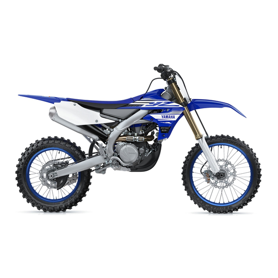
DESCRIPTION EAM20086 DESCRIPTION 2, 3 11.Fuel tank 1. Clutch lever 12.Radiator 2. Engine trouble warning light “ ” 13.Coolant drain bolt 3. Fuel level warning light “ ” 14.Rear brake pedal 4. Front brake lever 15.Air filter 5. Throttle grip 16.Drive chain 6. -
Page 17: Identification
There are two significant reasons for knowing the serial number of your vehicle: 1. When ordering parts, you can give the num- ber to your Yamaha dealer for positive identi- fication of the model you own. 2. If your vehicle is stolen, the authorities will need the number to search for and identify your vehicle. -
Page 18: Included Parts
INCLUDED PARTS EAM20088 EWA20460 INCLUDED PARTS WARNING • Do not operate the engine in a closed area. EAM30005 The exhaust gas is poisonous. NIPPLE WRENCH • Never let flames near the servicing area. The nipple wrench “1” is used to tighten the spoke. - Page 19 INCLUDED PARTS pressed or while the engine is running (the CCU is activated), input the CCU serial num- ber into your smartphone and establish a wireless connection. 3. Activate the Power Tuner app. If the CCU wireless network cannot be detected, operate the start switch again.
-
Page 20: Important Information
Make sure that the parts and grease or oil to be used for repair of the vehicle, including periodic 2. Use proper special tools and equipment. Re- replacement parts, are new YAMAHA genuine fer to “SPECIAL TOOLS” on page 1-12. parts and recommended parts. -
Page 21: Gaskets, Oil Seals And O-Rings
IMPORTANT INFORMATION EAM30011 GASKETS, OIL SEALS AND O-RINGS 1. When overhauling the engine, replace all gaskets and O-rings. All gasket surfaces, oil seal lips, and O-rings must be cleaned so that there may be no dust on them. 2. During assembly, always apply proper oil to bearings and proper grease to oil seal lips be- fore installation. -
Page 22: Basic Service Information
BASIC SERVICE INFORMATION EAM20120 BASIC SERVICE INFORMATION EAM30181 ELECTRICAL SYSTEM Electrical parts handling ECA16600 NOTICE Never disconnect a battery lead while the en- gine is running; otherwise, the electrical components could be damaged. ECA16760 NOTICE Be sure to connect the battery leads to the correct battery terminals. - Page 23 BASIC SERVICE INFORMATION ECA16630 ECA14371 NOTICE NOTICE Electrical components are very sensitive to Never insert the tester probes into the cou- and can be damaged by static electricity. pler terminal slots. Always insert the probes Therefore, never touch the terminals and be from the opposite end “a”...
- Page 24 BASIC SERVICE INFORMATION ECA16780 NOTICE • When disconnecting a coupler, release the coupler lock, hold both sections of the cou- pler securely, and then disconnect the cou- pler. • There are many types of coupler locks; therefore, be sure to check the type of cou- pler lock before disconnecting the coupler.
- Page 25 BASIC SERVICE INFORMATION 5. Check: • No continuity Digital circuit tester (CD732) 90890-03243 Model 88 Multimeter with tachom- eter YU-A1927 • If there is no continuity, clean the terminals. • When checking the wire harness, perform steps (1) to (4). •...
-
Page 26: Special Tools
3-7, 3-8 90890-01325 Mityvac cooling system tester kit YU-24460-A YU-24460-A Radiator cap tester adapter 3-7, 3-8 90890-01352 Pressure tester adapter YU-33984 YU-33984 Yamaha diagnostic tool USB (US) 3-15, 7-9, 8-25 90890-03257 Yamaha diagnostic tool (A/I) 3-15, 7-9, 8-25 90890-03262 1-12... - Page 27 SPECIAL TOOLS Reference Tool name/Tool No. Illustration pages FI diagnostic tool sub–lead 3-15, 7-9, 8-26 90890-03212 FI diagnostic tool sub–lead YU-03212 OBD/ GST Leadwire kit 3-15, 7-9, 8-25 90890-03249 Digital tachometer 3-16, 3-37, 8-65 90890-06760 Digital tachometer YU-39951-B Thickness gauge 3-17, 5-43 90890-03268 Feeler gauge set...
- Page 28 4-41, 4-44 90890-01500 Cap bolt wrench YM-01500 Fork seal driver 4-45, 4-46 90890-01502 Fork seal driver (48) YM-A0948 Yamaha bond No. 1215 5-18, 5-58, 5-65 90890-85505 (Three bond No.1215®) Valve spring compressor 5-25, 5-30 90890-04019 Valve spring compressor YM-04019 Valve spring compressor attachment...
- Page 29 SPECIAL TOOLS Reference Tool name/Tool No. Illustration pages Valve guide installer (ø5.5) 5-27 90890-04015 Valve guide installer (5.5 mm) YM-04015 Valve guide reamer (5.5 mm) 5-27 90890-01196 Valve guide reamer (5.5 mm) YM-01196 Piston pin puller set 5-32 90890-01304 Piston pin puller YU-01304 YU-01304 Universal clutch holder...
- Page 30 SPECIAL TOOLS Reference Tool name/Tool No. Illustration pages Crankcase separating tool 5-68 90890-04152 Crankcase separating tool YU-A9642 Crankshaft installer pot 5-69 90890-01274 Installing pot YU-90058 YU-90058/YU-90059 Crankshaft installer bolt 5-69 90890-01275 Bolt YU-90060 Adapter (M12) 5-69 90890-01278 Adapter #3 YU-90063 Spacer (crankshaft installer) 5-69 90890-04081...
- Page 31 SPECIAL TOOLS Reference Tool name/Tool No. Illustration pages Pressure gauge 90890-03153 Pressure gauge YU-03153 Fuel pressure adapter 90890-03186 Fuel pressure adapter YM-03186 Lithium battery charger 8-60, 8-60 90890-05376 Lithium battery charger DBY-ACC51-70-02 Ignition checker 8-62 90890-06754 Oppama pet–4000 spark checker YM-34487 Test harness S–...
-
Page 32: Control Functions
” This warning light comes on or flashes if a prob- lem is detected in the electrical circuit monitoring the engine. If this occurs, have a Yamaha dealer check the vehicle. The electrical circuit of the warning light can be checked by pushing the start switch. -
Page 33: Clutch Lever
CONTROL FUNCTIONS EAM30187 THROTTLE GRIP You can use the Power Tuner app to adjust the The throttle grip “1” is located on the right han- map settings. dlebar. The throttle grip accelerates or deceler- When the mode switch “1” is illuminated, map 2 ates the engine. -
Page 34: Starter Knob
CONTROL FUNCTIONS • Install the fuel tank cap cover after placing the EWA18980 WARNING bands “3” all the way in under the seat. • Never apply additional force to the sides- tand. • Hold up the sidestand before starting out. a a a EAM30444 STARTER KNOB... -
Page 35: Starting And Break-In
EMENT” section in the CHAPTER 3, apply the ents, do not start or warm it up at an illventi- Yamaha foam air filter oil or other quality foam lated place or a closed narrow place. air filter oil to the element. (Excess oil in the ele- ment may adversely affect engine starting.) -
Page 36: Starting A Warm Engine
STARTING AND BREAK-IN 5. To stop the engine, push the engine stop drive chain, looseness of the spoke, and so switch “1”. ECA25821 NOTICE Continue pushing the engine stop switch till the After a break-in or after each race, always engine comes to a full stop. -
Page 37: Maintenance After Break-In
MAINTENANCE AFTER BREAK-IN Lubricate the drive chain and adjust its ten- EAM20124 MAINTENANCE AFTER BREAK-IN sion. After a break-in, perform careful maintenance to • Fuel tank get ready for the next practice or race. Clean the inside of the fuel tank. Check for Refer to “PRE-OPERATION INSPECTION AND leaks. -
Page 38: Torque-Check Points
TORQUE-CHECK POINTS EAM20125 TORQUE-CHECK POINTS Frame construction Frame to rear frame Frame to engine protector Combined seat and fuel tank Fuel tank to frame Engine mounting Frame to engine Engine bracket to engine Engine bracket to frame Seat Seat to frame Steering Steering stem to handlebar Steering stem to frame... - Page 39 TORQUE-CHECK POINTS Shift pedal Shift pedal to shift shaft Plastic cover Tightening of front fender Tightening of fork leg protector Tightening of air scoop Left cover to rear frame Tightening of side cover Tightening of rear fender Tightening of mud flap Tightening of rear brake disc cover Tightening of rear brake caliper cover...
-
Page 40: Motorcycle Care And Storage
MOTORCYCLE CARE AND STORAGE solvent or thinner, fuel (gasoline), rust re- EAM20126 MOTORCYCLE CARE AND STOR- movers or inhibitors, brake fluid, antifreeze or electrolyte. • Do not use high-pressure washers or steam-jet cleaners since they cause water EAM30200 CARE seepage and deterioration in the following While the open design of a motorcycle reveals areas: seals (of wheel and swingarm bear- the attractiveness of the technology, it also... -
Page 41: Storage
▲▲▲▲▲▲▲▲▲▲▲▲▲▲▲▲▲▲▲▲▲▲▲▲▲▲▲▲▲▲▲▲ • Consult a Yamaha dealer for advice on what 4. Lubricate all control cables and the pivoting products to use. points of all levers and pedals as well as of •... - Page 42 MOTORCYCLE CARE AND STORAGE month. Do not store the battery in an exces- sively cold or warm place [less than 0 C (32 F) or more than 65 C (149 F)]. For more in- formation on storing the battery, “CHECKING AND CHARGING THE BATTERY”...
-
Page 43: Specifications
SPECIFICATIONS GENERAL SPECIFICATIONS ................2-1 ENGINE SPECIFICATIONS................2-2 CHASSIS SPECIFICATIONS................2-6 ELECTRICAL SPECIFICATIONS..............2-9 TIGHTENING TORQUES................2-10 GENERAL TIGHTENING TORQUE SPECIFICATIONS ......2-10 ENGINE TIGHTENING TORQUES ............2-11 CHASSIS TIGHTENING TORQUES ............2-14 LUBRICATION POINTS AND LUBRICANT TYPES ........2-17 ENGINE ....................2-17 CHASSIS ....................2-18 LUBRICATION SYSTEM CHART AND DIAGRAMS ........2-21 LUBRICATION DIAGRAMS ..............2-21 CABLE ROUTING DIAGRAM ................2-31... -
Page 44: General Specifications
GENERAL SPECIFICATIONS EAM20127 GENERAL SPECIFICATIONS Model Model B3J1 Dimensions Overall length 2175 mm (85.6 in) Overall width 825 mm (32.5 in) Overall height 1270 mm (50.0 in) Seat height 955 mm (37.6 in) Wheelbase 1480 mm (58.3 in) Ground clearance 320 mm (12.60 in) Weight Curb weight... -
Page 45: Engine Specifications
ENGINE SPECIFICATIONS EAM20128 ENGINE SPECIFICATIONS Engine Combustion cycle 4-stroke Cooling system Liquid cooled Valve train DOHC Displacement 450 cm³ Number of cylinders Single cylinder Bore stroke 97.0 60.9 mm (3.82 2.40 in) Compression ratio 12.8 : 1 Starting system Electric starter Fuel... - Page 46 ENGINE SPECIFICATIONS Camshaft journal diameter 21.959–21.972 mm (0.8645–0.8650 in) Camshaft-journal-to-camshaft-cap clearance 0.028–0.062 mm (0.0011–0.0024 in) Limit 0.080 mm (0.0032 in) Camshaft lobe dimensions Lobe height (Intake) 38.130–38.230 mm (1.5012–1.5051 in) Limit 38.030 mm (1.4972 in) Lobe height (Exhaust) 34.270–34.370 mm (1.3492–1.3531 in) Limit 34.170 mm (1.3453 in) Camshaft runout limit...
- Page 47 Secondary reduction ratio 3.846 (50/13) Final drive Chain Air filter Air filter element Wet element Air filter oil grade Yamaha foam air filter oil or other quality foam air filter oil Fuel pump Pump type Electrical Maximum consumption amperage 2.4 A...
- Page 48 ENGINE SPECIFICATIONS Fuel injector 12.0 Resistance Throttle body ID mark BR91 00 Idling condition Engine idling speed 1900–2100 r/min 70–90 C (158–194 F) Coolant temperature 70–80 C (158–176 F) Engine oil temperature Fuel line pressure (at idle) 300–390 kPa (3.0–3.9 kgf/cm², 43.5–56.6 psi) Throttle grip free play 3.0–6.0 mm (0.12–0.24 in)
- Page 49 CHASSIS SPECIFICATIONS EAM20129 CHASSIS SPECIFICATIONS Chassis Frame type Semi double cradle 27.2 Caster angle Trail 116 mm (4.6 in) Front wheel Wheel type Spoke wheel Rim size 21 x 1.60 Radial wheel runout limit 2.0 mm (0.08 in) Lateral wheel runout limit 2.0 mm (0.08 in) Wheel axle bending limit 0.50 mm (0.02 in)
-
Page 50: Chassis Specifications
497.0 mm (19.57 in) Limit 492.0 mm (19.37 in) Inner tube bending limit 0.2 mm (0.01 in) Recommended oil Yamaha Suspension Oil S1 Quantity (left) 497.0 cm³ (16.80 US oz, 17.53 Imp.oz) Quantity (right) 497.0 cm³ (16.80 US oz, 17.53 Imp.oz) Rebound damping... - Page 51 CHASSIS SPECIFICATIONS Adjustment value from the start position (Soft) Adjustment value from the start position 1-1/2 (STD) Adjustment value from the start position (Hard) Slow compression damping Unit for adjustment Click Adjustment value from the start position (Soft) Adjustment value from the start position (STD) Adjustment value from the start position (Hard)
-
Page 52: Electrical Specifications
ELECTRICAL SPECIFICATIONS EAM20130 ELECTRICAL SPECIFICATIONS Voltage System voltage 12 V Ignition system Ignition system 10.0 2000 r/min Ignition timing (B.T.D.C.) Engine control unit Model B3J0 Ignition coil 2.16–2.64 Primary coil resistance Secondary coil resistance 8.64–12.96 k Spark plug cap Resistance 7.50–12.50 k... -
Page 53: Tightening Torques
TIGHTENING TORQUES EAM20131 TIGHTENING TORQUES EAM30205 GENERAL TIGHTENING TORQUE SPECIFICATIONS This chart specifies tightening torques for stan- dard fasteners with a standard ISO thread pitch. Tightening torque specifications for special com- ponents or assemblies are provided for each chapter of this manual. To avoid warpage, tight- en multi-fastener assemblies in a crisscross pat- tern and progressive stages until the specified tightening torque is reached. -
Page 54: Engine Tightening Torques
TIGHTENING TORQUES EAM30203 ENGINE TIGHTENING TORQUES - marked portion shall be checked for torque tightening after break-in or before each race. Thread ITEM Q’ty TIGHTENING TORQUES Remarks size Camshaft cap bolt 10 N·m (1.0 kgf·m, 7.4 lb·ft) Cylinder head blind plug 28 N·m (2.8 kgf·m, 21 lb·ft) Spark plug 13 N·m (1.3 kgf·m, 9.6 lb·ft) - Page 55 TIGHTENING TORQUES Thread ITEM Q’ty TIGHTENING TORQUES Remarks size Clutch cable locknut (clutch cable 4.3 N·m (0.43 kgf·m, 3.2 lb·ft) adjuster) Clutch cable locknut (engine side) 7 N·m (0.7 kgf·m, 5.2 lb·ft) Exhaust pipe nut 10 N·m (1.0 kgf·m, 7.4 lb·ft) Exhaust pipe protector screw 10 N·m (1.0 kgf·m, 7.4 lb·ft) Exhaust pipe bracket bolt...
- Page 56 TIGHTENING TORQUES Thread ITEM Q’ty TIGHTENING TORQUES Remarks size Shift pedal bolt 12 N·m (1.2 kgf·m, 8.9 lb·ft) AC magneto rotor nut 65 N·m (6.5 kgf·m, 48 lb·ft) Stator coil screw 10 N·m (1.0 kgf·m, 7.4 lb·ft) Crankshaft position sensor bolt 10 N·m (1.0 kgf·m, 7.4 lb·ft) AC magneto lead holder bolt 8 N·m (0.8 kgf·m, 5.9 lb·ft)
-
Page 57: Chassis Tightening Torques
TIGHTENING TORQUES EAM30204 CHASSIS TIGHTENING TORQUES - marked portion shall be checked for torque tightening after break-in or before each race. Thread ITEM Q’ty TIGHTENING TORQUES Remarks size Upper bracket pinch bolt 21 N·m (2.1 kgf·m, 15 lb·ft) Lower bracket pinch bolt 21 N·m (2.1 kgf·m, 15 lb·ft) ... - Page 58 TIGHTENING TORQUES Thread ITEM Q’ty TIGHTENING TORQUES Remarks size Front wheel axle pinch bolt 21 N·m (2.1 kgf·m, 15 lb·ft) Front brake disc bolt 12 N·m (1.2 kgf·m, 8.9 lb·ft) / Rear brake disc bolt 12 N·m (1.2 kgf·m, 8.9 lb·ft) / Footrest bracket bolt 55 N·m (5.5 kgf·m, 41 lb·ft)
- Page 59 TIGHTENING TORQUES Thread ITEM Q’ty TIGHTENING TORQUES Remarks size Drive chain tensioner bolt (upper 16 N·m (1.6 kgf·m, 12 lb·ft) side) Drive chain tensioner bolt (lower 16 N·m (1.6 kgf·m, 12 lb·ft) side) Bolt (drive chain support) 7 N·m (0.7 kgf·m, 5.2 lb·ft) Drive chain support nut 7 N·m (0.7 kgf·m, 5.2 lb·ft) Drive chain guide bolt...
-
Page 60: Lubrication Points And Lubricant Types
LUBRICATION POINTS AND LUBRICANT TYPES EAM20132 LUBRICATION POINTS AND LUBRICANT TYPES EAM30206 ENGINE Lubrication point Lubricant types Oil seal lips Bearing O-ring Camshaft cap bolt threads and contacting surface Cylinder head bolt threads, seats, washers Valve stems Valve stem ends Valve lifter outer surface Camshaft lobe and journal Valve lifter top surface... -
Page 61: Chassis
LUBRICATION POINTS AND LUBRICANT TYPES Lubrication point Lubricant types Shift shaft and collar Shift lever assembly moving parts Yamaha bond No. 1215 Cylinder head cover gasket (Three bond No.1215®) Yamaha bond No. 1215 Crankcase mating surface (Three bond No.1215®) Yamaha bond No. 1215 Stator assembly lead grommet (Three bond No.1215®) - Page 62 LUBRICATION POINTS AND LUBRICANT TYPES Lubrication point Lubricant types Front brake lever bolt outer surface Clutch lever sliding surface and bolt outer surface Clutch lever position adjuster end Clutch lever adjuster rubber lip Clutch cable end (clutch lever side) Tube guide (throttle grip) inner surface and throttle cable end Front brake caliper piston Front brake caliper piston seal Front brake caliper dust seal...
- Page 63 LUBRICATION POINTS AND LUBRICANT TYPES 2-20...
-
Page 64: Lubrication System Chart And Diagrams
LUBRICATION SYSTEM CHART AND DIAGRAMS EAM20151 LUBRICATION SYSTEM CHART AND DIAGRAMS EAM30331 LUBRICATION DIAGRAMS 2-21... - Page 65 LUBRICATION SYSTEM CHART AND DIAGRAMS 1. Intake camshaft 2. Exhaust camshaft 3. Piston 4. Oil filter element 5. Oil nozzle 6. Oil pump 7. Oil strainer 8. Crankshaft 9. Drive axle 10.Main axle 2-22...
- Page 66 LUBRICATION SYSTEM CHART AND DIAGRAMS 2-23...
- Page 67 LUBRICATION SYSTEM CHART AND DIAGRAMS 1. Exhaust camshaft 2. Intake camshaft 3. Oil filter element 4. Oil pump 5. Drive axle 2-24...
- Page 68 LUBRICATION SYSTEM CHART AND DIAGRAMS 2-25...
- Page 69 LUBRICATION SYSTEM CHART AND DIAGRAMS 1. Connecting rod 2. Oil nozzle 3. Crankshaft 2-26...
- Page 70 LUBRICATION SYSTEM CHART AND DIAGRAMS 2-27...
- Page 71 LUBRICATION SYSTEM CHART AND DIAGRAMS 1. Connecting rod 2. Engine oil check bolt 3. Crankshaft 4. Oil pump 2-28...
- Page 72 LUBRICATION SYSTEM CHART AND DIAGRAMS 2-29...
- Page 73 LUBRICATION SYSTEM CHART AND DIAGRAMS 1. Oil filter element 2. Oil pump 3. Oil strainer 2-30...
-
Page 74: Cable Routing Diagram
CABLE ROUTING DIAGRAM EAM20152 CABLE ROUTING DIAGRAM 2-31... - Page 75 Route engine stop switch lead and the mode switch lead above of the vehi- cle. B. Insert the Yamaha diagnostic tool coupler into the connector, and fix it to the bracket. C. Fasten the engine stop switch coupler to the bracket of the inside.
- Page 76 CABLE ROUTING DIAGRAM 2-33...
- Page 77 CABLE ROUTING DIAGRAM L. Fasten the starter relay lead and motor lead 1. Battery negative lead with the plastic locking tie within the range of 2. Starter motor lead the cross tube width (approximately 39 mm). 3. Coolant temperature sensor coupler Make sure that the locking portion of the plas- 4.
- Page 78 CABLE ROUTING DIAGRAM 2-35...
- Page 79 CABLE ROUTING DIAGRAM 1. Plastic locking tie 2. Number plate band 3. Clutch cable 4. Engine stop switch lead 5. Mode switch lead 6. Warning light lead 7. Front brake hose 8. Cable guide 9. Start switch lead 10.Number plate 11.Warning light A.
- Page 80 CABLE ROUTING DIAGRAM 2-37...
- Page 81 CABLE ROUTING DIAGRAM J. Insert the clamp into the rib so that it contacts 1. Clamp the rib. 2. Diode 3. Throttle position sensor lead 4. Intake air pressure sensor lead 5. Joint coupler 6. Intake air pressure sensor coupler 7.
- Page 82 CABLE ROUTING DIAGRAM 2-39...
- Page 83 CABLE ROUTING DIAGRAM 1. Battery positive lead 2. Fuel pump lead 3. Joint coupler 4. Wire harness 5. Main relay (red tape) 6. Radiator fan motor relay 7. Starter relay coupler 8. Starter relay 9. Starter motor lead 10.Resistor 11.Battery negative lead 12.Cross member A.
- Page 84 CABLE ROUTING DIAGRAM 2-41...
- Page 85 CABLE ROUTING DIAGRAM 1. Bleed screw 2. Rear brake caliper 3. Protector 4. Gasket 5. Rear brake hose 6. Brake pedal 7. Rear brake master cylinder assembly 8. Swingarm 9. Spring 10.Frame A. It does not matter whether the spring is installed upward or downward.
- Page 86 CABLE ROUTING DIAGRAM 2-43...
-
Page 87: Periodic Checks And Adjustments
PERIODIC CHECKS AND ADJUSTMENTS MAINTENANCE INTERVALS ................3-1 MAINTENANCE INTERVALS..............3-1 PRE-OPERATION INSPECTION AND MAINTENANCE .........3-5 GENERAL INSPECTION AND MAINTENANCE ........3-5 ENGINE......................3-6 CHECKING THE COOLANT LEVEL ............3-6 CHECKING THE COOLING SYSTEM ............3-6 CHANGING THE COOLANT ..............3-6 CHECKING THE RADIATOR CAP.............3-7 CHECKING THE RADIATOR CAP VALVE OPENING PRESSURE..3-7 CHECKING THE COOLANT CIRCULATORY SYSTEM FOR LEAKS..3-8 ADJUSTING THE CLUTCH LEVER POSITION.........3-8 ADJUSTING THE CLUTCH LEVER FREE PLAY ........3-8... - Page 88 CHECKING THE WHEELS ..............3-33 CHECKING THE WHEEL BEARINGS .............3-33 CHECKING AND ADJUSTING THE STEERING HEAD ......3-33 LUBRICATING THE LEVERS ..............3-34 LUBRICATING THE PEDAL..............3-34 LUBRICATING THE DRIVE CHAIN ............3-34 LUBRICATING THE SIDESTAND ............3-34 CHECKING THE CHASSIS FASTENERS ..........3-35 ELECTRICAL SYSTEM..................3-36 CHECKING THE SPARK PLUG...............3-36 CHECKING THE IGNITION TIMING ............3-36 CHECKING AND CHARGING THE BATTERY ........3-37...
-
Page 89: Maintenance Intervals
MAINTENANCE INTERVALS EAM20157 MAINTENANCE INTERVALS EAM30369 MAINTENANCE INTERVALS ECA25871 NOTICE • After a break-in or before each race, always check the points shown in “TORQUE-CHECK POINTS” for tightening torques and retighten them. • Periodic inspection is essential in making full use of the machine performance. The life of parts varies significantly according to the environment in which the machine runs (e.g., rain, dirt, etc.). - Page 90 Crankshaft Inspect and clean Throttle body Inspect Use Yamaha foam air filter oil or Clean and lubricate other quality foam air filter oil. Air filter Replace Check the electrodes and the ...
- Page 91 MAINTENANCE INTERVALS Every Every Every race third fifth Check or mainte- After Item (about (about (about Remarks nance job break-in required 12.5 hours) hours) hours) Protector guide Replace Inspect and adjust Grease pillow balls and bear- Rear shock ...
- Page 92 MAINTENANCE INTERVALS Every Every Every race third fifth Check or mainte- After Item (about (about (about Remarks nance job break-in required 12.5 hours) hours) hours) Brake pedal, foot- Lubricate rest Outside nuts and Refer to “TORQUE-CHECK Retighten bolts POINTS”...
-
Page 93: Pre-Operation Inspection And Maintenance
PRE-OPERATION INSPECTION AND MAINTENANCE EAM20134 PRE-OPERATION INSPECTION AND MAINTENANCE Before riding for break-in operation, practice or a race, make sure the machine is in good operating con- dition. Before using this machine, check the following points. EAM30209 GENERAL INSPECTION AND MAINTENANCE ITEM Inspect Page... -
Page 94: Engine
ENGINE minutes until the coolant has settled. EAM20135 ENGINE EAM30211 EAM30210 CHECKING THE COOLING SYSTEM CHECKING THE COOLANT LEVEL 1. Remove: EWA19070 • Seat WARNING • Side cover (left/right) If coolant seems hot, do not remove the radi- • Air scoop (left/right) ator cap. -
Page 95: Checking The Radiator Cap
ENGINE 5. Install: EAM30213 CHECKING THE RADIATOR CAP • Copper washer 1. Check: • Coolant drain bolt • Seal (radiator cap) “1” Coolant drain bolt • Valve and valve seat “2” 10 N·m (1.0 kgf·m, 7.4 lb·ft) Crack/damage Replace. Exist fur deposits ... -
Page 96: Checking The Coolant Circulatory System For Leaks
ENGINE 4. Check: • Pressure value No stay for 5 to 10 seconds at the test pres- sure value Correct. • Radiator • Radiator hose connections Coolant leaks Correct or replace. • Radiator hoses Bulges Replace. EWA19090 WARNING ▲▲▲▲▲▲▲▲▲▲▲▲▲▲▲▲▲▲▲▲▲▲▲▲▲▲▲▲▲▲▲▲... -
Page 97: Adjusting The Throttle Grip Free Play
ENGINE Clutch cable locknut 4.3 N·m (0.43 kgf·m, 3.2 lb·ft) e. Return the clutch cable cover to its original position. 2. Adjust: • Clutch lever free play ▼▼▼▼▼▼▼▼▼▼▼▼▼▼▼▼▼▼▼▼▼▼▼▼▼▼▼▼▼▼▼▼ Handlebar side a. Turn the adjuster “1” in direction “a” or “b” until the specified clutch lever free play is ob- ▲▲▲▲▲▲▲▲▲▲▲▲▲▲▲▲▲▲▲▲▲▲▲▲▲▲▲▲▲▲▲▲... -
Page 98: Lubricating The Throttle Cable
ENGINE c. Tighten the locknut. 3. Install: • Throttle grip cap EWA18470 WARNING • Screw (throttle grip cap) After adjusting the throttle grip free play, Screw (throttle grip cap) start the engine and turn the handlebar to the 3.8 N·m (0.38 kgf·m, 2.8 lb·ft) right and to the left to ensure that this does not cause the engine idling speed to change. - Page 99 8. Turn the plates “1” to the original position. 5. Check: • Air filter element Damage Replace. 6. Apply: Yamaha foam air filter oil or other quality foam air filter oil. Oil application quantify 30 cm³ 9. Install: • Air filter case cover “1”...
-
Page 100: Checking The Throttle Body Joint
ENGINE ter case. • Be sure to carefully align the two ribs “c” locat- ed on the left and right sides of the air filter case cover with the projections “d” on the air scoop, and then install the air filter case cover. EAM30221 CHECKING THE EXHAUST SYSTEM 1. -
Page 101: Checking The Fuel Line
ENGINE 1 minute. 3. Check: • Oil level Make sure that the engine oil level is above the minimum level mark “a” shown for the oil level check window “1”, and that the engine oil does not come out by removing the oil check bolt “2”. -
Page 102: Changing The Engine Oil
ENGINE EAM30225 CHANGING THE ENGINE OIL Stand the vehicle upright on a level surface. 1. Start the engine, warm this up for several minutes, and then stop the engine and wait about 5 minutes. This model is equipped with an engine auto-stop system. -
Page 103: Adjusting The Engine Idling Speed
2. Measure the coolant temperature using the ways loosen it before the checkup. Yamaha diagnostic tool. Yamaha diagnostic tool USB (US) 90890-03257 Yamaha diagnostic tool (A/I) 90890-03262 FI diagnostic tool sub–lead 90890-03212 FI diagnostic tool sub–lead... -
Page 104: Adjusting The Valve Clearance
ENGINE sic knowledge and skill concerning the servic- Digital tachometer ing of Yamaha motorcycles (e.g., Yamaha 90890-06760 dealers, service engineers, etc.). Those who Digital tachometer have little knowledge and skill concerning ser- YU-39951-B vicing are requested not to undertake inspec- tion, adjustment, disassembly, or reassembly only by reference to this manual. - Page 105 ENGINE b. Align the top dead center (TDC) mark “a” on the rotor with the alignment mark “b” on the crankcase cover. ▲▲▲▲▲▲▲▲▲▲▲▲▲▲▲▲▲▲▲▲▲▲▲▲▲▲▲▲▲▲▲▲ 5. Adjust: • Valve clearance ▼▼▼▼▼▼▼▼▼▼▼▼▼▼▼▼▼▼▼▼▼▼▼▼▼▼▼▼▼▼▼▼ Check that the alignment mark “c” on the cam- a. Remove the camshaft (intake and exhaust). shaft sprocket and the alignment mark “d”...
- Page 106 ENGINE c. Check the number on the originally installed • Make sure that valve lifters and adjusting pads adjusting pad. are installed in place. • Make sure that adjusting pads are installed • The adjusting pad number “a” is indicated on with their numbers facing upward.
-
Page 107: Valve Clearance Shim Chart
ENGINE EAM30383 VALVE CLEARANCE SHIM CHART INTAKE 120 125 130 135 140 145 150 155 160 165 170 175 180 185 190 195 200 205 210 215 220 225 230 235 240 0.00 0.01 120 125 130 135 140 145 150 155 160 165 170 175 180 185 190 195 200 205 210 215 220 225 0.02 0.06 120 125 130 135 140 145 150 155 160 165 170 175 180 185 190 195 200 205 210 215 220 225 230... - Page 108 ENGINE EXHAUST 120 125 130 135 140 145 150 155 160 165 170 175 180 185 190 195 200 205 210 215 220 225 230 235 240 0.00 0.01 120 125 130 135 140 145 150 155 160 165 170 175 180 185 190 195 200 205 210 215 220 0.02 0.06 120 125 130 135 140 145 150 155 160 165 170 175 180 185 190 195 200 205 210 215 220 225...
-
Page 109: Chassis
CHASSIS EAM20136 CHASSIS EAM30227 BLEEDING THE BRAKE SYSTEM EWA19140 WARNING Bleed the brake system whenever: • The system is disassembled. • A brake hose is loosened, disconnected, or replaced. • The brake fluid level is very low. A. Front • Brake operation is faulty. B. -
Page 110: Checking The Brake Hoses
CHASSIS EAM30228 CHECKING THE BRAKE HOSES 1. Check: • Brake hose “1” Cracks/damage/wear Replace. 2. Remove: • Brake lever cover 3. Adjust: • Brake lever position ▼▼▼▼▼▼▼▼▼▼▼▼▼▼▼▼▼▼▼▼▼▼▼▼▼▼▼▼▼▼▼▼ a. Loosen the locknut “1”. b. Turn the adjusting bolt “2” in direction “a” or “b”... -
Page 111: Adjusting The Rear Brake
CHASSIS 4. Install: can indicate the presence of air in the brake • Brake lever cover system. Before running, bleed the brake sys- tem. Air in the brake system will cause brak- EAM30230 ing performance to be reduced. ADJUSTING THE REAR BRAKE 1. - Page 112 CHASSIS d. Remove the pad pin and brake pads “4”. i. Install the brake caliper “8” and tighten the pad pin “9”. Bolt (brake caliper) 28 N·m (2.8 kgf·m, 21 lb·ft) Pad pin 17 N·m (1.7 kgf·m, 13 lb·ft) e. Connect the plastic hose “5” to the bleed screw “6”...
-
Page 113: Checking The Rear Brake Pads
CHASSIS on page 3-21. EAM30232 CHECKING THE REAR BRAKE PADS 1. Measure: • Brake pad thickness “a” Out of specification Replace as a set. The pads worn up to the indicator “b” grooves mean that the brake pad thickness limit is reached. -
Page 114: Checking The Rear Brake Pad Insulator
CHASSIS A softy or spongy feeling Bleed the brake system. Refer to “BLEEDING THE BRAKE SYSTEM” on page 3-21. EAM30233 CHECKING THE REAR BRAKE PAD INSULATOR 1. Remove: • Brake pad Refer to “REAR BRAKE” on page 4-23. 2. Check: i. -
Page 115: Adjusting The Drive Chain Slack
CHASSIS brake fluids may cause the rubber seals to deteriorate, causing leakage and poor brake performance. • Refill with the same type of brake fluid that is already in the system. Mixing brake fluids may result in a harmful chemical reaction, leading to poor brake performance. -
Page 116: Checking The Front Fork Legs
CHASSIS Drive chain puller locknut 21 N·m (2.1 kgf·m, 15 lb·ft) ▲▲▲▲▲▲▲▲▲▲▲▲▲▲▲▲▲▲▲▲▲▲▲▲▲▲▲▲▲▲▲▲ EAM30338 CHECKING THE FRONT FORK LEGS 1. Stand the vehicle upright on a level surface. EWA13120 WARNING Securely support the vehicle so that there is no danger of it falling over. EAM30237 CLEANING THE FRONT FORK OIL SEAL 2. -
Page 117: Adjusting The Front Fork Legs
CHASSIS a run, relieve the front fork internal pressure. Rebound damping 1. Use a maintenance stand to raise the front Minimum (soft) 20 click(s) in direction “b”* wheel off the ground. Standard EWA13120 10 click(s) in direction “b”* WARNING Maximum (hard) Securely support the vehicle so that there is 0 click(s) in direction “b”* no danger of it falling over. -
Page 118: Checking The Swingarm Operation
CHASSIS EAM30242 ADJUSTING THE REAR SHOCK ABSORBER ASSEMBLY Use a maintenance stand to raise the rear wheel off the ground. EWA13120 WARNING Securely support the vehicle so that there is no danger of it falling over. Spring preload ECA24360 ▲▲▲▲▲▲▲▲▲▲▲▲▲▲▲▲▲▲▲▲▲▲▲▲▲▲▲▲▲▲▲▲ NOTICE Do not turn the adjuster forcibly beyond its EAM30240... - Page 119 CHASSIS Direction “a” Spring preload adjusting positions Rebound damping is increased (sus- Minimum pension is harder). Position in which the spring is Direction “b” turned in 1.5 mm (0.06 in) from Rebound damping is decreased (sus- its free length. pension is softer). Standard Position in which the spring is turned in 6.0 mm (0.24 in) from...
-
Page 120: Checking The Tires
CHASSIS Fast compression damping Minimum (soft) 2 turn(s) in direction “b”* Standard 1-1/2 turn(s) in direction “b”* Maximum (hard) 0 turn(s) in direction “b”* * With the adjusting screw fully turned in di- rection “a” ▲▲▲▲▲▲▲▲▲▲▲▲▲▲▲▲▲▲▲▲▲▲▲▲▲▲▲▲▲▲▲▲ EAM30243 CHECKING THE TIRES 1. -
Page 121: Checking The Wheels
CHASSIS After replacing a tire or a wheel, always balance the wheel. EAM30246 CHECKING THE WHEEL BEARINGS 1. Check: • Wheel bearing Refer to “CHECKING THE FRONT WHEEL” on page 4-6 and “CHECKING THE REAR WHEEL” on page 4-10. A tight spoke will emit a clear, ringing tone; a EAM30247 CHECKING AND ADJUSTING THE loose spoke will sound flat. -
Page 122: Lubricating The Levers
CHASSIS of times to check that it moves smoothly. 5. Install: • Upper bracket Refer to “STEERING HEAD” on page 4-51. • Handlebar Refer to “HANDLEBAR” on page 4-33. EAM30249 LUBRICATING THE LEVERS 1. Lubricate the pivoting points and metal-to- metal moving parts of the following parts. -
Page 123: Checking The Chassis Fasteners
CHASSIS Recommended lubricant Lithium-soap-based grease EAM30253 CHECKING THE CHASSIS FASTENERS Make sure that all nuts, bolts, and screws are properly tightened. Refer to “CHASSIS TIGHTENING TORQUES” on page 2-14. 3-35... -
Page 124: Electrical System
ELECTRICAL SYSTEM 6. Measure: EAM20137 ELECTRICAL SYSTEM • Spark plug gap “a” Out of specification Adjust the spark plug EAM30254 gap. CHECKING THE SPARK PLUG 1. Remove: Spark plug gap • Seat 0.8–0.9 mm (0.031–0.035 in) • Air scoop (left/right) Refer to “GENERAL CHASSIS”... -
Page 125: Checking And Charging The Battery
ELECTRICAL SYSTEM Timing light 90890-03141 Timing light YU-03141 Digital tachometer 90890-06760 Digital tachometer YU-39951-B 3. Adjust: • Engine idling speed Refer to “ADJUSTING THE ENGINE IDLING SPEED” on page 3-15. 4. Check: • Ignition timing Check whether the alignment mark “a” on the left crankcase cover is within the firing range “b”... - Page 126 ELECTRICAL SYSTEM 3-38...
- Page 127 CHASSIS GENERAL CHASSIS..................4-1 REMOVING THE SEAT................4-3 REMOVING THE NUMBER PLATE ............4-3 INSTALLING THE AIR SCOOP..............4-3 REMOVING THE SIDE COVER ..............4-4 INSTALLING THE SIDE COVER ...............4-4 FRONT WHEEL ....................4-5 REMOVING THE FRONT WHEEL .............4-6 CHECKING THE FRONT WHEEL .............4-6 DISASSEMBLING THE FRONT WHEEL ...........4-7 ASSEMBLING THE FRONT WHEEL ............4-7 INSTALLING THE FRONT WHEEL ............4-8 REAR WHEEL ....................4-9...
- Page 128 INSTALLING THE REAR BRAKE MASTER CYLINDER ......4-31 HANDLEBAR....................4-33 REMOVING THE HANDLEBAR ...............4-34 CHECKING THE HANDLEBAR..............4-34 INSTALLING THE HANDLEBAR..............4-34 FRONT FORK....................4-38 REMOVING THE FRONT FORK LEGS ...........4-40 DISASSEMBLING THE FRONT FORK LEGS .........4-40 CHECKING THE FRONT FORK LEGS............4-41 ASSEMBLING THE FRONT FORK LEGS ..........4-42 INSTALLING THE FRONT FORK LEGS..........4-48 STEERING HEAD...................4-51 REMOVING THE LOWER BRACKET ............4-52...
- Page 129 GENERAL CHASSIS EAM20094 GENERAL CHASSIS Removing the seat and battery 22 N ・ m (2.2 kgf ・ m, 16 lb ・ ft) 22 N ・ m (2.2 kgf ・ m, 16 lb ・ ft) 7 N ・ m (0.7 kgf ・ m, 5.2 lb ・ ft) Order Job/Parts to remove Q’ty...
- Page 130 GENERAL CHASSIS Removing the side cover 16 N ・ m (1.6 kgf ・ m, 12 lb ・ ft) 7 N ・ m (0.7 kgf ・ m, 5.2 lb ・ ft) 1.3 N ・ m (0.13 kgf ・ m, 0.95 lb ・ ft) 7 N ・...
-
Page 131: General Chassis
GENERAL CHASSIS EAM30016 REMOVING THE SEAT The fuel tank cap cover and the seat are coupled with each other with a plastic band. When removing the seat, always remove the fuel tank cap cover beforehand. 1. Remove: • Fuel tank cap cover “1” Refer to “FUEL TANK CAP”... -
Page 132: Removing The Side Cover
GENERAL CHASSIS EAM30459 REMOVING THE SIDE COVER 1. Remove: • Side cover (right) “1” Remove the side cover (right) from the vehicle by removing the bolts and sliding it as shown. 1 1 1 a. Projection b. Slot EAM30460 INSTALLING THE SIDE COVER 1. - Page 133 FRONT WHEEL EAM20095 FRONT WHEEL Removing the front wheel 21 N ・ m (2.1 kgf ・ m, 15 lb ・ ft) 21 N ・ m (2.1 kgf ・ m, 15 lb ・ ft) 115 N ・ m (11.5 kgf ・ m, 85 lb ・ ft) 12 N ・...
-
Page 134: Front Wheel
FRONT WHEEL EAM30017 REMOVING THE FRONT WHEEL A tight spoke will emit a clear, ringing tone; a 1. Use a maintenance stand to raise the front loose spoke will sound flat. wheel off the ground. 4. Tighten: EWA13120 • Spoke WARNING Securely support the vehicle so that there is Refer to “CHECKING AND TIGHTENING... -
Page 135: Disassembling The Front Wheel
FRONT WHEEL parallel. EAM30019 DISASSEMBLING THE FRONT WHEEL 1. Remove: • Oil seal • Bearing ▼▼▼▼▼▼▼▼▼▼▼▼▼▼▼▼▼▼▼▼▼▼▼▼▼▼▼▼▼▼▼▼ a. Clean the outside of the front wheel hub. b. Remove the oil seals “1” with a flat-head screwdriver. To prevent damaging the wheel, place a rag “2” between the screwdriver and the wheel surface. -
Page 136: Installing The Front Wheel
FRONT WHEEL 3. Install: 3. Tighten: • Collar “1” • Front wheel axle nut “1” Front wheel axle nut Apply the lithium-soap-based grease on the oil 115 N·m (11.5 kgf·m, 85 lb·ft) seal lip. ECA24430 NOTICE Before tightening the front wheel axle nut, push down hard on the handlebar(s) several times and check if the front fork rebounds smoothly. - Page 137 REAR WHEEL EAM20096 REAR WHEEL Removing the rear wheel 12 N ・ m (1.2 kgf ・ m, 8.9 lb ・ ft) 125 N ・ m (12.5 kgf ・ m, 92 lb ・ ft) 21 N ・ m (2.1 kgf ・ m, 15 lb ・ ft) 50 N ・...
-
Page 138: Rear Wheel
REAR WHEEL 4. Measure: EAM30022 REMOVING THE REAR WHEEL • Radial wheel runout 1. Use a maintenance stand to raise the rear • Lateral wheel runout wheel off the ground. Refer to “CHECKING THE FRONT WHEEL” EWA13120 on page 4-6. WARNING Securely support the vehicle so that there is Radial wheel runout limit... -
Page 139: Assembling The Rear Wheel
REAR WHEEL the bearing outer race and that of the oil seal. Rear wheel sprocket self-locking 50 N·m (5.0 kgf·m, 37 lb·ft) Tighten the self-locking nuts in stages and in a crisscross pattern. 2. Install: • Brake disc “1” • Brake disc bolt “2” Brake disc bolt 12 N·m (1.2 kgf·m, 8.9 lb·ft) LOCTITE®... - Page 140 REAR WHEEL Install the brake disc “1” between the brake pads Temporarily tighten the nut (rear wheel axle) at “2” correctly. this point. 2. Install: 5. Adjust: • Drive chain “1” • Drive chain slack “a” Drive chain slack (Maintenance Push the rear wheel “2”...
- Page 141 FRONT BRAKE EAM20097 FRONT BRAKE Removing the front brake caliper 30 N ・ m (3.0 kgf ・ m, 22 lb ・ ft) 28 N ・ m (2.8 kgf ・ m, 21 lb ・ ft) 6 N ・ m (0.6 kgf ・ m, 4.4 lb ・ ft) 17 N ・...
-
Page 142: Front Brake
FRONT BRAKE Disassembling the front brake caliper 6 N ・ m (0.6 kgf ・ m, 4.4 lb ・ ft) Order Job/Parts to remove Q’ty Remarks Brake caliper piston Brake caliper piston dust seal Brake caliper piston seal Bleed screw 4-14... - Page 143 FRONT BRAKE Removing the front brake master cylinder 9 N ・ m (0.9 kgf ・ m, 6.6 lb ・ ft) 1.5 N ・ m (0.15 kgf ・ m, 1.1 lb ・ ft) 6 N ・ m (0.6 kgf ・ m, 4.4 lb ・ ft) 6 N ・...
- Page 144 FRONT BRAKE Disassembling the front brake master cylinder Order Job/Parts to remove Q’ty Remarks Push rod Dust boot Circlip Washer Brake master cylinder kit 4-16...
-
Page 145: Introduction
FRONT BRAKE EAM30028 INTRODUCTION Brake disc thickness limit 2.5 mm (0.10 in) EWA19210 WARNING 4. Install: If you need to disassemble the disc brake • Front wheel components, observe the following precau- Refer to “FRONT WHEEL” on page 4-5. tions. •... -
Page 146: Checking The Front Brake Caliper
FRONT BRAKE internal parts. Use new brake fluid for cleaning and lubricating. • Never use solvents on internal brake com- ponents as they will cause the piston seals to swell and distort. • When the brake caliper is disassembled, re- place the brake caliper piston seal and the brake caliper piston dust seal with new ones. -
Page 147: Installing The Front Brake Caliper
FRONT BRAKE • Never force to insert. Brake pad pin 17 N·m (1.7 kgf·m, 13 lb·ft) Refer to “CHECKING THE FRONT BRAKE PADS” on page 3-23. 3. Tighten: • Brake hose holder bolt “1” Brake hose holder bolt 9 N·m (0.9 kgf·m, 6.6 lb·ft) Make sure that the brake hose holder “2”... -
Page 148: Removing The Front Brake Master Cylinder
FRONT BRAKE 5. Bleed: • Brake system Refer to “BLEEDING THE BRAKE SYSTEM” on page 3-21. 6. Check: • Brake fluid level The minimum level mark or below Add. Refer to “CHECKING THE BRAKE FLUID LEVEL” on page 3-26. 7. -
Page 149: Installing The Front Brake Master Cylinder
FRONT BRAKE EAM30039 INSTALLING THE FRONT BRAKE MASTER CYLINDER 1. Install: • Brake master cylinder “1” Brake master cylinder holder bolt 9 N·m (0.9 kgf·m, 6.6 lb·ft) • Install the front brake master cylinder holder with the “UP” mark facing up. 3. - Page 150 FRONT BRAKE Turn the handlebar toward right and left to make sure that the brake hose does not touch other parts (e.g., wire harness, cables, leads). Adjust if necessary. 6. Check: • Brake lever free play Refer to “ADJUSTING THE FRONT BRAKE” on page 3-22.
- Page 151 REAR BRAKE EAM20098 REAR BRAKE Removing the rear brake caliper 2.5 N ・ m (0.25 kgf ・ m, 1.8 lb ・ ft) 10 N ・ m (1.0 kgf ・ m, 7.4 lb ・ ft) 17 N ・ m (1.7 kgf ・ m, 13 lb ・ ft) 30 N ・...
-
Page 152: Rear Brake
REAR BRAKE Disassembling the rear brake caliper 6 N ・ m (0.6 kgf ・ m, 4.4 lb ・ ft) Order Job/Parts to remove Q’ty Remarks Brake caliper piston Brake caliper piston dust seal Brake caliper piston seal Bleed screw 4-24... - Page 153 REAR BRAKE Removing the rear brake master cylinder 1.5 N ・ m (0.15 kgf ・ m, 1.1 lb ・ ft) 10 N ・ m (1.0 kgf ・ m, 7.4 lb ・ ft) 30 N ・ m (3.0 kgf ・ m, 22 lb ・ ft) Order Job/Parts to remove Q’ty...
- Page 154 REAR BRAKE Disassembling the rear brake master cylinder Order Job/Parts to remove Q’ty Remarks Dust boot Circlip Push rod Brake master cylinder kit 4-26...
-
Page 155: Introduction
REAR BRAKE EAM30040 INTRODUCTION EWA19260 WARNING If you need to disassemble the disc brake components, observe the following precau- tions. • Never disassemble the brake components unless absolutely necessary. • If there is any problem with connections on the hydraulic brake system, perform the following jobs. -
Page 156: Removing The Rear Brake Caliper
REAR BRAKE and the brake caliper piston seal. EAM30042 REMOVING THE REAR BRAKE CALIPER ▲▲▲▲▲▲▲▲▲▲▲▲▲▲▲▲▲▲▲▲▲▲▲▲▲▲▲▲▲▲▲▲ Before disassembling the brake caliper, drain EAM30044 CHECKING THE REAR BRAKE CALIPER the brake fluid from the entire brake system. 1. Check: 1. Remove: • Brake caliper piston “1” •... -
Page 157: Installing The Brake Caliper Piston
REAR BRAKE Specified brake fluid DOT 4 EAM30046 INSTALLING THE BRAKE CALIPER PISTON 1. Clean: • Brake caliper • Brake caliper piston seal • Brake caliper piston dust seal • Brake caliper piston Use brake fluid for cleaning. EAM30047 2. Install: INSTALLING THE REAR BRAKE CALIPER •... -
Page 158: Removing The Rear Brake Master Cylinder
REAR BRAKE 7. Check: Brake pad pin • Brake pedal operation 17 N·m (1.7 kgf·m, 13 lb·ft) A softy or spongy feeling Bleed the brake Brake pad pin plug system. 2.5 N·m (0.25 kgf·m, 1.8 lb·ft) Refer to “BLEEDING THE BRAKE SYSTEM” on page 3-21. -
Page 159: Assembling The Rear Brake Master Cylinder
REAR BRAKE 4. Check: • Brake hose Install the spring with a smaller inside diameter Cracks/damage/wear Replace. to the brake master cylinder piston. EAM30050 ASSEMBLING THE REAR BRAKE MASTER CYLINDER EWA13520 WARNING • Before installation, all internal brake com- ponents should be cleaned and lubricated with clean or new brake fluid. - Page 160 REAR BRAKE hose touches the projection “a” on the brake caliper. 5. Check: • Brake pedal operation A softy or spongy feeling Bleed the brake 2. Pour brake fluid to the brake fluid reservoir up system. to the specified level. Refer to “BLEEDING THE BRAKE SYSTEM”...
-
Page 161: Handlebar
HANDLEBAR EAM20099 HANDLEBAR Removing the handlebar 3.8 N ・ m (0.38 kgf ・ m, 2.8 lb ・ ft) 0.5 N ・ m (0.05 kgf ・ m, 0.37 lb ・ ft) 9 N ・ m (0.9 kgf ・ m, 6.6 lb ・ ft) 28 N ・... -
Page 162: Removing The Handlebar
HANDLEBAR EAM30052 EAM30054 REMOVING THE HANDLEBAR INSTALLING THE HANDLEBAR 1. Stand the vehicle upright on a level surface. 1. Stand the vehicle upright on a level surface. EWA13120 EWA13120 WARNING WARNING Securely support the vehicle so that there is Securely support the vehicle so that there is no danger of it falling over. - Page 163 HANDLEBAR 3. Tighten: • Lower handlebar holder nut Lower handlebar holder nut 40 N·m (4.0 kgf·m, 30 lb·ft) 4. Install: • Handlebar grip “1” ▼▼▼▼▼▼▼▼▼▼▼▼▼▼▼▼▼▼▼▼▼▼▼▼▼▼▼▼▼▼▼▼ a. Slightly coat the handlebar left end with a rub- ber adhesive. b. Install the handlebar grip on the handlebar by pressing the grip from the left side.
- Page 164 HANDLEBAR • Pass the engine stop switch lead through the middle of the clutch lever holder. 30 50˚ 0 mm (0 in) 0 mm 0 mm 8. Install: (0 in) (0 in) • Throttle cables “1” 6. Install: Slightly coat the end of throttle cable and inside •...
- Page 165 HANDLEBAR 10.Install: 12.Install: • Rubber cover “1” • Clutch cable “1” • Cover (throttle cable housings) “2” Before installation, apply the lithium-soap-based grease to the clutch cable end. 11.Install: • Start switch “1” • Front brake master cylinder assembly “2” 13.Adjust: •...
-
Page 166: Front Fork
FRONT FORK EAM20100 FRONT FORK Removing the front fork legs 21 N ・ m (2.1 kgf ・ m, 15 lb ・ ft) 9 N ・ m (0.9 kgf ・ m, 6.6 lb ・ ft) 5 N ・ m (0.5 kgf ・ m, 3.7 lb ・ ft) 5 N ・... - Page 167 FRONT FORK Disassembling the front fork leg 30 N ・ m (3.0 kgf ・ m, 22 lb ・ ft) 29 N ・ m (2.9 kgf ・ m, 21 lb ・ ft) 28 N ・ m (2.8 kgf ・ m, 21 lb ・ ft) 55 N ・...
-
Page 168: Removing The Front Fork Legs
FRONT FORK • Hold the locknut and remove the adjuster. EAM30055 REMOVING THE FRONT FORK LEGS 1. Use a maintenance stand to raise the front ECA24520 NOTICE wheel off the ground. Do not remove the locknut as the damper rod EWA13120 may go into the damper assembly and not be WARNING... -
Page 169: Checking The Front Fork Legs
FRONT FORK The bending value is shown by one half of the dial gauge reading. EWA13650 WARNING Do not attempt to straighten a bent inner tube as this may dangerously weaken it. ▲▲▲▲▲▲▲▲▲▲▲▲▲▲▲▲▲▲▲▲▲▲▲▲▲▲▲▲▲▲▲▲ 5. Remove: • Base valve “1” (from the damper assembly) Hold the damper assembly with the cap bolt ring wrench “2”... -
Page 170: Assembling The Front Fork Legs
1. Stretch the damper assembly fully. 2. Fill: • Damper assembly Recommended oil Yamaha Suspension Oil S1 Standard oil amount 6. Check: 216 cm³ (7.30 US oz, 7.62 Imp.oz) • Contacting surface “a”... - Page 171 FRONT FORK 4. Measure: 6. Loosen: • Oil level (left and right) “a” • Compression damping force adjuster “1” Out of specification Regulate. • Before loosening the damping force adjuster, Standard oil level record the setting position. 145–148 mm (5.71–5.83 in) •...
- Page 172 FRONT FORK Base valve 28 N·m (2.8 kgf·m, 21 lb·ft) Hold the damper assembly with the cap bolt ring wrench “2” and use the cap bolt wrench “3” to tighten the base valve. Cap bolt wrench 90890-01500 Cap bolt wrench 12.Allow the overflowing oil to escape at the hole YM-01500 “a”...
- Page 173 FRONT FORK • Apply the lithium-soap-based grease on the dust seal lip and oil seal lip. • Apply the fork oil on the inner tube. • When installing the oil seal, use vinyl seat “a” with fork oil applied to protect the oil seal lip. 17.Install: •...
- Page 174 FRONT FORK Fork seal driver 90890-01502 Fork seal driver (48) YM-A0948 22.Measure: • Distance “a” Out of specification Turn into the locknut. Distance “a” 16 mm (0.63 in) or more 19.Install: Between the damper assembly • Stopper ring “1” “1”...
- Page 175 FRONT FORK ECA24560 NOTICE Allow the damper assembly to slide slowly down the inner tube until it contacts the bot- tom of the inner tube. Be careful not to dam- age the inner tube. 27.Measure: • Gap “a” between the adjuster “1” and the locknut “2”...
-
Page 176: Installing The Front Fork Legs
55 N·m (5.5 kgf·m, 41 lb·ft) LOCTITE® 32.Install: • Protector guide “1” 30.Fill: • Front fork leg Recommended oil Yamaha Suspension Oil S1 Standard oil amount 290 cm³ (9.80 US oz, 10.23 EAM30059 INSTALLING THE FRONT FORK LEGS Imp.oz) 1. Install: Extent of adjustment •... - Page 177 FRONT FORK Cap bolt ring wrench 90890-01501 Cap bolt ring wrench YM-01501 5. Install: • Protector “1” • Bolt (protector) “2” Bolt (protector) 5 N·m (0.5 kgf·m, 3.7 lb·ft) 3. Adjust: • Front fork top end “a” Front fork top end (standard) “a” 5 mm (0.02 in) 6.
- Page 178 FRONT FORK 4-50...
-
Page 179: Steering Head
STEERING HEAD EAM20101 STEERING HEAD Removing the lower bracket 21 N ・ m (2.1 kgf ・ m, 15 lb ・ ft) 145 N ・ m (14.5 kgf ・ m, 107 lb ・ ft) 38 N ・ m (3.8 kgf ・ m, 28 lb ・ ft) 7 N ・... -
Page 180: Removing The Lower Bracket
STEERING HEAD EAM30060 ECA14270 REMOVING THE LOWER BRACKET NOTICE 1. Use a maintenance stand to raise the front If the bearing race is not installed properly, wheel off the ground. the steering head pipe could be damaged. EWA13120 WARNING Always replace the bearing and the bearing race Securely support the vehicle so that there is as a set. - Page 181 STEERING HEAD 2. Install: • Bearing race • Upper bearing “1” • Bearing race cover “2” Apply the lithium-soap-based grease on the bearing and bearing race cover lip. 5. Check the steering stem by turning this lock to lock. If there is any binding, remove the steering stem and check the steering bear- ing.
- Page 182 STEERING HEAD Upper bracket pinch bolt 21 N·m (2.1 kgf·m, 15 lb·ft) • Pinch bolt (lower bracket) “2” Lower bracket pinch bolt 21 N·m (2.1 kgf·m, 15 lb·ft) EWA19330 WARNING Tighten the lower bracket to specified 8. Install: torque. If torqued too much, it may cause the •...
-
Page 183: Rear Shock Absorber Assembly
REAR SHOCK ABSORBER ASSEMBLY EAM20102 REAR SHOCK ABSORBER ASSEMBLY Removing the rear shock absorber assembly 56 N ・ m (5.6 kgf ・ m, 41 lb ・ ft) 10 N ・ m (1.0 kgf ・ m, 7.4 lb ・ ft) 53 N ・ m (5.3 kgf ・ m, 39 lb ・ ft) Order Job/Parts to remove Q’ty... - Page 184 REAR SHOCK ABSORBER ASSEMBLY Disassembling the relay arm 80 N ・ m (8.0 kgf ・ m, 59 lb ・ ft) Order Job/Parts to remove Q’ty Remarks Relay arm Connecting arm Collar Oil seal Washer Bearing 4-56...
-
Page 185: Handling The Rear Shock Absorber
• To dispose of a damaged or a worn-out rear shock absorber, take the unit to your EAM30066 REMOVING THE BEARING Yamaha dealer for this disposal procedure. 1. Remove: • Stopper ring (upper bearing) “1” Press in the bearing while pressing its outer race and remove the stopper ring. -
Page 186: Checking The Rear Shock Absorber Assembly
REAR SHOCK ABSORBER ASSEMBLY 2. Remove: • Relay arm • Upper bearing “1” Damage/wear Replace. 2. Check: • Bearing Remove the bearing by pressing its outer race. • Spacer Damage/pitting/scratches Replace the bearings and spacers as a set. 3. -
Page 187: Installing The Rear Shock Absorber Assembly
REAR SHOCK ABSORBER ASSEMBLY Installed depth “a” 4.25 mm (0.17 in) EAM30070 INSTALLING THE REAR SHOCK ABSORBER ASSEMBLY 1. Lubricate: 5. Lubricate: • Bearing (lower side) • Connecting arm and frame bolt • Dust seal • Relay arm and connecting arm bolt •... - Page 188 REAR SHOCK ABSORBER ASSEMBLY Relay arm bolt (swingarm side) 70 N·m (7.0 kgf·m, 52 lb·ft) • Rear shock absorber assembly lower bolt Rear shock absorber assembly lower bolt 53 N·m (5.3 kgf·m, 39 lb·ft) 4-60...
-
Page 189: Swingarm
SWINGARM EAM20103 SWINGARM Removing the swingarm 70 N ・ m (7.0 kgf ・ m, 52 lb ・ ft) 4.0 N ・ m (0.40 kgf ・ m, 3.0 lb ・ ft) Order Job/Parts to remove Q’ty Remarks Use a maintenance stand to raise the front wheel off the ground. -
Page 190: Removing The Swingarm
SWINGARM EAM30071 REMOVING THE SWINGARM 1. Use a maintenance stand to raise the rear wheel off the ground. EWA13120 WARNING Securely support the vehicle so that there is no danger of it falling over. 2. Measure: • Swingarm side play •... - Page 191 SWINGARM • Pivot shaft Recommended lubricant Molybdenum disulfide grease 2. Install: • Bearing “1” • Oil seal “2” (to the swingarm) Installed depth “a” 0–0.5 mm (0–0.02 in) Installed depth “b” 6.5 mm (0.26 in) First install the outer and then the inner bearings to a specified depth from inside.
-
Page 192: Chain Drive
CHAIN DRIVE EAM20104 CHAIN DRIVE Removing the drive chain 75 N ・ m (7.5 kgf ・ m, 55 lb ・ ft) 7 N ・ m (0.7 kgf ・ m, 5.2 lb ・ ft) Order Job/Parts to remove Q’ty Remarks Drive sprocket Refer to “ENGINE REMOVAL”... -
Page 193: Removing The Drive Chain
CHAIN DRIVE EAM30075 REMOVING THE DRIVE CHAIN 1. Stand the vehicle on a level surface. EWA13120 WARNING Securely support the vehicle so that there is no danger of it falling over. Place the vehicle on a maintenance stand so that the rear wheel is elevated. 2. -
Page 194: Checking The Drive Sprocket
CHAIN DRIVE more than ten minutes, otherwise the O- drive sprocket and the rear wheel sprocket as rings can be damaged. a set. Bent tooth Replace the drive sprocket and the rear wheel sprocket as a set. b. Correct 1. - Page 195 CHAIN DRIVE Drive chain slack (Maintenance stand) 50.0–60.0 mm (1.97–2.36 in) ECA24590 NOTICE A drive chain that is too tight will overload the engine and other vital parts, and one that is too loose can skip and damage the swing- arm or cause an accident.
- Page 196 CHAIN DRIVE 4-68...
-
Page 197: Engine
ENGINE ENGINE REMOVAL ..................5-1 REMOVING THE SILENCER ..............5-5 REMOVING THE EXHAUST PIPE 2 ............5-5 REMOVING THE DRIVE SPROCKET ............5-5 REMOVING THE ENGINE .................5-5 CHECKING THE SILENCER AND EXHAUST PIPE ........5-6 CHANGING THE SILENCER FIBER............5-6 INSTALLING THE ENGINE ................5-8 INSTALLING THE BRAKE PEDAL.............5-8 INSTALLING THE DRIVE SPROCKET ............5-8 INSTALLING THE EXHAUST PIPE AND MUFFLER .........5-9 CAMSHAFT ....................5-11... - Page 198 CHECKING THE FRICTION PLATES ............5-43 CHECKING THE CLUTCH PLATES ............5-43 CHECKING THE CLUTCH SPRINGS ............5-43 CHECKING THE CLUTCH HOUSING .............5-44 CHECKING THE CLUTCH BOSS ............5-44 CHECKING THE PRESSURE PLATE .............5-44 CHECKING THE PUSH LEVER SHAFT ..........5-44 CHECKING THE CLUTCH PUSH RODS..........5-44 CHECKING THE PRIMARY DRIVE GEAR ..........5-44 CHECKING THE PRIMARY DRIVEN GEAR..........5-45 INSTALLING THE OIL SEAL..............5-45...
- Page 199 INSTALLING THE OIL SEAL..............5-65 ASSEMBLING THE CRANKCASE ............5-65 CRANKSHAFT ASSEMBLY AND BALANCER SHAFT ........5-67 REMOVING THE BALANCER SHAFT .............5-68 REMOVING THE CRANKSHAFT ASSEMBLY ........5-68 CHECKING THE CRANKSHAFT ASSEMBLY .........5-68 INSTALLING THE CRANKSHAFT ASSEMBLY ........5-69 TRANSMISSION.....................5-70 REMOVING THE TRANSMISSION............5-71 CHECKING THE SHIFT FORKS ..............5-71 CHECKING THE SHIFT DRUM ASSEMBLY ...........5-71 CHECKING THE TRANSMISSION ............5-72 INSTALLING THE TRANSMISSION ............5-72...
- Page 200 ENGINE REMOVAL EAM20105 ENGINE REMOVAL Removing the exhaust pipe 7 N ・ m (0.7 kgf ・ m, 5.2 lb ・ ft) 10 N ・ m (1.0 kgf ・ m, 7.4 lb ・ ft) 10 N ・ m (1.0 kgf ・ m, 7.4 lb ・ ft) 20 N ・...
- Page 201 ENGINE REMOVAL Removing the electronic parts 7 N ・ m (0.7 kgf ・ m, 5.2 lb ・ ft) 3.5 N ・ m (0.35 kgf ・ m, 2.6 lb ・ ft) Order Job/Parts to remove Q’ty Remarks Use a maintenance stand to raise the front wheel off the ground.
- Page 202 ENGINE REMOVAL Removing the engine 34 N ・ m (3.4 kgf ・ m, 25 lb ・ ft) 85 N ・ m (8.5 kgf ・ m, 63 lb ・ ft) 26 N ・ m (2.6 kgf ・ m, 19 lb ・ ft) 53 N ・...
- Page 203 ENGINE REMOVAL Removing the engine 34 N ・ m (3.4 kgf ・ m, 25 lb ・ ft) 85 N ・ m (8.5 kgf ・ m, 63 lb ・ ft) 26 N ・ m (2.6 kgf ・ m, 19 lb ・ ft) 53 N ・...
-
Page 204: Engine Removal
ENGINE REMOVAL EAM30158 REMOVING THE SILENCER 1. Remove: • Rear shock absorber assembly lower bolt “1” • Connecting arm bolt (frame side) “2” • Silencer “3” Move the rear shock absorber to the left side of the chassis, and remove the silencer. EAM30160 REMOVING THE DRIVE SPROCKET 1. -
Page 205: Checking The Silencer And Exhaust Pipe
ENGINE REMOVAL shaft of similar diameter into the other side of the swingarm to support it. EAM30373 CHANGING THE SILENCER FIBER 1. Remove: 2. Remove: • Bolt “1” • Engine “1” • Silencer body “2” From the right side. ECA25800 NOTICE •... - Page 206 ENGINE REMOVAL 3. Replace: • Fiber “1” 6. Install: • Silencer cap “1” • Rivet “2” • Apply heat-resistant sealant to the areas “a” shown, making sure that there are no gaps in the beads of sealant. • Take care not to allow the fiber out of place when installing the silencer body “3”.
-
Page 207: Installing The Engine
ENGINE REMOVAL EAM30164 INSTALLING THE ENGINE 1. Install: • Engine “1” Install the engine from the right side. • Pivot shaft “2” Pivot shaft 85 N·m (8.5 kgf·m, 63 lb·ft) • Engine mounting bolt (lower side) “3” Engine mounting bolt (lower side) 53 N·m (5.3 kgf·m, 39 lb·ft) •... -
Page 208: Installing The Exhaust Pipe And Muffler
ENGINE REMOVAL chain. EAM30167 INSTALLING THE EXHAUST PIPE AND 2. Install: MUFFLER • Lock washer “1” 1. Install: • Nut (drive sprocket) “2” • Gasket • Exhaust pipe 1 “1” Nut (drive sprocket) • Nut (exhaust pipe 1) “2” 75 N·m (7.5 kgf·m, 55 lb·ft) Nut (exhaust pipe) 10 N·m (1.0 kgf·m, 7.4 lb·ft) Tighten the nut while applying the rear brake. - Page 209 ENGINE REMOVAL “2” or silencer “3”. Be sure to insert the projection “b” into the slot in the exhaust pipe (or silencer). A. Exhaust pipe 1 and exhaust pipe 2 B. Exhaust pipe 2 and silencer 3. Install: • Clamp •...
-
Page 210: Camshaft
Refer to “FUEL TANK” on page 7-1. Ignition coil Refer to “ENGINE REMOVAL” on page 5-1. Cylinder head breather hose Spark plug Cylinder head cover Timing chain guide (top side) Cylinder head cover gasket * Yamaha bond No. 1215 (Three bond No.1215®) 5-11... - Page 211 CAMSHAFT Removing the camshaft 10 N ・ m (1.0 kgf ・ m, 7.4 lb ・ ft) 10 N ・ m (1.0 kgf ・ m, 7.4 lb ・ ft) 6 N ・ m (0.6 kgf ・ m, 4.4 lb ・ ft) 10 N ・...
-
Page 212: Removing The Camshaft
CAMSHAFT • Timing chain tensioner “2” EAM30080 REMOVING THE CAMSHAFT • Gasket 1. Remove: • Timing mark accessing screw “1” • Crankshaft end accessing screw “2” 4. Remove: • Bolt (camshaft cap) “1” • Camshaft cap “2” 2. Align: • Clip “3” •... -
Page 213: Checking The Camshaft
CAMSHAFT from falling into the crankcase. 4. Measure: • Camshaft-journal-to-camshaft-cap clearance EAM30081 Out of specification Measure the camshaft CHECKING THE CAMSHAFT journal diameter. 1. Check: • Camshaft lobe Camshaft-journal-to-camshaft- Blue discoloration/pitting/scratches Re- cap clearance place the camshaft. 0.028–0.062 mm (0.0011–0.0024 2. -
Page 214: Checking The Timing Chain And Camshaft Sprocket
CAMSHAFT a. 1/4 tooth ▲▲▲▲▲▲▲▲▲▲▲▲▲▲▲▲▲▲▲▲▲▲▲▲▲▲▲▲▲▲▲▲ b. Correct 5. Measure: • Camshaft journal diameter “a” 1. Timing chain roller Out of specification Replace the camshaft. 2. Camshaft sprocket Within specification Replace the cylinder EAM30083 head and the camshaft caps as a set. CHECKING THE TIMING CHAIN TENSIONERS Camshaft journal diameter... -
Page 215: Checking The Decompression System
CAMSHAFT EAM30084 CHECKING THE DECOMPRESSION SYSTEM 1. Check: • Decompression system ▼▼▼▼▼▼▼▼▼▼▼▼▼▼▼▼▼▼▼▼▼▼▼▼▼▼▼▼▼▼▼▼ a. Check that the decompressor cam “1” moves smoothly. b. Check that the decompressor lever pin “2” projects from the camshaft. b. Align the top dead center (TDC) mark “a” on the rotor with the alignment mark “b”... - Page 216 CAMSHAFT • Before installing the clips, cover the cylinder head with a clean cloth to prevent the clips from coming off into the cylinder head cavity. • Apply the engine oil to the threads and contact surfaces. • Tighten the bolts to the specified torque in two or three steps in the proper tightening se- quence as shown.
- Page 217 CAMSHAFT Yamaha bond No. 1215 90890-85505 (Three bond No.1215®) 6. Install: • Cylinder head breather hose • Spark plug Spark plug 13 N·m (1.3 kgf·m, 9.6 lb·ft) 5-18...
-
Page 218: Cylinder Head
CYLINDER HEAD EAM20107 CYLINDER HEAD Removing the cylinder head 40 N ・ m (4.0 kgf ・ m, 30 lb ・ ft) 22 N ・ m (2.2 kgf ・ m, 16 lb ・ ft) 10 N ・ m (1.0 kgf ・ m, 7.4 lb ・ ft) 90˚... - Page 219 CYLINDER HEAD Removing the cylinder head 40 N ・ m (4.0 kgf ・ m, 30 lb ・ ft) 22 N ・ m (2.2 kgf ・ m, 16 lb ・ ft) 10 N ・ m (1.0 kgf ・ m, 7.4 lb ・ ft) 90˚...
-
Page 220: Removing The Cylinder Head
CYLINDER HEAD EAM30086 REMOVING THE CYLINDER HEAD 1. Remove: • Cylinder head bolt • Loosen the bolts in the proper sequence as shown. • Loosen each bolt 1/2 of a turn at a time. After fully loosening all the bolts, remove them. •... -
Page 221: Installing The Cylinder Head
CYLINDER HEAD EAM30089 INSTALLING THE CYLINDER HEAD Bolt “1”–“4” 1. Install: 40 N·m (4.0 kgf·m, 30 lb·ft) • Timing chain guide (intake side) “1” • Dowel pin “2” • Cylinder head gasket “3” • Cylinder head “4” While pulling up the timing chain, install the tim- ing chain guide (intake side) and the cylinder head. - Page 222 CYLINDER HEAD i. Retighten the cylinder head mounting bolts in Bolt “5”, “6” the proper tightening sequence. 10 N·m (1.0 kgf·m, 7.4 lb·ft) ▲▲▲▲▲▲▲▲▲▲▲▲▲▲▲▲▲▲▲▲▲▲▲▲▲▲▲▲▲▲▲▲ 90˚ j. Put a mark on the corner of the bolt (cylinder head) and the cylinder head. k.
- Page 223 VALVES AND VALVE SPRINGS EAM20108 VALVES AND VALVE SPRINGS Removing the valves and valve springs Order Job/Parts to remove Q’ty Remarks Cylinder head Refer to “CYLINDER HEAD” on page 5-19. Valve lifter Adjusting pad Valve cotter Valve spring retainer Valve spring Valve stem seal Valve spring seat Intake valve...
-
Page 224: Valves And Valve Springs
VALVES AND VALVE SPRINGS b. Check that the valves are properly sealed. EAM30090 REMOVING THE VALVES Check that there are no kerosene leaks from the Before removing the internal parts of the cylinder valve seat “1”. head (e.g., valves, valve springs, valve seats), make sure that the valves are properly sealed. -
Page 225: Checking The Valves And Valve Guides
VALVES AND VALVE SPRINGS that it can be reinstalled in its original place. EAM30091 CHECKING THE VALVES AND VALVE GUIDES 1. Measure: • Valve-stem-to-valve-guide clearance Out of specification Replace the valve guide. Valve-stem-to-valve-guide clearance = Valve guide inside diameter “a” - 2. -
Page 226: Checking The Valve Seats
VALVES AND VALVE SPRINGS 5. Measure: • Valve stem runout Out of specification Replace the valve. • When installing a new valve, always replace the valve guide. • If the valve is removed or replaced, always re- place the valve stem seal. Valve stem runout 0.010 mm (0.0004 in) c. - Page 227 VALVES AND VALVE SPRINGS for lapping with new ones. • When replacing the cylinder head, replace also the valves with new ones without them. • When replacing the valves or the valve guides, use new valves to lap the valve seats, and then replace them with new valves.
-
Page 228: Checking The Valve Springs
VALVES AND VALVE SPRINGS h. Install the valve into the cylinder head. i. Press the valve through the valve guide and onto the valve seat to make a clear impres- sion. j. Measure the valve seat contact width “c” again. If the valve seat contact width is out of specification, reface and lap the valve seat. - Page 229 VALVES AND VALVE SPRINGS facing up. 6. Lubricate: • Adjusting pad “1” b. Smaller pitch • Valve lifter “2” 4. Install: • Valve cotter “1” Install the valve cotters by compressing the valve spring with the valve spring compressor “2” and the valve spring compressor attachment “3”.
- Page 230 CYLINDER AND PISTON EAM20109 CYLINDER AND PISTON Removing the cylinder and piston 10 N ・ m (1.0 kgf ・ m, 7.4 lb ・ ft) 10 N ・ m (1.0 kgf ・ m, 7.4 lb ・ ft) Order Job/Parts to remove Q’ty Remarks Cylinder head...
-
Page 231: Cylinder And Piston
CYLINDER AND PISTON the piston ring over the piston crown. EAM30096 REMOVING THE PISTON 1. Remove: • Piston pin clip “1” • Piston pin “2” • Piston “3” ECA13810 NOTICE Do not use a hammer to drive the piston pin out. -
Page 232: Checking The Piston Rings
CYLINDER AND PISTON Diameter Top ring 96.955–96.970 mm (3.8171– Ring side clearance 3.8177 in) 0.015–0.065 mm (0.0006–0.0026 Measuring point (from piston skirt bottom) Side clearance limit 9.0 mm (0.35 in) 0.120 mm (0.0047 in) 2nd ring Ring side clearance 0.020–0.060 mm (0.0008–0.0024 Side clearance limit 0.100 mm (0.0039 in) d. -
Page 233: Checking The Piston Pin
CYLINDER AND PISTON b. Upper of cylinder EAM30100 INSTALLING THE PISTON AND CYLINDER EAM30099 1. Install: CHECKING THE PISTON PIN • Oil ring expander “1” 1. Check: • Lower oil ring rail “2” • Piston pin • Upper oil ring rail “3” Blue discoloration/grooves ... - Page 234 CYLINDER AND PISTON clip from falling into the crankcase. • Make sure that the end of the piston pin clip is • While compressing the piston rings with one not positioned at the cutout in the piston. hand, install the cylinder with the other hand. •...
-
Page 235: Electric Starter
ELECTRIC STARTER EAM20110 ELECTRIC STARTER Removing the starter motor 10 N ・ m (1.0 kgf ・ m, 7.4 lb ・ ft) 10 N ・ m (1.0 kgf ・ m, 7.4 lb ・ ft) 6 N ・ m (0.6 kgf ・ m, 4.4 lb ・ ft) Order Job/Parts to remove Q’ty... - Page 236 ELECTRIC STARTER Disassembling the starter motor 1.5 N ・ m (0.15 kgf ・ m, 1.1 lb ・ ft) 4.5 N ・ m (0.45 kgf ・ m, 3.3 lb ・ ft) Order Job/Parts to remove Q’ty Remarks Starter motor assembly O-ring Starter motor front cover Starter motor yoke Armature assembly...
-
Page 237: Checking The Starter Motor
ELECTRIC STARTER EAM30106 CHECKING THE STARTER MOTOR Digital circuit tester (CD732) 90890-03243 1. Check: Model 88 Multimeter with tachom- • Commutator eter Dirt Clean with 600 grit sandpaper. YU-A1927 2. Measure: • Commutator diameter “a” Out of specification Replace the starter Armature coil resistance “1”... -
Page 238: Assembling The Starter Motor
ELECTRIC STARTER 8. Check: • Oil seal Damage/wear Replace the defective part(s). EAM30107 ASSEMBLING THE STARTER MOTOR 1. Install: • Brush spring “1” • Brush “2” Install the brush holder using the screws “a”. 4. Install: • Bolt • O-ring Apply the lithium-soap-based grease on the O- ring. -
Page 239: Clutch
CLUTCH EAM20111 CLUTCH Removing the clutch 10 N ・ m (1.0 kgf ・ m, 7.4 lb ・ ft) 10 N ・ m (1.0 kgf ・ m, 7.4 lb ・ ft) 10 N ・ m (1.0 kgf ・ m, 7.4 lb ・ ft) 75 N ・... - Page 240 CLUTCH Removing the clutch 10 N ・ m (1.0 kgf ・ m, 7.4 lb ・ ft) 10 N ・ m (1.0 kgf ・ m, 7.4 lb ・ ft) 10 N ・ m (1.0 kgf ・ m, 7.4 lb ・ ft) 75 N ・...
- Page 241 CLUTCH Removing the right crankcase cover 10 N ・ m (1.0 kgf ・ m, 7.4 lb ・ ft) 10 N ・ m (1.0 kgf ・ m, 7.4 lb ・ ft) 10 N ・ m (1.0 kgf ・ m, 7.4 lb ・ ft) Order Job/Parts to remove Q’ty...
-
Page 242: Removing The Clutch
CLUTCH EAM30108 REMOVING THE CLUTCH 1. Remove: • Clutch boss nut “1” • Lock washer “2” • Clutch boss “3” • Straighten the lock washer tab. • While holding the clutch boss with the univer- sal clutch holder “4”, loosen the clutch boss nut. -
Page 243: Checking The Clutch Housing
CLUTCH EAM30114 Clutch spring free length CHECKING THE PRESSURE PLATE 48.00 mm (1.89 in) 1. Check: Limit • Pressure plate 45.60 mm (1.80 in) Crack/damage Replace. EAM30115 CHECKING THE PUSH LEVER SHAFT 1. Check: • Push lever shaft Wear/damage Replace. EAM30112 CHECKING THE CLUTCH HOUSING 1. -
Page 244: Checking The Primary Driven Gear
CLUTCH the primary drive and primary driven gears as a set. 2. Check: • Primary-drive-gear-to-primary-driven-gear free play Free play exists Replace the primary drive and primary driven gears as a set. EAM30118 CHECKING THE PRIMARY DRIVEN GEAR 1. Check: •... - Page 245 CLUTCH push lever shaft sliding surface. Universal clutch holder 90890-04086 Universal clutch holder YM-91042 1 1 1 2 2 2 2. Install: • Primary driven gear “1” • Thrust washer “2” 3 3 3 • Clutch boss “3” 4. Bend the lock washer “1” tab. Apply the engine oil on the primary driven gear inner circumference.
- Page 246 CLUTCH 6. Install: Clutch spring bolt • Bearing “1” 10 N·m (1.0 kgf·m, 7.4 lb·ft) • Washer “2” • Circlip “3” To push rod 1 “4”. Tighten the bolts in stages and in a crisscross pattern. Apply the engine oil on the bearing and washer. 4 4 4 10.Install: 7.
-
Page 247: Shift Shaft
SHIFT SHAFT EAM20113 SHIFT SHAFT Removing the shift shaft and stopper lever 12 N ・ m (1.2 kgf ・ m, 8.9 lb ・ ft) 10 N ・ m (1.0 kgf ・ m, 7.4 lb ・ ft) 30 N ・ m (3.0 kgf ・ m, 22 lb ・ ft) 10 N ・... -
Page 248: Removing The Shift Guide And Shift Lever Assembly
SHIFT SHAFT EAM30123 REMOVING THE SHIFT GUIDE AND SHIFT LEVER ASSEMBLY 1. Remove: • Bolt (shift guide) • Shift guide “1” • Shift lever assembly “2” Make sure that the shift lever assembly is re- moved together with the shift guide. EAM30126 CHECKING THE SHIFT GUIDE AND SHIFT LEVER ASSEMBLY... -
Page 249: Installing The Segment
SHIFT SHAFT • Stopper lever “3” (to the shift lever) • Bolt (stopper lever) “4” Apply the engine oil on the spring, pawl pin and Bolt (stopper lever) pawl. 10 N·m (1.0 kgf·m, 7.4 lb·ft) LOCTITE® 1 1 1 2. Install: •... -
Page 250: Installing The Shift Shaft
SHIFT SHAFT EAM30131 INSTALLING THE SHIFT SHAFT 1. Install: • Roller “1” • Shift shaft spring “2” (to shift shaft) • Collar “3” (to shift shaft) • Shift shaft “4” Apply the engine oil on the roller and shift shaft. 2. - Page 251 OIL PUMP AND BALANCER GEAR EAM20114 OIL PUMP AND BALANCER GEAR Removing the oil pump 2.0 N ・ m (0.20 kgf ・ m, 1.5 lb ・ ft) 5 N ・ m (0.5 kgf ・ m, 3.7 lb ・ ft) Order Job/Parts to remove Q’ty Remarks...
- Page 252 OIL PUMP AND BALANCER GEAR Removing the balancer 80 N ・ m (8.0 kgf ・ m, 59 lb ・ ft) 10 N ・ m (1.0 kgf ・ m, 7.4 lb ・ ft) 45 N ・ m (4.5 kgf ・ m, 33 lb ・ ft) 50 N ・...
-
Page 253: Oil Pump And Balancer Gear
OIL PUMP AND BALANCER GEAR EAM30133 REMOVING THE BALANCER 1 1 1 1. Straighten the lock washer tab. 2. Loosen: • Balancer nut “1” • Primary drive gear nut “2” • Balancer weight gear nut “3” Place an aluminum plate “a” between the teeth of the balancer drive gear “4”... -
Page 254: Assembling The Oil Pump
OIL PUMP AND BALANCER GEAR Apply the engine oil on the outer rotor. 3. Install: • Oil pump cover “1” • Oil pump cover screw “2” Oil pump cover screw 2.0 N·m (0.20 kgf·m, 1.5 lb·ft) 1. Inner rotor 2. Outer rotor 3. - Page 255 OIL PUMP AND BALANCER GEAR pump turns smoothly. • Lock washer “8” • Balancer nut “9” 2. Install: • Balancer weight gear “1” Balancer nut 45 N·m (4.5 kgf·m, 33 lb·ft) Install the balancer weight gear and balancer shaft with their lower splines “a” aligning with each other.
-
Page 256: Ac Magneto
AC MAGNETO EAM20158 AC MAGNETO Removing the AC magneto 10 N ・ m (1.0 kgf ・ m, 7.4 lb ・ ft) 12 N ・ m (1.2 kgf ・ m, 8.9 lb ・ ft) 10 N ・ m (1.0 kgf ・ m, 7.4 lb ・ ft) 8 N ・... -
Page 257: Removing The Ac Magneto
• Tighten the stator coil screws using the T25 bit. • Stator “2” outer surface “b” • Pass the AC magneto lead through the crank- Damage Inspect the crankshaft runout and case cover side. crankshaft bearing. Yamaha bond No. 1215 90890-85505 (Three bond No.1215®) 5-58... - Page 258 AC MAGNETO • Lead holder “4” • Bolt (left crankcase cover) “5” Bolt (left crankcase cover) 10 N·m (1.0 kgf·m, 7.4 lb·ft) Tighten the bolts in stages and in a crisscross pattern. 2. Install: • Woodruff key “1” • Rotor “2” •...
-
Page 259: Starter Clutch
STARTER CLUTCH EAM20175 STARTER CLUTCH Removing the starter clutch 12 N ・ m (1.2 kgf ・ m, 8.9 lb ・ ft) Order Job/Parts to remove Q’ty Remarks Refer to “CHANGING THE ENGINE OIL” on Engine oil page 3-14. Clutch Refer to “CLUTCH” on page 5-40. Holder Washer Damper assembly... -
Page 260: Checking The Starter Clutch
STARTER CLUTCH EAM30140 CHECKING THE STARTER CLUTCH 1. Check: • Starter clutch assembly • Starter clutch drive gear Burrs/chips/roughness/wear Replace the starter clutch. 2. Check: • Starter clutch assembly gear Damage/pitting/wear Replace the starter clutch assembly. 3. Check: •... -
Page 261: Crankcase
CRANKCASE EAM20116 CRANKCASE Separating the crankcase 10 N ・ m (1.0 kgf ・ m, 7.4 lb ・ ft) 12 N ・ m (1.2 kgf ・ m, 8.9 lb ・ ft) 12 N ・ m (1.2 kgf ・ m, 8.9 lb ・ ft) 12 N ・... - Page 262 CRANKCASE Removing the bearing and oil seal 12 N ・ m (1.2 kgf ・ m, 8.9 lb ・ ft) 10 N ・ m (1.0 kgf ・ m, 7.4 lb ・ ft) 22 N ・ m (2.2 kgf ・ m, 16 lb ・ ft) 12 N ・...
-
Page 263: Disassembling The Crankcase
CRANKCASE EAM30147 DISASSEMBLING THE CRANKCASE 1. Separate: • Right crankcase • Left crankcase ▼▼▼▼▼▼▼▼▼▼▼▼▼▼▼▼▼▼▼▼▼▼▼▼▼▼▼▼▼▼▼▼ a. Remove the crankcase bolts. c. Remove the dowel pins and O-ring. ▲▲▲▲▲▲▲▲▲▲▲▲▲▲▲▲▲▲▲▲▲▲▲▲▲▲▲▲▲▲▲▲ EAM30148 REMOVING THE CRANKCASE BEARING 1. Remove: • Bearing “1” • Remove the bearing from the crankcase by Loosen each bolt 1/4 of a turn at a time and after pressing its inner race. -
Page 264: Installing The Oil Seal
22 N·m (2.2 kgf·m, 16 lb·ft) stages, with 1/4 turn each. LOCTITE® Install the bearing by pressing its outer race par- allel. 2. Apply: • Sealant (to the crankcase mating surface) Yamaha bond No. 1215 90890-85505 (Three bond No.1215®) 5-65... - Page 265 CRANKCASE 4. 45 mm (1.77 in) 5. 60 mm (2.36 in) 6. 75 mm (2.95 in) 5-66...
-
Page 266: Crankshaft Assembly And Balancer Shaft
CRANKSHAFT ASSEMBLY AND BALANCER SHAFT EAM20117 CRANKSHAFT ASSEMBLY AND BALANCER SHAFT Removing the crankshaft assembly and balancer shaft Order Job/Parts to remove Q’ty Remarks Separate. Crankcase Refer to “CRANKCASE” on page 5-62. Transmission Refer to “TRANSMISSION” on page 5-70. Balancer shaft Crankshaft assembly 5-67... -
Page 267: Removing The Balancer Shaft
CRANKSHAFT ASSEMBLY AND BALANCER SHAFT EAM30143 EAM30145 REMOVING THE BALANCER SHAFT CHECKING THE CRANKSHAFT ASSEMBLY 1. Remove: 1. Measure: • Balancer shaft “1” • Crankshaft runout Out of specification Replace the crank- Remove the balancer shaft with its flat side “a” shaft, bearing or both. -
Page 268: Installing The Crankshaft Assembly
CRANKSHAFT ASSEMBLY AND BALANCER SHAFT 4. Check: • Crankshaft journal oil passage Obstruction Blow out with compressed air. EAM30146 INSTALLING THE CRANKSHAFT ASSEMBLY 1. Install: • Crankshaft assembly Install the crankshaft assembly with the crank- shaft installer pot “1”, crankshaft installer bolt “2”, adapter (M12) “3”... -
Page 269: Transmission
TRANSMISSION EAM20118 TRANSMISSION Removing the transmission, shift drum assembly, and shift forks Order Job/Parts to remove Q’ty Remarks Engine Refer to “ENGINE REMOVAL” on page 5-1. Separate. Crankcase Refer to “CRANKCASE” on page 5-62. Main axle Drive axle Long shift fork guide bar Short shift fork guide bar Spring Shift cam... -
Page 270: Removing The Transmission
TRANSMISSION EAM30153 REMOVING THE TRANSMISSION 1. Remove: • Long shift fork guide bar “1” • Short shift fork guide bar “2” • Shift cam “3” • Shift fork 3 “4” • Shift fork 2 “5” • Shift fork 1 “6” •... -
Page 271: Checking The Transmission
TRANSMISSION • 3rd pinion gear (16T) “2” EAM30156 CHECKING THE TRANSMISSION • Collar “3” 1. Measure: • 4th pinion gear (20T) “4” • Main axle runout • 2nd pinion gear (15T) “5” (with a centering device and dial gauge “1”) (to the main axle “6”) Out of specification ... - Page 272 TRANSMISSION axle bearing. • Be sure the circlip sharp-edged corner “a” is positioned opposite side to the washer and gear “b”. • Install the circlip with its ends “c” settled evenly on the spline crests. 6. Install: • Shift fork 1 (L) “1” •...
- Page 273 TRANSMISSION 7. Install: • Long shift fork guide bar “1” • Short shift fork guide bar “2” • Spring “3” • Screw the spring into the shift fork guide bar lightly beforehand. • Apply the engine oil on the shift fork guide bars. 8.
- Page 274 TRANSMISSION 5-75...
-
Page 275: Cooling System
COOLING SYSTEM RADIATOR......................6-1 HANDLING NOTE ..................6-3 CHECKING THE RADIATOR ..............6-3 WATER PUMP ....................6-4 REMOVING THE OIL SEAL ...............6-5 CHECKING THE WATER PUMP ...............6-5 CHECKING THE BEARING ...............6-5 INSTALLING THE OIL SEAL..............6-5 ASSEMBLING THE WATER PUMP ............6-5... - Page 276 RADIATOR EAM20138 RADIATOR Removing the radiator 8 N ・ m (0.8 kgf ・ m, 5.9 lb ・ ft) 10 N ・ m (1.0 kgf ・ m, 7.4 lb ・ ft) 15 N ・ m (1.5 kgf ・ m, 11 lb ・ ft) 1.5 N ・...
- Page 277 RADIATOR Removing the radiator 8 N ・ m (0.8 kgf ・ m, 5.9 lb ・ ft) 10 N ・ m (1.0 kgf ・ m, 7.4 lb ・ ft) 15 N ・ m (1.5 kgf ・ m, 11 lb ・ ft) 1.5 N ・...
- Page 278 RADIATOR EAM30257 HANDLING NOTE EWA19360 WARNING If coolant seems hot, do not remove the radi- ator cap. EAM30341 CHECKING THE RADIATOR 1. Check: • Radiator fins “1” Obstructions Clean. Apply compressed air to the rear of the radia- tor. Damage ...
- Page 279 WATER PUMP EAM20139 WATER PUMP Removing the water pump 10 N ・ m (1.0 kgf ・ m, 7.4 lb ・ ft) 10 N ・ m (1.0 kgf ・ m, 7.4 lb ・ ft) Order Job/Parts to remove Q’ty Remarks Drain. Coolant Refer to “CHANGING THE COOLANT”...
- Page 280 WATER PUMP EAM30258 REMOVING THE OIL SEAL • Remove the oil seal when the coolant level changes frequently more than usual, coolant has discolored, or engine oil has become milky. • Do not use the removed oil seal. 1. Remove: •...
- Page 281 WATER PUMP 3. Install: • Water pump housing “1” • Water pump housing bolt “2” Water pump housing bolt 10 N·m (1.0 kgf·m, 7.4 lb·ft) • Washer “3” • Coolant drain bolt “4” Coolant drain bolt 10 N·m (1.0 kgf·m, 7.4 lb·ft)
- Page 282 WATER PUMP...
-
Page 283: Fuel System
FUEL SYSTEM FUEL TANK ......................7-1 REMOVING THE FUEL TANK ..............7-2 REMOVING THE FUEL PUMP ..............7-2 CHECKING THE FUEL PUMP BODY ............7-2 INSTALLING THE FUEL PUMP ..............7-2 INSTALLING THE FUEL TANK ..............7-3 CHECKING THE FUEL PRESSURE............7-3 CHECKING THE DAMPER ................7-4 THROTTLE BODY ....................7-5 CHECKING THE INJECTOR..............7-8 CHECKING THE THROTTLE BODY ............7-8 CHECKING THE THROTTLE BODY JOINT ..........7-8... - Page 284 FUEL TANK EAM20140 FUEL TANK Removing the fuel tank 9 N ・ m (0.9 kgf ・ m, 6.6 lb ・ ft) 7 N ・ m (0.7 kgf ・ m, 5.2 lb ・ ft) 7 N ・ m (0.7 kgf ・ m, 5.2 lb ・ ft) 4.0 N ・...
-
Page 285: Fuel Tank
FUEL TANK EAM30263 REMOVING THE FUEL TANK 1. Extract the fuel in the fuel tank through the fuel tank cap with a pump. 2. Remove: • Fuel hose coupler EWA19370 WARNING Cover the fuel hose connection with a cloth when disconnecting it. This is because re- sidual pressure in the fuel hose could cause fuel to spurt out when the hose is removed. -
Page 286: Installing The Fuel Tank
FUEL TANK • Fuel pump bracket • Install the fuel hose connector holder “a”. • Check that the fuel hose and the fuel pump Fuel pump bolt lead are routed through the guide on the cover. 7 N·m (0.7 kgf·m, 5.2 lb·ft) •... -
Page 287: Checking The Damper
FUEL TANK ECA24750 84 mm 84 mm 73 mm 115 mm 115 mm 108 mm NOTICE (3.31 in) (3.31 in) (2.87 in) (4.53 in) (4.53 in) (4.25 in) Make sure that the fuel hose is disconnected by hand. Do not forcibly disconnect the hose with tools. -
Page 288: Throttle Body
THROTTLE BODY EAM20141 THROTTLE BODY Removing the throttle body 3.8 N ・ m (0.38 kgf ・ m, 2.8 lb ・ ft) 7 N ・ m (0.7 kgf ・ m, 5.2 lb ・ ft) 3.0 N ・ m (0.30 kgf ・ m, 2.2 lb ・ ft) 8 N ・... - Page 289 THROTTLE BODY Removing the throttle body 3.8 N ・ m (0.38 kgf ・ m, 2.8 lb ・ ft) 7 N ・ m (0.7 kgf ・ m, 5.2 lb ・ ft) 3.0 N ・ m (0.30 kgf ・ m, 2.2 lb ・ ft) 8 N ・...
- Page 290 THROTTLE BODY Removing the injector 3.5 N ・ m (0.35 kgf ・ m, 2.6 lb ・ ft) 3.5 N ・ m (0.35 kgf ・ m, 2.6 lb ・ ft) Order Job/Parts to remove Q’ty Remarks Fuel inlet pipe Injector Gasket Throttle position sensor Intake air pressure sensor...
-
Page 291: Checking The Injector
THROTTLE BODY EAM30271 CHECKING THE INJECTOR 1. Check: • Injectors Obstruction Replace, and check the fuel pump and the fuel injection system. Refer to “FUEL INJECTION SYSTEM” on page 8-21. Deposits Replace. Damage Replace. 2. Check: • Injector resistance Refer to “CHECKING THE FUEL INJEC- TOR”... -
Page 292: Adjusting The Throttle Position Sensor
Check that the throttle grip is fully closed. d. Connect the throttle position sensor to the wire harness. e. Set the Yamaha diagnostic tool to “diagnostic mode”. f. Choose the diagnostic code No. “01”. g. Adjust the throttle position sensor mounted angle until “11”–“14”... -
Page 293: Electrical System
CIRCUIT DIAGRAM .................8-21 ECU SELF-DIAGNOSTIC FUNCTION .............8-23 TROUBLESHOOTING METHOD .............8-24 YAMAHA DIAGNOSTIC TOOL ..............8-25 FEATURES OF THE YAMAHA DIAGNOSTIC TOOL ......8-26 FUNCTIONS OF THE YAMAHA DIAGNOSTIC TOOL ......8-26 CONNECTING THE YAMAHA DIAGNOSTIC TOOL .......8-26 TROUBLESHOOTING DETAILS (FAULT CODE)........8-28 FUEL PUMP SYSTEM..................8-47 CIRCUIT DIAGRAM .................8-47... - Page 294 CHECKING THE STARTER MOTOR OPERATION ........8-64 CHECKING THE STATOR COIL..............8-64 CHECKING THE RECTIFIER/REGULATOR ...........8-65 CHECKING THE FUEL SENDER ............8-65 CHECKING THE RESISTOR ..............8-65 CHECKING THE RADIATOR FAN MOTOR (For JPN) ......8-66 CHECKING THE COOLANT TEMPERATURE SENSOR ......8-66 CHECKING THE THROTTLE POSITION SENSOR INPUT VOLTAGE...8-67 CHECKING THE INTAKE AIR TEMPERATURE SENSOR .....8-67 CHECKING THE GEAR POSITION SWITCH ..........8-68 CHECKING THE FUEL INJECTOR ............8-68...
-
Page 296: Ignition System
IGNITION SYSTEM EAM20142 IGNITION SYSTEM EAM30277 CIRCUIT DIAGRAM... - Page 297 IGNITION SYSTEM 1. Crankshaft position sensor 2. AC magneto 3. Rectifier/regulator 4. Joint connector 6. Engine ground 7. Battery 8. Frame ground 9. Main fuse 10.Starter relay 11.Starter motor 12.Diode 1 13.Diode 2 14.CCU (Communication Control Unit) 21.ECU (Engine Control Unit) 22.Ignition coil 23.Spark plug 33.Engine stop switch...
-
Page 298: Troubleshooting
IGNITION SYSTEM EAM30278 TROUBLESHOOTING The ignition system fails to operate (no spark or intermittent spark). Before troubleshooting, remove the following part(s): 1. Side cover (left/right) 2. Seat 3. Fuel tank 4. Air scoop (left/right) 5. Air filter case cover 1. Check the ignition system wire har- Reconnect. - Page 299 IGNITION SYSTEM 9. Check the stator coil. Refer to “CHECKING THE STA- Replace the stator coil. NG TOR COIL” on page 8-64. OK 10.Check the ignition system wire har- ness. Repair or replace the wire harness. Refer to “CIRCUIT DIAGRAM” on NG...
-
Page 300: Electric Starting System
ELECTRIC STARTING SYSTEM EAM20143 ELECTRIC STARTING SYSTEM EAM30279 CIRCUIT DIAGRAM... - Page 301 ELECTRIC STARTING SYSTEM 4. Joint connector 5. Main relay 6. Engine ground 7. Battery 8. Frame ground 9. Main fuse 10.Starter relay 11.Starter motor 12.Diode 1 13.Diode 2 21.ECU (Engine Control Unit) 33.Engine stop switch 34.Gear position switch 36.Start switch 37.Diode 3 A.
-
Page 302: Troubleshooting
ELECTRIC STARTING SYSTEM EAM30281 TROUBLESHOOTING The starter motor fails to turn. Before troubleshooting, remove the following part(s): 1. Seat 2. Side cover (left/right) 3. Air scoop (left/right) 4. Fuel tank 5. Air filter case cover 1. Check the fuse. Refer to “CHECKING THE FUSES” Replace the fuse(s). - Page 303 ELECTRIC STARTING SYSTEM 9. Check the start switch. Refer to “CHECKING THE Replace the start switch. NG SWITCHES” on page 8-55. OK 10.Check the entire starting system’s wiring. Properly connect or repair the starting sys- Refer to “CIRCUIT DIAGRAM” on tem’s wiring.
-
Page 304: Charging System
CHARGING SYSTEM EAM20144 CHARGING SYSTEM EAM30282 CIRCUIT DIAGRAM... - Page 305 CHARGING SYSTEM 2. AC magneto 3. Rectifier/regulator 6. Engine ground 7. Battery 8. Frame ground 9. Main fuse A. Battery sub-lead B. Wire harness 8-10...
-
Page 306: Troubleshooting
CHARGING SYSTEM EAM30283 TROUBLESHOOTING The battery is not being charged. Before troubleshooting, remove the following part(s): 1. Seat 2. Air scoop (left) 1. Check the entire charging system’s Reconnect. wiring. NG OK 2. Check the fuse. Refer to “CHECKING THE FUSES” Replace the fuse(s). - Page 307 CHARGING SYSTEM 8-12...
-
Page 308: Signaling System
SIGNALING SYSTEM EAM20154 SIGNALING SYSTEM EAM30348 CIRCUIT DIAGRAM 8-13... - Page 309 SIGNALING SYSTEM 4. Joint connector 5. Main relay 7. Battery 8. Frame ground 9. Main fuse 15.Warning light 16.Fuel level warning light 18.Resistor 19.Fuel sender 21.ECU (Engine Control Unit) A. Battery sub-lead B. Wire harness 8-14...
-
Page 310: Troubleshooting
SIGNALING SYSTEM EAM30349 TROUBLESHOOTING • The fuel level warning light does not come on. Before troubleshooting, remove the following part(s): 1. Seat 2. Side cover (left/right) 3. Air scoop (left/right) 4. Fuel tank 1. Check the fuse. Refer to “CHECKING THE FUSES” Replace the fuse(s). - Page 311 SIGNALING SYSTEM 4. Check the entire signaling system’s wiring. Properly connect or repair the signaling Refer to “CIRCUIT DIAGRAM” on system’s wiring. NG page 8-13. OK Replace the ECU. 8-16...
-
Page 312: Cooling System (For Jpn)
COOLING SYSTEM (For JPN) EAM20155 COOLING SYSTEM (For JPN) EAM30350 CIRCUIT DIAGRAM 8-17... - Page 313 COOLING SYSTEM (For JPN) 4. Joint connector 5. Main relay 7. Battery 8. Frame ground 9. Main fuse 21.ECU (Engine Control Unit) 26.Radiator fan motor fuse 27.Radiator fan motor 28.Radiator fan motor relay 30.Coolant temperature sensor 8-18...
-
Page 314: Troubleshooting
COOLING SYSTEM (For JPN) EAM30351 TROUBLESHOOTING The radiator fan motor fails to turn. Before troubleshooting, remove the following part(s): 1. Seat 2. Side cover (left) 3. Air scoop (left/right) 4. Fuel tank 1. Check the fuse. Refer to “CHECKING THE FUSES” Replace the fuse(s). - Page 315 COOLING SYSTEM (For JPN) 8-20...
-
Page 316: Fuel Injection System
FUEL INJECTION SYSTEM EAM20145 FUEL INJECTION SYSTEM EAM30284 CIRCUIT DIAGRAM 8-21... - Page 317 7. Battery 8. Frame ground 9. Main fuse 10.Starter relay 14.CCU (Communication Control Unit) 15.Warning light 17.Engine trouble warning light 20.Yamaha diagnostic tool coupler 21.ECU (Engine Control Unit) 22.Ignition coil 23.Spark plug 24.Fuel injector 25.Fuel pump 26.Radiator fan motor fuse 27.Radiator fan motor (For JPN)
-
Page 318: Ecu Self-Diagnostic Function
FUEL INJECTION SYSTEM EAM30352 ECU SELF-DIAGNOSTIC FUNCTION The ECU is equipped with a self-diagnostic function in order to ensure that the fuel injection system is operating normally. If this function detects a malfunction in the system, it immediately operates the en- gine under substitute characteristics and illuminates the engine trouble warning light to alert the rider that a malfunction has occurred in the system. -
Page 319: Troubleshooting Method
• Fault code number ▼▼▼▼▼▼▼▼▼▼▼▼▼▼▼▼▼▼▼▼▼▼▼▼▼▼▼▼▼▼▼▼▼▼▼▼▼▼▼▼▼▼▼▼▼▼▼▼▼▼▼▼▼▼▼▼▼▼▼▼▼▼▼▼▼ a. Connect the Yamaha diagnostic tool. Refer to “YAMAHA DIAGNOSTIC TOOL” on page 8-25. b. Check the fault code number displayed on the Yamaha diagnostic tool. c. Identify the faulty system with the fault code number. -
Page 320: Yamaha Diagnostic Tool
FUEL INJECTION SYSTEM EAM30285 YAMAHA DIAGNOSTIC TOOL This model uses the Yamaha diagnostic tool to identify malfunctions. For information about using the Yamaha diagnostic tool, refer to the operation manual that is included with the tool. Yamaha diagnostic tool USB (US) 90890-03257... -
Page 321: Features Of The Yamaha Diagnostic Tool
EAM30354 FEATURES OF THE YAMAHA DIAGNOSTIC TOOL A diagnosis can be made more quickly than traditional methods with the Yamaha diagnostic tool. Using this software, ECU and sensor data, as well as fault diagnosis, vehicle maintenance, and any necessary information can be recorded and displayed on your computer screen through a USB adapter connected to the computer interface with a communication cable connected to the vehicle’s ECU. - Page 322 • Prepare the fully charged 12 V lead battery for yourself. • Replace the vehicle battery with a lead battery (12 V). • For information on how to connect and use the Yamaha diagnostic tool, refer to “YAMAHA DIAGNO- STIC TOOL OPERATION MANUAL”.
-
Page 323: Troubleshooting Details (Fault Code)
Yamaha diagnostic tool according to the reinstatement method. Fault code No.: Fault code number displayed on the Yamaha diagnostic tool when the engine failed to work normally. Diagnostic code No.: Diagnostic code number to be used when the diagnostic mode is operated. Refer to “SENSOR OPER- ATION TABLE”... - Page 324 Able to drive vehicle Diagnostic code No. Diagnostic tool display Displays the intake air pressure. Procedure The atmospheric pressure is displayed on the Yamaha diagnostic tool. Probable cause of malfunc- Confirmation of service com- Item Maintenance job tion and check...
- Page 325 3000 m above sea level: About 70 kPa (about 2.70 V) Faulty ECU. Replace the ECU. Service is finished. Delete the fault code. Confirm that the fault code has a condition of “Recovered” using the Yamaha diagnostic tool, and then delete the fault code. 8-30...
- Page 326 Able to drive vehicle Diagnostic code No. Diagnostic tool display Displays the intake air pressure. Procedure The atmospheric pressure is displayed on the Yamaha diagnostic tool. Probable cause of malfunc- Confirmation of service com- Item Maintenance job tion and check...
- Page 327 Disconnect the coupler, and Yamaha diagnostic tool. Condition is “Recovered” Go check the pins (for bent or bro- ken terminals and locking condi- to item 8 and finish the service.
- Page 328 Service is finished. Delete the fault code. Confirm that the fault code has a condition of “Recovered” using the Yamaha diagnostic tool, and then delete the fault code. Fault code No. 16 If fault code numbers 15 and 16 are both displayed, perform checkup and repair jobs for fault code num- ber 15 first.
- Page 329 Able to start engine Fail-safe system Able to drive vehicle Diagnostic code No. Diagnostic tool display Displays the coolant temperature. Compare the actually measured coolant temperature with the Yamaha Procedure diagnostic tool display value. Probable cause of malfunc- Confirmation of service com- Item...
- Page 330 Condition is “Detected” Go to item 6. Faulty ECU. Replace the ECU. Service is finished. Delete the fault code. Confirm that the fault code has a condition of “Recovered” using the Yamaha diagnostic tool, and then delete the fault code. 8-35...
- Page 331 Fail-safe system Able to drive vehicle Diagnostic code No. Diagnostic tool display Displays the intake air temperature. Compare the actually measured intake air temperature with the Yamaha Procedure diagnostic tool display value. Probable cause of malfunc- Confirmation of service com-...
- Page 332 Start switch to ON (main relay ON), wait 10 seconds, then check the condition of the fault code using the malfunction mode of the Yamaha diagnostic tool. Condition is “Recovered” Go to item 4 and finish the service. Condition is “Detected” Go to item 2.
- Page 333 Unable to drive vehicle Diagnostic code No. Actuates the ignition coil five times at one-second intervals. Actuation “WARNING” on the Yamaha diagnostic tool blinks five times when the ignition coil is actuated. Check that a spark is generated five times. Procedure •...
- Page 334 Check the condition of the fault the coupler. ness. code using the malfunction Disconnect the coupler, and mode of the Yamaha diagnostic check the pins (for bent or bro- tool. Condition is “Recovered” Go ken terminals and locking condi- tion of the pins).
- Page 335 Unable to drive vehicle Diagnostic code No. Actuates injector five times at one-second intervals. Actuation “WARNING” on the Yamaha diagnostic tool blinks five times when the injector is actuated. Check that injector is actuated five times by listening for the operating Procedure sound.
- Page 336 Check the condition of the fault check the pins (bent or broken code using the malfunction terminals and locking condition mode of the Yamaha diagnostic of the pins). tool. Condition is “Recovered” Go to item 6 and finish the service.
- Page 337 Check the condition of the fault check the pins (bent or broken code using the malfunction terminals and locking condition mode of the Yamaha diagnostic of the pins). tool. Condition is “Recovered” Go to item 6 and finish the service.
- Page 338 If the same number is indicated, go to item 4. Faulty ECU. Replace the ECU. Service is finished. Delete the fault code. Confirm that the fault code has a condition of “Recovered” using the Yamaha diagnostic tool, and then delete the fault code. 8-43...
- Page 339 Check the condition of the fault the coupler. code using the malfunction Disconnect the coupler and mode of the Yamaha diagnostic check the pins (bent or broken tool. Condition is “Recovered” Go terminals and locking condition of the pins).
- Page 340 Vehicle system power supply: normal voltage is not supplied to the Item ECU. Delete the fault code. Confirm that the fault code has a condition of “Recovered” using the Yamaha diagnostic tool, and then delete the fault code. Fault code No. 50 Fault code No. Item ECU: faulty ECU memory.
- Page 341 FUEL INJECTION SYSTEM 8-46...
-
Page 342: Fuel Pump System
FUEL PUMP SYSTEM EAM20146 FUEL PUMP SYSTEM EAM30287 CIRCUIT DIAGRAM 8-47... - Page 343 FUEL PUMP SYSTEM 2. AC magneto 3. Rectifier/regulator 4. Joint connector 6. Engine ground 7. Battery 8. Frame ground 9. Main fuse 21.ECU (Engine Control Unit) 25.Fuel pump 33.Engine stop switch A. Battery sub-lead B. Wire harness 8-48...
-
Page 344: Troubleshooting
FUEL PUMP SYSTEM EAM30288 TROUBLESHOOTING The fuel pump fails to operate. Before troubleshooting, remove the following part(s): 1. Seat 2. Side cover (left/right) 3. Air scoop (left/right) 4. Fuel tank 5. Air filter case cover 1. Check the fuel pump system wire Reconnect. - Page 345 FUEL PUMP SYSTEM 8-50...
-
Page 346: Electrical Components
ELECTRICAL COMPONENTS EAM20147 ELECTRICAL COMPONENTS 8-51... - Page 347 ELECTRICAL COMPONENTS 1. Rectifier/regulator 2. Mode switch 3. Intake air temperature sensor 4. Coolant temperature sensor 5. Resistor 6. Radiator fan motor fuse 7. Radiator fan motor relay 8. Main relay 9. Radiator fan motor (For JPN) 8-52...
- Page 348 ELECTRICAL COMPONENTS 8-53...
- Page 349 ELECTRICAL COMPONENTS 1. Intake air pressure sensor 2. Throttle position sensor 3. Injector 4. Ignition coil 5. ECU (Engine Control Unit) 6. CCU (Communication Control Unit) 7. Starter relay 8. Main fuse 9. Battery 10.Gear position switch 11.Fuel pump 8-54...
-
Page 350: Checking The Switches
ELECTRICAL COMPONENTS EAM30289 CHECKING THE SWITCHES Y/W P 8-55... - Page 351 ELECTRICAL COMPONENTS 1. Engine stop switch 2. Mode switch 3. Gear position switch 4. Engine start switch 8-56...
- Page 352 ELECTRICAL COMPONENTS Check each switch for continuity with the digital circuit tester. If the continuity reading is incorrect, check the wiring connections and if necessary, replace the switch. ECA14371 NOTICE Never insert the tester probes into the coupler terminal slots. Always insert the probes from the opposite end “a”...
-
Page 353: Checking The Bulbs And Bulb Sockets
ELECTRICAL COMPONENTS however, note the following. EAM30357 CHECKING THE BULBS AND BULB SOCKETS ▼▼▼▼▼▼▼▼▼▼▼▼▼▼▼▼▼▼▼▼▼▼▼▼▼▼▼▼▼▼▼▼ a. Install a good bulb into the bulb socket. 1. Remove: • Bulb b. Connect the digital circuit tester probes to the respective leads of the bulb socket. ECA25930 NOTICE c. -
Page 354: Checking And Charging The Battery
ELECTRICAL COMPONENTS b. If the digital circuit tester indicates “O.L”, re- specified battery charger. Do not use a charger designed for lead-acid batteries. place the fuse. Otherwise, the battery could be damaged, ▲▲▲▲▲▲▲▲▲▲▲▲▲▲▲▲▲▲▲▲▲▲▲▲▲▲▲▲▲▲▲▲ such as from a long period of excessive 3. - Page 355 4. Connect the battery charger (special tool) to ing the battery, it should be replaced. When the battery. replacing the battery, be sure to use a Yamaha genuine lithium-ion battery. Lithium battery charger 90890-05376 Lithium battery charger Do not check the battery at high temperature of DBY-ACC51-70-02 65 C (149 F) or more or low temperatures be-...
-
Page 356: Checking The Relays
ELECTRICAL COMPONENTS 13.25 V or more The battery is normal. Main relay Checking is finished. 10 V or more and less than 13.25 V Per- form from step (c) again. Less than 10 V Replace the battery. Before replacing the battery, make sure that the battery temperature is proper (temperature not more than 65 C (149 F) or less than 0 C (32... -
Page 357: Checking The Ignition Spark Gap
ELECTRICAL COMPONENTS EAM30294 CHECKING THE IGNITION SPARK GAP The digital circuit tester and the multimeter with 1. Check: tachometer readings are shown in the following • Ignition spark gap table. Out of specification Perform the ignition system troubleshooting, starting with step (5). No continuity Refer to “TROUBLESHOOTING”... -
Page 358: Checking The Ignition Coil
ELECTRICAL COMPONENTS ▼▼▼▼▼▼▼▼▼▼▼▼▼▼▼▼▼▼▼▼▼▼▼▼▼▼▼▼▼▼▼▼ a. Connect the digital circuit tester () to the spark plug cap. Digital circuit tester (CD732) 90890-03243 Model 88 Multimeter with tachom- eter YU-A1927 b. Measure the primary coil resistance. ▲▲▲▲▲▲▲▲▲▲▲▲▲▲▲▲▲▲▲▲▲▲▲▲▲▲▲▲▲▲▲▲ 3. Check: • Secondary coil resistance Out of specification ... -
Page 359: Checking The Ecu
ELECTRICAL COMPONENTS Out of specification Replace. step (4). Refer to “TROUBLESHOOTING” on page Crankshaft position sensor resis- 8-7. tance ▼▼▼▼▼▼▼▼▼▼▼▼▼▼▼▼▼▼▼▼▼▼▼▼▼▼▼▼▼▼▼▼ 228–342 a. Connect the positive battery terminal “1” and starter motor lead “2” with a jumper lead “3”. ▼▼▼▼▼▼▼▼▼▼▼▼▼▼▼▼▼▼▼▼▼▼▼▼▼▼▼▼▼▼▼▼... -
Page 360: Checking The Rectifier/Regulator
ELECTRICAL COMPONENTS c. Start the engine and let it run at about 5000 r/min. d. Measure the output voltage. ▲▲▲▲▲▲▲▲▲▲▲▲▲▲▲▲▲▲▲▲▲▲▲▲▲▲▲▲▲▲▲▲ EAM30359 CHECKING THE FUEL SENDER 1. Disconnect: • Starter motor lead (from the starter relay) 2. Connect: b. Measure the stator coil resistance. •... -
Page 361: Checking The Radiator Fan Motor (For Jpn)
ELECTRICAL COMPONENTS with special care. • Positive tester probe • Never subject the coolant temperature sen- Black “1” • Negative tester probe sor to strong shocks. If the coolant temper- Black “2” ature sensor is dropped, replace it. 2. -
Page 362: Checking The Throttle Position Sensor Input Voltage
ELECTRICAL COMPONENTS ▲▲▲▲▲▲▲▲▲▲▲▲▲▲▲▲▲▲▲▲▲▲▲▲▲▲▲▲▲▲▲▲ c. Start the engine. d. Measure the throttle position sensor input EAM30305 voltage. CHECKING THE THROTTLE POSITION SENSOR INPUT VOLTAGE ▲▲▲▲▲▲▲▲▲▲▲▲▲▲▲▲▲▲▲▲▲▲▲▲▲▲▲▲▲▲▲▲ 1. Check: EAM30307 • Throttle position sensor input voltage CHECKING THE INTAKE AIR Out of specification Replace the ECU. TEMPERATURE SENSOR 1. -
Page 363: Checking The Gear Position Switch
ELECTRICAL COMPONENTS Continuity Positive tester probe Sky blue “1” Negative tester probe Sensor terminal “a” Continuity Positive tester probe Pink “2” Negative tester probe Sensor terminal “b” Continuity Positive tester probe ▲▲▲▲▲▲▲▲▲▲▲▲▲▲▲▲▲▲▲▲▲▲▲▲▲▲▲▲▲▲▲▲ Pink “2” Negative tester probe EAM30467 CHECKING THE GEAR POSITION SWITCH Sensor terminal “c”... - Page 364 ELECTRICAL COMPONENTS fuel injector. b. Connect the digital circuit tester () to the fuel injector coupler. Digital circuit tester (CD732) 90890-03243 Model 88 Multimeter with tachom- eter YU-A1927 • Positive tester probe Injector terminal “1” • Negative tester probe Injector terminal “2”...
-
Page 365: Troubleshooting
TROUBLESHOOTING TROUBLESHOOTING ..................9-1 GENERAL INFORMATION ................9-1 STARTING FAILURE .................9-1 INCORRECT ENGINE IDLING SPEED .............9-1 POOR MEDIUM-AND-HIGH-SPEED PERFORMANCE ......9-2 SHIFTING IS DIFFICULT ................9-2 SHIFT PEDAL DOES NOT MOVE .............9-2 JUMPS OUT OF GEAR ................9-2 CLUTCH SLIPS ..................9-2 CLUTCH DRAGS ..................9-2 OVERHEATING..................9-2 OVERCOOLING ..................9-3 POOR BRAKING PERFORMANCE ............9-3 FRONT FORK OIL LEAKING ..............9-3... -
Page 366: Troubleshooting
TROUBLESHOOTING • Short main relay EAM20148 TROUBLESHOOTING 2. Fuse • Blown, damaged or incorrect fuse EAM30309 • Improperly installed fuse GENERAL INFORMATION 3. Spark plug • Incorrect spark plug gap The following guide for troubleshooting does not • Incorrect spark plug heat range cover all the possible causes of trouble. -
Page 367: Poor Medium-And-High-Speed Performance
TROUBLESHOOTING • Cracked or broken ignition coil EAM30316 CLUTCH SLIPS 3. Ignition system Engine • Faulty ECU (Engine Control Unit) 1. Clutch • Faulty crankshaft position sensor • Improperly assembled clutch • Broken generator rotor woodruff key • Loose or fatigued clutch spring •... -
Page 368: Overcooling
TROUBLESHOOTING Fuel system EAM30321 FAULTY FRONT FORK LEGS 1. Throttle body Chassis • Damaged or loose throttle body joint 1. Front fork 2. Air filter • Bent or damaged inner tube • Clogged air filter element • Bent or damaged outer tube Chassis •... -
Page 369: List Of Self-Diagnostic And Fail-Safe Actions
LIST OF SELF-DIAGNOSTIC AND FAIL-SAFE ACTIONS EAM20156 LIST OF SELF-DIAGNOSTIC AND FAIL-SAFE ACTIONS EAM30365 LIST OF DIAGNOSTIC CODES Fault code Item Page Crankshaft position sensor: no normal signals are received from the crank- 8-28 shaft position sensor. Intake air pressure sensor: open or short circuit detected. 8-29 Intake air pressure sensor: hose system malfunction (clogged or detached 8-31... -
Page 370: Sensor Operation Table
Pressure of suction pipe Displays the intake air pressure. The atmospheric pressure is • Check the change of the displayed on the Yamaha intake pressure valve when diagnostic tool. the starter switch is pushed. Intake air temperature Displays the intake air tempera- Compare the actually mea- ture. -
Page 371: Actuator Operation Table
Ignition coil Actuates the ignition coil five Check that a spark is gener- times at one-second intervals. ated five times. “WARNING” on the Yamaha • Connect an ignition checker. diagnostic tool blinks five times when the ignition coil is actu- ated. - Page 372 LIST OF SELF-DIAGNOSTIC AND FAIL-SAFE ACTIONS...
-
Page 373: Tuning
TUNING CHASSIS ......................10-1 SELECTION OF THE SECONDARY REDUCTION RATIO (SPROCKET)...................10-1 DRIVE AND REAR WHEEL SPROCKETS SETTING PARTS....10-1 TIRE PRESSURE ..................10-1 FRONT FORK SETTING ................10-2 CHANGE IN AMOUNT AND CHARACTERISTICS OF FORK OIL ..10-2 SETTING OF SPRING AFTER REPLACEMENT........10-2 FRONT FORK SETTING PARTS .............10-3 REAR SUSPENSION SETTING...............10-3 CHOOSING SET LENGTH...............10-3 SETTING OF SPRING AFTER REPLACEMENT........10-4... -
Page 374: Chassis
CHASSIS EAM20119 EAM30169 CHASSIS DRIVE AND REAR WHEEL SPROCKETS SETTING PARTS EAM30168 Part name Type Part number SELECTION OF THE SECONDARY REDUCTION RATIO (SPROCKET) Drive sprocket “1” (STD) 9383E-13233 Secondary reduction ratio = Number of rear wheel sprocket teeth/Number of Rear wheel sprocket drive sprocket teeth “2”... -
Page 375: Change In Amount And Characteristics Of Fork Oil
Turn in one or two clicks. Recommended oil Generally a soft spring gives a soft riding feeling. Yamaha Suspension Oil S1 Rebound damping tends to become stronger Standard oil amount 290 cm³ (9.80 US oz, 10.23 and the front fork may sink deeply over a series Imp.oz) -
Page 376: Front Fork Setting Parts
CHASSIS The rear suspension setting includes the follow- Generally a stiff spring gives a stiff riding feeling. ing two factors: 1. Setting of spring preload Rebound damping tends to become weaker, re- • Change the set length of the spring. sulting in lack of a sense of contact with the road •... -
Page 377: Setting Of Spring After Replacement
CHASSIS adjusting the adjuster and changing the set length, replace the spring with an optional one and make readjustment. EAM30178 REAR SHOCK ABSORBER SETTING PARTS • Rear shock spring “1” Spring EAM30177 Type rate Part number I.D. Mark SETTING OF SPRING AFTER N/mm REPLACEMENT BR9-22212-00... - Page 378 CHASSIS • Spring preload adjusting positions Spring preload adjusting positions Minimum Position in which the spring is turned in 1.5 mm (0.06 in) from its free length. Standard Position in which the spring is turned in 6.0 mm (0.24 in) from its free length.
-
Page 379: Suspension Setting (Front Fork)
CHASSIS EAM30179 SUSPENSION SETTING (FRONT FORK) • If any of the following symptoms is experienced with the standard position as the base, make resetting by reference to the adjustment procedure given in the same chart. • Before any change, set the rear shock absorber sunken length to the standard figure 90–100 mm (3.5–3.9 in). -
Page 380: Suspension Setting (Rear Shock Absorber)
CHASSIS Section Symptom Check Adjust Large Medium Small Jump Compression Turn adjuster clockwise (about 2 damping force clicks) to increase damping. Turn adjuster counterclockwise Rebound damp- (about 2 clicks) to decrease ing force damping. Low front, tend- ing to lower front Set sunken length for 95–100 posture Balance with rear... - Page 381 CHASSIS Section Symptom Check Adjust Large Medium Small Jump Turn adjuster counterclockwise Rebound damp- (about 2 clicks) to decrease Heavy and drag- ing force damping. ging Spring Replace with soft spring. Turn adjuster counterclockwise Rebound damp- (about 2 clicks) to decrease ing force damping.
- Page 382 CHASSIS 10-9...
- Page 383 16. Fuel level warning light Green/Yellow 17. Engine trouble warning light Blue/Black 18. Resistor Blue/Green 19. Fuel sender Blue/Red 20. Yamaha diagnostic tool cou- Blue/White pler Blue/Yellow 21. ECU (Engine Control Unit) Pink/Black 22. Ignition coil Pink/Blue 23. Spark plug Red/Black 24.
- Page 385 For your best ownership experience, think Genuine Yamaha! Genuine Yamaha Parts – Genuine Yamaha replacement parts are the exact same parts as the ones originally equipped on your vehicle, providing you with the performance and durability you have come to expect.
- Page 386 PRINTED ON RECYCLED PAPER PRINTED IN JAPAN 2018.05-0.3×2 !
- Page 387 YZ450FXK 2019 WIRING DIAGRAM...
- Page 388 YZ450FXK 2019 WIRING DIAGRAM...