Advertisement
Quick Links
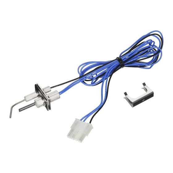
The Q3400A Igniter-Flame Rod Assembly replaces the
original igniter-flame rod assembly in the Q3450 and Q3480
Pilot Hardware used with the SV9500 and SV9600
SmartValve™ System. The Q3400A has a unique keyed
plug connector that will only fit the SV9500/SV9600 Sys-
tems.
This assembly can be replaced without removing the pilot
burner, see Fig. 1.
TEMPERATURE RATING:
Flame Rod Tip: 1800° F [982° C].
Igniter Insulator: 905° F [485° C].
Flame Rod Insulator: 1250° F [677° C].
Flame Rod Lead: 500° F [260° C].
WHEN INSTALLING THIS PRODUCT...
1. Read these instructions carefully. Failure to follow
them could damage the product or cause a hazardous condi-
tion.
2. Check the ratings and description given in the instruc-
tions to make sure the product is suitable for your application.
3. Installer must be a trained, experienced service techni-
cian.
4. After installation is complete, check out product op-
eration as provided in these instructions.
!
WARNING
FIRE OR EXPLOSION HAZARD
CAN CAUSE PROPERTY DAMAGE,
SEVERE INJURY, OR DEATH.
Follow these warnings exactly:
1. Disconnect power supply before removing any
connectors to prevent electrical shock or equip-
ment damage.
2. To avoid dangerous accumulation of fuel gas,
turn off gas supply at appliance service valve
before starting igniter-flame rod assembly re-
moval.
REMOVE OLD ASSEMBLY
1. Turn off power at circuit breaker or fuse box.
2. Hold the bottom of the assembly with one hand. With
the other hand, remove spring clip by pulling it away from the
pilot burner. See Fig. 1.
3. Remove the assembly from the pilot burner.
4. Disconnect the leadwires from the ignition system
control module.
5. Discard the old assembly and spring clip.
Igniter-Flame Rod Assembly
Application
Installation
G. S. • Rev. 7-94 • © Honeywell Inc. 1994 • Form Number 69-0751—2
1
Fig. 1—Replace Q3400A Igniter-Flame Rod
Assembly in keyed slot of pilot burner bracket.
Q3400A
PILOT
BURNER
SPRING
CLIP
MAKE SURE SPRING CLIP
IS FULLY OVER BOTH PILOT
BURNER AND IGNITER-
FLAME ROD BRACKETS.
IMPORTANT: Make sure the assembly is oriented in the
proper direction for installation into the pilot burner.
MOUNT REPLACEMENT ASSEMBLY
1. Insert assembly in the pilot burner until assembly is
flush with pilot burner bracket. Secure with new spring clip
provided. See Fig. 1.
2. Connect the igniter-flame rod assembly keyed plug to
Igniter connector on the ignition system control.
Startup and Checkout
1. Set thermostat to call for heat.
2. Watch the pilot burner during the ignition sequence.
See if:
a. Igniter glows red and pilot lights.
b. Igniter ceases to glow red after the pilot is lit.
c. Main burner lights.
3. If the ignition sequence is not as described, trouble-
shoot the system by following the procedures in the Service
section of the SV9500 SmartValve™ System Control In-
structions, form 69-0709.
Q3400A
TARGET
KEYED
SLOT
FLAME
ROD
IGNITER
IGNITER-
FLAME
ROD
ASSEMBLY
M9042
69-0751
Advertisement

Related Manuals for Honeywell Q3400A


Summary of Contents for Honeywell Q3400A
- Page 1 Service control module. section of the SV9500 SmartValve™ System Control In- 5. Discard the old assembly and spring clip. structions, form 69-0709. G. S. • Rev. 7-94 • © Honeywell Inc. 1994 • Form Number 69-0751—2 69-0751...
- Page 2 Home and Building Control Home and Building Control Helping You Control Your World Honeywell Inc. Honeywell Limited—Honeywell Limitée 1985 Douglas Drive North 740 Ellesmere Road Golden Valley, MN 55422 Scarborough, Ontario M1P 2V9 QUALITY IS KEY Printed in U.S.A.