
Related Manuals for Epson ICDmini 3.0


Summary of Contents for Epson ICDmini 3.0
- Page 1 CMOS 16-BIT SINGLE CHIP MICROCONTROLLER ICDmini Ver. 3.0 (S5U1C17001H3) User Manual Rev. 1.0...
- Page 2 2. This evaluation board/kit or development tool is intended for use by an electronics engineer and is not a consumer product. The user should use it properly and in a safe manner. Seiko Epson dose not assume any responsibility or liability of any kind of damage and/or fire coursed by the use of it. The user should cease to use it when any abnormal issue occurs even during proper and safe use.
-
Page 3: Table Of Contents
Appendix A Differences from ICDmini Ver. 2.0 ............15 Appendix B ICDmini Ver1.0, 1.1, and 2.0 Compatible Cable Specifications ....16 Pin Assignment Table ......................16 Component Specifications ....................16 Appendix C Operable Condition Examples (Reference) ...........17 Revision History......................18 ICDmini Ver. 3.0 User Manual Seiko Epson Corporation (Rev. 1.0) -
Page 4: Overview
The ICDmini Ver. 3.0 (S5U1C17001H3) is a hardware tool (emulator) that allows developers to efficiently develop software for the Seiko Epson S1C17 Family 16-bit microcontrollers (hereinafter referred as S1C17 MCU). The ICDmini Ver. 3.0 provides an interface function to connect the S1C17 MCU on the target system and the host computer and is capable being used for debugging and emulation of the target system software. -
Page 5: Features
The ICDmini Ver. 3.0 requires a PC equipped with a USB port as the host computer. For the operating systems supported, refer to the manual for the S1C17 Family C Compiler Package Ver. 3.0.0 or later. ICDmini Ver. 3.0 User Manual Seiko Epson Corporation (Rev 1.0) -
Page 6: Package Contents
Please prepare the item shown below, as it is not included in this package. • S1C17 Family C Compiler Package Ver. 3.0.0 or later Figure 2.1 Contents of ICDmini Ver. 3.0 Package ICDmini Ver. 3.0 User Manual Seiko Epson Corporation (Rev. 1.0) -
Page 7: Name And Function Of Each Part
This connector is used to connect the host computer using a USB cable. The ICDmini Ver. 3.0 should be connected directly to the USB port of the host computer. Figure 3.2.1 ICDmini Ver. 3.0 Left Side View ICDmini Ver. 3.0 User Manual Seiko Epson Corporation (Rev 1.0) -
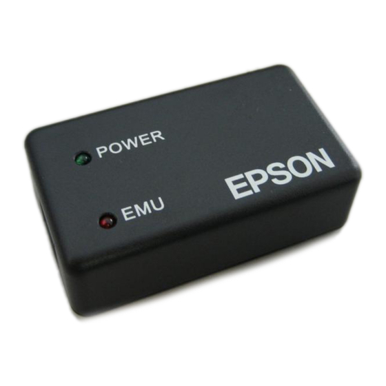
Page 8: Top Panel (Leds)
However, once this LED starts blinking by executing the target program, it continues blinking even if the power supply of the target system is turned off or the target system is disconnected after that. Figure 3.3.1 ICDmini Ver. 3.0 Top View ICDmini Ver. 3.0 User Manual Seiko Epson Corporation (Rev. 1.0) -
Page 9: Connections
Figure 4.1.1(b) Target System Connection Example 2 Note! Refer to the “Basic External Connection Diagram” in the Technical Manual for the target S1C17 MCU to determine the wiring and elements to be connected. ICDmini Ver. 3.0 User Manual Seiko Epson Corporation (Rev 1.0) -
Page 10: Target System Interface Connector
Flash memory programming voltage output – Ground TARGET_RST_OUT Target system reset signal output TARGET_VCC_IN – Target system power supply voltage input VCC3.3V – Power supply (3.3 V) N.C. – Unused ICDmini Ver. 3.0 User Manual Seiko Epson Corporation (Rev. 1.0) -
Page 11: Pin Description
When connecting the above signals to the target system, the connection destinations should be determined using the ICDmini Ver. 3.0 internal circuit configuration shown below as a reference. Figure 4.1.2.1 Configuration of ICDmini Ver. 3.0 Interface Power Supply and Reset Circuits ICDmini Ver. 3.0 User Manual Seiko Epson Corporation (Rev 1.0) -
Page 12: Connecting To The Host Computer
In addition to the POWER LED, the EMU (red) LED lights if power to the target system has been turned on and the target S1C17 MCU is ready to start debugging. Note! The VCC3.3V pin in the target system interface connector always outputs a voltage of 3.3 V. ICDmini Ver. 3.0 User Manual Seiko Epson Corporation (Rev. 1.0) -
Page 13: Firmware Update
An unused drive of the host computer is allocated to the ICDmini Ver. 3.0 as a storage device. The file explorer shows that the “firmware.bin” file exists in this drive. Replace this file with the latest firmware data file. ICDmini Ver. 3.0 User Manual Seiko Epson Corporation (Rev 1.0) - Page 14 Remove the jumper pin set in Step (2) and put it back into the original position. Then attach the bottom cover paying attention to the direction (align the side of the cover with the notch to the 10-pin connector side). ICDmini Ver. 3.0 User Manual Seiko Epson Corporation (Rev. 1.0)
-
Page 15: Precautions
• The ICDmini Ver. 3.0 should be used indoors. • Do not use the ICDmini Ver. 3.0 with the bottom cover left open except when the firmware is updated, as it may cause a malfunction. ICDmini Ver. 3.0 User Manual Seiko Epson Corporation (Rev 1.0) -
Page 16: Troubleshooting
→ Use the supplied cable without being extended. If it must be extended, use an extension cable as short as possible and shield the wiring to reduce low-level noise mixed in the DSIO signal. ICDmini Ver. 3.0 User Manual Seiko Epson Corporation (Rev. 1.0) -
Page 17: Specifications
20% to 85% No condensation 8.3 Electrical Characteristics Table 8.3.1 3.3 V Power Supply Pin Characteristics Pin name Item Min. Typ. Max. Unit VCC3.3V Current – – Voltage -5.0 – +5.0 ICDmini Ver. 3.0 User Manual Seiko Epson Corporation (Rev 1.0) -
Page 18: Appendix A Differences From Icdmini Ver. 2.0
S1C17803 (when used with a 24 MHz or higher OSC3 clock) Update using a file explorer on the Firmware update Update using debugger commands host computer *1 Includes a flash memory programming power supply pin ICDmini Ver. 3.0 User Manual Seiko Epson Corporation (Rev. 1.0) -
Page 19: Appendix B Icdmini Ver1.0, 1.1, And 2.0 Compatible Cable Specifications
Target system side connector Product Connector (4 pins): RE-04 (JST) Black connectors number Connector (2 pins): RE-02 (JST) Contact: RF-SC2210(LF)(SN) (JST) Connector (4 pins): PAP-04V-S (JST) White connector Contact: SPHD-002T-P0.5 (JST) ICDmini Ver. 3.0 User Manual Seiko Epson Corporation (Rev 1.0) -
Page 20: Appendix C Operable Condition Examples (Reference)
S1C17W23 1.2 V 1 MHz 100 cm max. S1C17801 3.3 V 24 MH (OSC3 = 48 100 cm max. MHz) S1C17803 5.0 V 20 MHz 100 cm max. ICDmini Ver. 3.0 User Manual Seiko Epson Corporation (Rev. 1.0) -
Page 21: Revision History
Revision History Revision History Attachment-1 Rev. No. Date Page Category Contents Rev. 1.0 2015/02/18 New establishment ICDmini Ver. 3.0 User Manual Seiko Epson Corporation (Rev 1.0) - Page 22 EPSON HONG KONG LTD. Unit 715-723, 7/F Trade Square, 681 Cheung Sha Wan Road, Kowloon, Hong Kong. Phone: +852-2585-4600 FAX: +852-2827-4346 EPSON TAIWAN TECHNOLOGY & TRADING LTD. 14F, No. 7, Song Ren Road, Taipei 110, TAIWAN Phone: +886-2-8786-6688 FAX: +886-2-8786-6660 EPSON SINGAPORE PTE., LTD.
- Page 23 Emulators/Simulators Click to view products by manufacturer: Epson Other Similar products are found below : AC244062 AC244064 SPC563M64CAL144 SPC563M64CAL176 ST7MDT2-EMU2B IM3316 IM1281B IM1275 IM1227 IM1259G IM1253B IM1253B(D) MJYS-QKJL-40/380V MJYS-QKJL-75/380V MJYD-JL-75/380V MJYD-JL-40/380V CI-B02CS01S CI-B03CS01S CI-BO3GS01S GD10PJX120L2S HEDS-9730#Q50 HEDS-9700#F50 L-MZ07 L-MZ02 L-MZ021 TXVT4G6M-S JL_MOD_FH_V1.0...