Sharp AX-1100 Service Manual
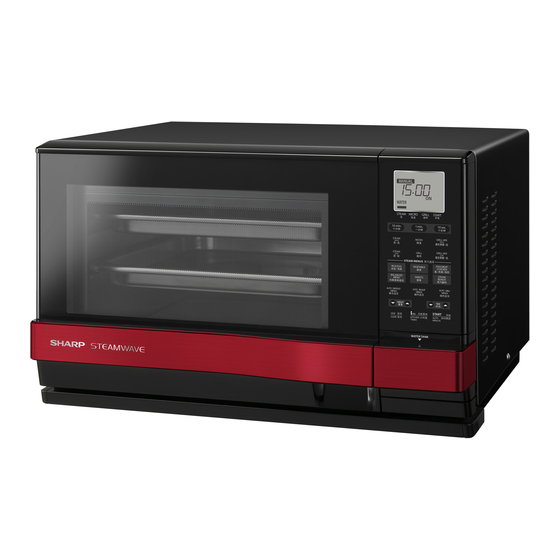
Microwave oven with steam and grill
Hide thumbs
Also See for AX-1100:
- Operation manual with cookbook (92 pages) ,
- Operation manual with cookbook (60 pages)
Table of Contents
Advertisement
TopPage
In the interests of user-safety the oven should be restored to its original condition and only parts identical to those
specified should be used.
CHAPTER 1. BEFORE SERVICING
CHAPTER 2. WARNING TO SERVICE PERSONNEL
CHAPTER 3. PRECAUTIONS FOR USING LEAD-
FREE SOLDER
CHAPTER 4. PRODUCT DESCRIPTION
CHAPTER 5. APPEARANCE VIEW
CHAPTER 6. OPERATION
CHAPTER 7. FUNCTION OF IMPORTANT COMPO-
NENTS
CHAPTER 8. TROUBLESHOOTING GUIDE
SERVICE MANUAL
MICROWAVE OVEN WITH
MODELS
CONTENTS
CHAPTER 9. TEST PROCEDURES
CHAPTER 10. ERROR LIST
CHAPTER 11. TEST MODE
CHAPTER 12. COMPONENT REPLACEMENT AND
ADJUSTMENT PROCEDURE
CHAPTER 13. MICROWAVE MEASUREMENT
CHAPTER 14. CIRCUIT DIAGRAMS
Parts List
S0005AX11PHR/T
STEAM AND GRILL
AX-1100(IN)
AX-1100(R)
This document has been published to be used for
after sales service only.
The contents are subject to change without notice.
AX1100(R)
Advertisement
Table of Contents

Related Manuals for Sharp AX-1100


Summary of Contents for Sharp AX-1100
- Page 1 TopPage AX1100(R) SERVICE MANUAL S0005AX11PHR/T MICROWAVE OVEN WITH STEAM AND GRILL AX-1100(IN) MODELS AX-1100(R) In the interests of user-safety the oven should be restored to its original condition and only parts identical to those specified should be used. CONTENTS CHAPTER 1. BEFORE SERVICING CHAPTER 9.
-
Page 2: Table Of Contents
CONTENTS CHAPTER 1. BEFORE SERVICING CHAPTER 10. ERROR LIST Error List ........... 10-1 CHAPTER 2. WARNING TO SERVICE PERSON- How to check in the event of an error ..10-2 CHAPTER 11. TEST MODE CHAPTER 3. PRECAUTIONS FOR USING LEAD- FREE SOLDER CHAPTER 12. -
Page 3: Chapter 1. Before Servicing
GENERAL IMPORTANT INFORMATION This Manual has been prepared to provide Sharp Corp. Service engineers with Operation and Service Information. It is recommended that service engineers carefully study the entire text of this manual, so they will be qualified to render satisfactory customer ser- vice. - Page 4 AX1100(R) CAUTION MICROWAVE RADIATION Personnel should not be exposed to the microwave energy which may radiate from the magnetron or other microwave generating devices if it is improperly used or connected. All input and output microwave connections, waveguides, flanges and gaskets must be secured.
-
Page 5: Chapter 2. Warning To Service Personnel
Indien het water nog steeds schroevedraaier kortsluit tegen het chassis. koud is, herhaalt u de allereerste drie stappen en controleer Sharp beveelt ten sterkste aan dat, voor zover mogelijk, nogmaals de aansluitingen naar de geteste onderdelen. defecten worden opgespoord wanneer de stekker uit het Wanneer alle reparaties zijn uitgevoerd en de oven weer in stopcontact is gehaald. - Page 6 AX1100(R) 2 – 2...
- Page 7 AX1100(R) Before replacing the Printed Wiring Board Some normal boards are found in board units that have been returned due to oven failure. So, most of board replacements may arise from poor har- ness connection. Accordingly, before replacing any board that was judged to require its replacement, use the following procedure to re-check that the connection terminal of a connector has been properly inserted: When the connectors have been incorrectly inserted to the control unit.
-
Page 8: Chapter 3. Precautions For Using Lead- Free Solder
AX1100(R) AX1100(R) Service Manual CHAPTER 3. PRECAUTIONS FOR USING LEAD-FREE SOLDER Employing lead-free solder The “Main PWB” of this model employs lead-free solder. This is indicated by the “LF” symbol printed on the PWB and in the service manual. The suffix letter indicates the alloy type of the solder. -
Page 9: Chapter 4. Product Description
AX1100(R) AX1100(R) Service Manual CHAPTER 4. PRODUCT DESCRIPTION [1] SPECIFICATIONS ITEM DESCRIPTION 230 Volts Power Requirements 50 Hertz Single phase, 3 wire grounded Steam cooking ---- 0.91 kW Approx. 4.0A Grill cooking --------1.1 kW Approx. 4.8A Power Consumption Combi cooking ---- 2.53 kW Approx. 11.4A Microwave cooking ---- 1.51 kW Approx. -
Page 10: Oven Diagram
AX1100(R) AX1100(R) Service Manual CHAPTER 5. APPEARANCE VIEW [1] OVEN DIAGRAM 1. Ventilation openings (at the bottom of the oven) Be aware that hot steam or air comes out during steam or combi cooking, and keep children away from the oven. 2. -
Page 11: Control Panel
AX1100(R) [2] CONTROL PANEL 1. Display information: The display shows useful information including cooking time and cooking mode. 1. Cooking mode & START indicators The indicator, just above each symbol, will fl ash or light up during the operation. You can press a concerned key when the indicators are flashing. When the indicators light up on the display, they mean that each cooking mode is selected or the oven is operating in each cooking mode. -
Page 12: Important Instructions
AX1100(R) [3] IMPORTANT INSTRUCTIONS Read Carefully Before Cooking with Steam 1. WATER TANK To fill the water tank with room temperature water suitable for drinking (filtered) is a must for cooking with steam. Be sure to follow the directions below. 1. - Page 13 AX1100(R) 3. Drain Water Function Perform the Drain Water function at least once a day after cooking with steam. It takes up to 7 minutes. Drain Water function is very useful to prevent scale build up and the use of stale water. It causes evaporation of the internal steam system. PROCEDURE 1.
-
Page 14: Chapter 6. Operation
AX1100(R) AX1100(R) Service Manual CHAPTER 6. OPERATION [1] Water supply/drainage schematic 1. When installing the water tank ENGINE UNIT ASSEMBLY Water supply tube to the engine as- FEED-WATER TANK sembly PUMP MOTOR DRIP TRAY Inserting the water tank delivers water to the tank joint. 2. - Page 15 AX1100(R) 3. When removing the water tank (Only remained water in the tank joint is discharged.) Remained water in the tube and the engine is not discharged even with the water tank removed. Removing the water tank discharges remained water in the tank joint to the drip tray. 4.
-
Page 16: Operation Of Electric Parts In Each Heating Mode
AX1100(R) [2] Operation of electric parts in each heating mode Start Start Microwave Grill Grill heating element Grill heating element Engine heating element Engine heating element Intake damper motor Intake damper motor Tube pump motor Tube pump motor Fan motor Fan motor Antenna motor Antenna motor... -
Page 17: Chapter 7. Function Of Important Com
AX1100(R) AX1100(R) Service Manual CHAPTER 7. FUNCTION OF IMPORTANT COMPONENTS [1] DOOR OPEN MECHANISM 3. If the door is opened and the monitored interlock switch SW1 con- tacts (COM-NO) fail to open, the fuse F2 (F8A) blows immediately 1. The door lever is gripped and the door open handle is pulled. after closing of the monitor switch (COM-NC) contacts. -
Page 18: Thermal Cut-Out
AX1100(R) 4. The large electric currents flow through the high voltage winding of [9] THERMISTOR the high voltage transformer. 5. The large electric currents beyond 8A flow through the primary 1. THERMISTOR (ENGINE) TH1 winding of the high voltage transformer. The thermistor is a negative temperature coefficient type. -
Page 19: Chapter 8. Troubleshooting Guide
AX1100(R) AX1100(R) Service Manual CHAPTER 8. TROUBLESHOOTING GUIDE When troubleshooting the microwave oven, it is helpful to follow the Sequence of Operation in performing the checks. Many of the possible causes of trouble will require that a specific test be performed. These tests are given a procedure letter which will be found in the “Test Procedure” section. IMPORTANT: If the oven becomes inoperative because of a blown fuse F2 (F8A) in the monitored latch switch - monitor switch circuit, check the monitored latch switch and monitor switch before replacing the fuse F2 (F8A). - Page 20 A B C D E E E E E G G H H H I J K L L M N TEST PROCEDURE POSSIBLE CAUSE DEFECTIVE PARTS PROBLEM CONDITION Home fuse or breaker blows when power supply cord is plugged into wall outlet.
-
Page 21: Chapter 9. Test Procedures
AX1100(R) AX1100(R) Service Manual CHAPTER 9. TEST PROCEDURES [1] A: MAGNETRON TEST NEVER TOUCH ANY PART IN THE CIRCUIT WITH YOUR HAND OR AN INSULATED TOOL WHILE THE OVEN IS IN OPERATION. CARRY OUT 3D CHECKS. Isolate the magnetron from the high voltage circuit by removing all leads connected to the filament terminal. To test for an open circuit filament use an ohmmeter to make a continuity test between the magnetron filament terminals, the meter should show a reading of less than 1 ohm. -
Page 22: B: High Voltage Transformer Test
AX1100(R) 1000g 1000g 1000g T1 C T2 C Heat up for 50 sec. [2] B: HIGH VOLTAGE TRANSFORMER TEST WARNING: High voltages and large currents are present at the secondary winding and filament winding of the power transformer. It is very dangerous to work near this part when the oven is on. -
Page 23: E: Switch Test
AX1100(R) [5] E: SWITCH TEST CARRY OUT 3D CHECKS. Isolate the switch to be tested and using an ohmmeter check between the terminals as described in the following table. Table: Terminal Connection of Switch Plunger Operation Common terminal to Normally open terminal Common terminal to Normally close terminal Released Open circuit... -
Page 24: J: Blown Fuse (F2) F8A (Noise Filter)
AX1100(R) [10] J: BLOWN FUSE (F2) F8A (NOISE FILTER) CARRY OUT 3D CHECKS. 1. If the fuse F2 F8A is blown when the door is opened, check the monitored interlock switch and monitor switch. 2. If the fuse F2 F8A is blown by incorrect door switching replace the defective switch(es) and the fuse F2 F8A. 3. -
Page 25: N: Key Unit (Membrane Switch) Test
AX1100(R) 2.2. In connection with indicators 1) At a certain digit, all or some segments do not light up. 2) At a certain digit, brightness is low. 3) Only one indicator does not light up. 4) The corresponding segments of all digits do not light up; or they continue to light up. 5) Wrong figure appears. -
Page 26: Chapter 10. Error List
AX1100(R) AX1100(R) Service Manual CHAPTER 10. ERROR LIST [1] Error List Error Application Check method Detail of error Error condition Check timing Note display code menu Defrost Oven temperature Oven temperature is too “HOT” is blinking Steam Low Grill thermistor Immediately is high. -
Page 27: How To Check In The Event Of An Error
AX1100(R) [2] How to check in the event of an error 1. How to check water supply performance Check the plumbing of the tubes. If the plumbing is normal, check the performance of the tube pump assembly. 1) Check of plumbing Are tubes bended? Are tubes broken? Repair or exchange the tube. - Page 28 AX1100(R) 2. How to check performance of thermistor (Engine) Set the water tank, which has been filled with water to the MAX mark, to the set and power ON. (Confirm that there is no water remaining in the oven cavity.) Set the test mode to 10.
- Page 29 AX1100(R) 5. EE12 Engine thermistor failure Is the connectors between the thermistor (Engine), and wire harness disconnected or short circuited? Connect/repair the connector(s) or replace the thermistor/harness. Measure the thermistor (Engine) resistance using a tester with the thermistor connector pulled out of the control unit. The thermistor (engine) resistance is within its appropriate range.
- Page 30 How to operate test mode (power on and door closed) [STOP/CLEAR [STEAM HIGH [MICRO] [door open](show ROM version) ([test number is selected by [WEIGHT UP/DOWN] [initial number: 04]) [or push direct select key] START] within 3 sec test name detail of test output example of display A/D data monitor...
- Page 31 test name detail of test output example of display RY-1, EH, PM, FM Water drain Pushing [START] key water draining works. *To empty the water of the tank. I. DAMPER: OPEN *After work for 60 sec. (FLASH: EP_MN_PO), the next stage start. *Flashing the right-side bar.
-
Page 32: Chapter 11. Test Mode
test name detail of test output example of display (1) Push "START". PM starts. RY-1, FM, PM TOTAL TEST I. DAMPER: OPEN direct select key: [info] After 30 sec. how to operate at production MICRO (0%) line MICRO (100%) power on "... -
Page 33: Chapter 12. Component Replacement And Adjustment Procedure Before Operating
4) If the outer case cabinet is not fitted. 2) Door hinge, support or latch hook is damaged. WARNING FOR WIRING To prevent an electric shock, take the following manners. 3) Sharp edge: 1. Before wiring, Bottom plate, Oven cavity, Waveguide flange, Chassis support and other metallic plate. -
Page 34: High Voltage Components Removal
AX1100(R) [3] HIGH VOLTAGE COMPONENTS REMOVAL (HIGH VOLTAGE CAPACITOR AND HIGH VOLTAGE RECTIFIER ASSEMBLY) To remove the components, proceed as follows. 5. Remove one (1) screw holding earth side terminal of the high volt- age rectifier assembly. 1. CARRY OUT 3D CHECKS. 6. -
Page 35: Pump Motor Removal
AX1100(R) Hold the centre of the bracket which supports the shaft of the CAUTION: • Do not hit the fan blade when installing because the fan motor on a flat table. bracket may be deformed. ii) Apply the screw lock tight into the hole (for shaft) of the fan •... -
Page 36: Engine Unit Assembly Removal
AX1100(R) 7. Remove the one (1) screw holding the tank joint to the tank cover. 13.Remove the two (2) screws holding the lower hinge to the bottom plate, and remove the lower hinge. 8. Remove the tank joint from the tank cover. 14.Remove the one (1) screw holding the tank cover to the bottom CAUTION: When the joint tube or pump tube L is removed from the plate (right side). -
Page 37: Power Supply Cord Replacement
AX1100(R) [16] POWER SUPPLY CORD REPLACEMENT 1. REMOVAL 2. REINSTALLATION 1. CARRY OUT 3D CHECKS. 1. Insert the moulding cord stopper of power supply cord into the square hole of the cavity back plate, referring to the figure. 2. Remove the one (1) screw holding the green/yellow wire to the cav- ity back plate. -
Page 38: Monitored Interlock Switch, Monitor Switch And Door Sensing Switch Removal
AX1100(R) [19] MONITORED INTERLOCK SWITCH, MONITOR SWITCH AND DOOR SENSING SWITCH REMOVAL 1. CARRY OUT 3D CHECKS. 2. Remove the water tank. 3. Remove the control panel assembly, referring to “CONTROL UNIT REMOVAL”. SW2: Monitor switch 4. Remove the one (1) screw holding the tank cover to the bottom plate (right side). -
Page 39: Door Replacement
AX1100(R) [21] DOOR REPLACEMENT 1. REMOVAL LATCH HEAD U, LATCH HEAD L, SPRING AND DOOR FRAME DOOR FRAME ASSEMBLY AND DOOR COVER 15.Remove the two (2) screws holding the latch angle to the door 1. Disconnect the oven from the power supply. frame. -
Page 40: Installation Of Door Packing
AX1100(R) 3. After any service, make sure of the following: 1. Door latch heads smoothly catch latch hook through latch holes Upper and that latch head goes through centre of latch hole. Oven Hinge Deviation of door alignment from horizontal line of cavity face plate is to be less than 1.0mm. -
Page 41: Plumbing
AX1100(R) [23] PLUMBING Hose band Engine unit assembly Joint tube Tube Hose bands Hose band Water tube Tank joint Pump tube L Hose band Tube pump assembly 12 – 9... -
Page 42: Chapter 13. Microwave Measurement
AX1100(R) AX1100(R) Service Manual CHAPTER 13. MICROWAVE MEASUREMENT After adjustment of door latch switches, monitor switch and door are completed individually or collectively, the following leakage test must be per- formed with a survey instrument and it must be confirmed that the result meets the requirements of the performance standard for microwave oven. REQUIREMENT The safety switch must prevent microwave radiation emission in excess of 5mW/cm at any point 5cm or more from external surface of the oven. -
Page 43: Chapter 14. Circuit Diagrams Pictorial Diagram
AX1100(R) AX1100(R) Service Manual CHAPTER 14. CIRCUIT DIAGRAMS [1] PICTORIAL DIAGRAM 1. CONTROL UNIT 14 – 1... - Page 44 AX1100(R) 2. OTHER COMPONENTS POWER SUPPLY CORD Engine unit assembly G–Y (Engine heating elemnt) TC3: Engine thermal cut-out F 8 A NOISE FILTER TC2: Oven thermal cut-out Chassis support TC1: FM: Fan motor Magnetron thermal cut-out GH: Grill heating element (Oven assembly) OL: Oven lamp SW2: Monitor switch...
- Page 45 230V ~50Hz F1: SPECIAL FUSE 0.22u/250V 10M/0.5W NOISE SUPPRESSION COIL 4700p/250V 680K/0.5W 4700p/250V CONTROL UNIT INTAKE DAMPER MOTOR FAN MOTOR PUMP MOTOR TH1: THERMISTOR (ENGINE) TH2: THERMISTOR (GRILL) SW5: ANTENNA SWITCH SW4: INTAKE DAMPER SWITCH SW3: DOOR SENSING SWITCH OVEN LAMP ANTENNA MOTOR ENGINE HEATING ELEMENT (Engine unit assy) (900W)
-
Page 46: Control Unit Circuit
AX1100(R) [3] CONTROL UNIT CIRCUIT 14 – 4... -
Page 47: Parts List
AX1100(R) PartsGuide PARTS LIST MICROWAVE OVEN WITH STEAM AND GRILL AX-1100(IN) MODELS AX-1100(R) Parts marked "*" may cause undue microwave exposure. Parts marked " " are used in voltage more than 250V. CONTENTS OVEN PARTS ACCESSORY PARTS AND PACKING DOOR AND CONTROL PANEL ... - Page 48 AX1100(R) [1] OVEN PARTS 9-10 8-50 8-49 9-27 9-10 8-28 9-20 8-38 8-24 8-36 9-15 9-20 8-35 8-51 8-22 8-25 1-1-1 8-52 9-26 8-32 8-26 8-27 9-15 9-14 8-30 9-23 8-44 9-11 8-37 9-12 9-13 9-12 9-14 8-14 8-53 9-21 8-46 9-17 9-11...
- Page 49 AX1100(R) PRICE PART PARTS CODE DESCRIPTION RANK MARK RANK [1] OVEN PARTS ELECTRIC PARTS RMOTDA280WRZZ Turntable Motor (Antenna motor) RC-QZA352WRZZ HV Capacitor RMOTDA280WRZZ Intake Damper Motor CHET-A024WRKZ Engine Unit Assembly(Engine heating element) QFS-BA009WRE0 Fuse 20A (Special fuse) QFS-BA012WRZZ Fuse 20A (Special fuse) (Interchangeable) RMOTEA478WRZZ Fan Motor RV-MZA347WRZZ...
- Page 50 AX1100(R) PRICE PART PARTS CODE DESCRIPTION RANK MARK RANK [1] OVEN PARTS MHNG-A648WRMZ 8-30 Upper Hinge MHNG-A651WRMZ 8-31 Lower Hinge MJNTPA018WRPZ 8-32 Tube 8-33 PCUS-A276WREZ Tank Cover Cushion 8-34 LBND-A029WREZ Pin band PTUBXA074WREZ 8-35 Joint Tube PCUS-A298WREZ 8-36 Top Cushion PDUC-B203WRPZ 8-37 Fan Duct...
- Page 51 AX1100(R) [2] DOOR AND CONTROL PANEL PARTS 6-13 6-12 6-17 6-17 6-17 6-18 6-17 6-17 6-16 6-16 6-11 6-16 6-17 6-10 6-16 6-17 6-17 5-2-2 6-15 5-2-1 6-14 PRICE PART PARTS CODE DESCRIPTION RANK MARK RANK [2] DOOR AND CONTROL PANEL PARTS CONTROL PANEL PARTS DPWB-A967DRKZ Control Unit...
- Page 52 AX1100(R) [3] ACCESSORY PARTS AND PACKING 90-11 Drip tray 90-9 90-6 90-12 90-8 90-7 WARRANTY CARD 90-16 90-2 90-15 90-1 90-17 90-4 90-1 90-10 90-13 90-18 90-3 90-5 PRICE PART PARTS CODE DESCRIPTION RANK MARK RANK [3] ACCESSORY PARTS AND PACKING 90-1 PSRA-A076WRWZ Steam Tray...
- Page 53 AX1100(R) INDEX PRICE PART PRICE PART PARTS CODE PARTS CODE RANK MARK RANK RANK MARK RANK PDUC-B201WRFZ 1-8-13 [ C ] PDUC-B203WRPZ 1-8-37 CHET-A024WRKZ 1-EH PFPF-A316WREZ 1-8-38 CPADBA445WRKZ 3-90-3 PGID-A109WRFZ 1-8-39 [ D ] PGID-A110WRFZ 1-8-40 DDORFB468WRYZ 2-6-1 PGIDMA023WRFZ 1-8-41 DPWB-A967DRKZ 2-5-1 PGLSPA743WREZ...
- Page 54 AX1100(R) PRICE PART PARTS CODE RANK MARK RANK XCPS730P14000 1-9-5 XCPS740P08000 1-9-19 XCTS740P08000 1-9-3 XEPS730P10X00 1-9-25 " 2-5-3 XEPS740P08000 1-PM-5 " 2-6-17 XEPS740P10000 1-9-21 XEPS740P12000 2-6-18 XETS740P08000 1-9-22 XETS840P12000 2-6-16 XFPWW30P06K00 1-9-14 XHBS730P06000 1-9-28 XHBS730P08000 1-9-7 XHPS740P06K00 1-9-24 XHPS740P08000 1-9-23 XHPS740P08K00 1-9-6 "...
- Page 56 EndPage COPYRIGHT © 2010 BY SHARP CORPORATION ALL RIGHTS RESERVED. No part of this publication may be reproduced, stored in retrieval systems, or transmitted in any form or by any means, electronic, mechanical, photocopying, re- cording, or other wise, without prior written permission...