Table of Contents
Advertisement
Quick Links
Fiber Adapters For Camera Link
D-A-CH
Laser 2000 GmbH
82234 Wessling
Tel. +49 8153 405-0
info@laser2000.de
www.laser2000.de
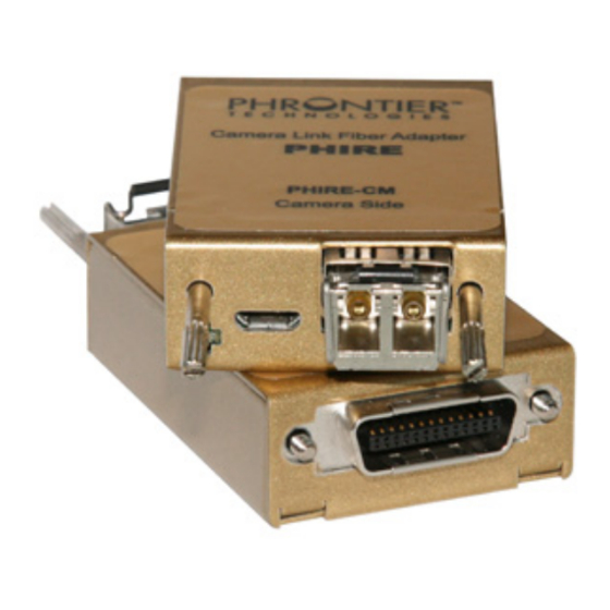
PHIRE
FrAnCe – Telecom
Laser 2000 SAS
78860 St-N. l. Bretèche
Tel. +33 1 30 80 00 60
info@laser2000.fr
www.laser2000.fr
TM
FrAnCe – Photonic
IberIA
Laser 2000 SAS
Laser 2000 SAS
33600 Pessac
28034 Madrid
Tel. +33 5 57 10 92 80
Tel. +34 617 308 236
info@laser2000.fr
info@laser2000.es
www.laser2000.fr
www.laser2000.es
User Manual
Revision 4
PHx-xx-Mxxx, PHx-xx-Sxx
PHR-6x-M025-E
norDICs
Laser 2000 GmbH
112 51 Stockholm
Tel. +46 8 555 36 235
info@laser2000.se
www.laser2000.se
Advertisement
Table of Contents
Troubleshooting

Summary of Contents for CAMERA LINK PHRONTIER PHIRE PHR-68-M025
- Page 1 PHIRE Fiber Adapters For Camera Link User Manual Revision 4 PHx-xx-Mxxx, PHx-xx-Sxx PHR-6x-M025-E D-A-CH FrAnCe – Telecom FrAnCe – Photonic IberIA norDICs Laser 2000 GmbH Laser 2000 SAS Laser 2000 SAS Laser 2000 SAS Laser 2000 GmbH 82234 Wessling 78860 St-N. l. Bretèche...
-
Page 2: Table Of Contents
4. Installation ..........................4 5. Functionality .......................... 5 5.1. DC Power Input Port ....................... 6 5.2. Camera Link Port & PoCL compatibility ................6 5.3. LED Status Indicators ..................... 7 5.4. Optical I/O Port ....................... 7 5.5. Optical Fiber Cable ......................8 6. -
Page 3: Introduction
10 km (6.25 miles) 7 km (4.38 miles) Camera Link interface bit assignment defined in Camera Link standard annex C CL Port A0 A1 A2 A3 A4 A5 A6 A7 B0 B1 B2 B3 B4 B5 B6 B7 C0 C1 C2 C3 C4 C5 C6 C7 √... -
Page 4: Single Fiber Models (Phire-S Series)
Users would need the following items for proper installation. 1. Camera Link compatible camera 2. Camera Link compatible frame grabber 3. Correct type of optical fiber cable (single mode or multi-mode, corresponding to the purchased PHIRE models) with correct connectors at both ends 4. -
Page 5: Functionality
STEP INSTALLATION STEPS Power off camera and frame grabber Plug PHIRE-CM module to the camera and secure the module with thumb screws Plug PHIRE-FG module to the frame grabber and secure the module with thumb screws Take off the caps on LC connectors at both ends of optical fiber cable. Take off the caps on the LC fiber ports of PHIRE-CM and PHIRE-FG. -
Page 6: Dc Power Input Port
CC3, CC4 and a bi-directional serial port (Figure 1). The exact bit assignment is defined in Appendix C of the Camera Link standard. PHx-68 supports max. 24 bit of image data with up to 68MHz of pixel clock rate. PHx-85 supports up to 24 bit of image data with up to 85MHz pixel clock rate. -
Page 7: Led Status Indicators
CM Module FG Module MDR26 pin 1 & 26 Supply 12V DC to camera Withdraw 12V DC from frame grabber MDR26 pin 13 & 14 Power return Power return Electrical current Supply 0.4A to camera Withdraw 0.2 A from frame grabber Table 2 PoCL features and pin assignment on MDR26 plug 5.3. -
Page 8: Optical Fiber Cable
connector port and is responsible for converting optical signals into electrical signals. Figure 3 shows the correct optical fiber connection. CM-Base FG-Base Figure 3 Optical fiber connection Since the active area of the optical port is smaller than the intersection of a human hair, any dust, soil or fiber debris can contaminate the optical I/O port and degrade system performance. -
Page 9: Technical Specifications
0.160 A @12V each module Typical Power Consumption 1.9 W each module Connector Type Micro USB type B with custom pin assignment Approx. Weight (each module) 75 gram 6.2. Camera Link Interface 6.2.1. Two fiber models PHR-68-M025 PHR-85-M025 PHR-85-M020 Models... -
Page 10: Optical Interface
6.3. Optical Interface 6.3.1. Two fiber models PHR-68-M025 PHR-68-S10 Models PHR-85-M025 PHR-85-S10 PHR-85-M020 PHR-85-S07 Operating Wavelength 850 nm 1310 nm Min Optical Tx Output Power -9.5 dBm -9 dBm Min Optical Rx Power -17 dBm -18 dBm Connector Type LC duplex LC duplex 50/125 µm or 62.5/125 µm 9/125 µm SM fibers... -
Page 11: Trouble Shooting
With Mounting Flange Options 7. Trouble Shooting: Although the PHIRETM products are designed to be plug-and-play and user friendly, users may encounter some abnormal system operations in practice. The table below lists some possible abnormal operations that can be easily corrected by users before sending the units back to our technical support for investigation. -
Page 12: Product Safety And Regulatory Compliance
ON Blink OFF OFF a) PHIRE-FG no power a) Check PHIRE-FG power connection b) Fuse burn off on the FG and reset camera and PHIRE system module, possible causes b) Send back the unit to Phrontier Tech including current or voltage surge or authorized distributors for fuse from direct DC power on or due replacement... -
Page 13: Contact Us
9. Contact Us: Thank you for purchasing the PHIRE™ products. We hope you enjoy all the benefits brought to you by the unique design and functionalities. If you need any assistance, please contact your distributor. You may also contact us via: Phone: 866-389-2829 (Toll free for US and Canada) Fax: 801-998-1855...