Table of Contents
Advertisement
User Guide
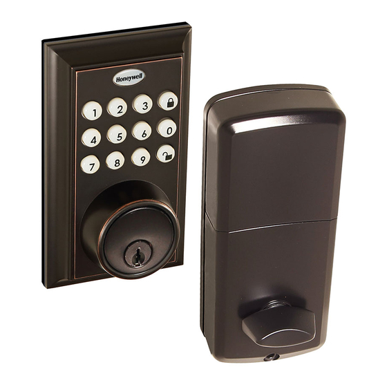
Square Faceplate Digital Bluetooth Deadbolt
Package Includes:
1 - Exterior Faceplate
1 - Interior Faceplate
1 - User Guide
2 - Keys
Exterior Faceplate
Interior Faceplate
1 3/8" Screws
Please carefully check the above list to confirm all items have been received. If any items are
missing, please contact Consumer Assistance. ( See page for contact information)
Read this manual carefully before installing and operating!
1 - Strike Plate
1 - Mounting Plate
1 - Deadbolt Latch
1 - 1 3/8" Screws
User Guide
Keys
1" Screws
5/16" Screws
2 - 5/16" Screws
2 - 1 " Screws
5 - 3/4" Screws
Mounting Plate
Strike plate
3/4" Screws
ENGLISH
Model 8812309S
8812409S
Deadbolt Latch
Advertisement
Table of Contents

Related Manuals for Honeywell 8812309S


Summary of Contents for Honeywell 8812309S
- Page 1 ENGLISH User Guide Square Faceplate Digital Bluetooth Deadbolt Model 8812309S 8812409S Package Includes: 1 - Exterior Faceplate 1 - Strike Plate 2 - 5/16” Screws 1 - Interior Faceplate 1 - Mounting Plate 2 - 1 “ Screws 1 - User Guide 1 - Deadbolt Latch 5 - 3/4”...
-
Page 2: Table Of Contents
INDEX I. INSTALLATION INSTRUCTIONS Product Overview / Tools Required......................Page 1 Prepare Door and Jamb..........................Page 2 Adjusting Deadbolt Latch Set........................Page 3 Installing Deadbolt Latch Set........................Page 4 Preparing Interior Assembly........................Page 5 Installing Exterior Assembly........................Page 6 Installing Interior Assembly........................Page 7-8 II. -
Page 3: Installation Instructions
INSTALLATION INSTRUCTIONS PACKAGE CONTENTS Entry keys (2 ea.) Deadbolt Latch Set (Adjustable) 2-3/8” (60mm) to 2-3/4” (70mm) Mounting Plate Interior Assembly Exterior Assembly Deadbolt Strike Plate 5/16” (8mm) Screws - 2 ea. 7/8” (22mm) Screws - 2 ea. 3/4” (19mm) Screws - 5 ea. 1” (25mm) Screw - 1 ea. TOOLS REQUIRED Tools Required for Installation Tools Required for Installation on Pre-drilled Doors:... -
Page 4: Prepare Door And Jamb
PREPARE DOOR AND JAMB NOTE: For installation on doors with pre-drilled holes skip to page 4. 1. TEMPLATE a. Cut out template printed on page 15 of this Manual (Figure 1a). b. Fold template and place on door 36” (915mm) from the ground as marked (Figure 1b). -
Page 5: Adjusting Deadbolt Latch Set
ADJUSTING DEADBOLT LATCH SET NOTE: Deadbolt Latch Set is shipped with the backset set at 2-3/8” (60mm) Measure the backset (backset is distance between edge of the door and the center of Lock). 1. TO CONVERT FROM 2-3/8” (60mm) BACKSET TO 2-3/4” (70mm) BACKSET a. -
Page 6: Installing Deadbolt Latch Set
INSTALLING DEADBOLT LATCH SET 3. INSTALLING THE DEADBOLT LATCH SET (need phillips head screwdriver) a. Insert Deadbolt Latch Set into door edge hole with the word “UP” and the arrow on the extension plate facing UP. Cross shaped spindle connector will be at the bottom of the Deadbolt Latch Set (Figure 3a). -
Page 7: Preparing Interior Assembly
PREPARING THE INTERIOR ASSEMBLY 5. UNPACK THE INTERIOR ASSEMBLY a. Remove the battery cover by sliding the cover upward. b. Locate the screws holding the Mounting Plate to the Interior Assembly. Remove the screws to release the Mounting Plate from the Interior Assembly. 6. SET THE ENTRY SWITCH FOR LEFT OR RIGHT HANDED DOOR a. Gently move the switch to “L” for Left Handed Door (Figure 6a). b. Gently move the Switch to “R” for Right Handed Door (Figure 6b). -
Page 8: Installing Exterior Assembly
INSTALLING EXTERIOR ASSEMBLY 8. INSTALLING THE EXTERIOR ASSEMBLY Work with the Door Open for easy access. a. Unpack the Exterior Assembly. Use care to not scratch the green circuit board during handling and installation. b. Check that the Rubber Gasket is properly seated on the Exterior Assembly (Figure 8a). c. Insert the Exterior Assembly onto the door with the tailpiece going through the Deadbolt Latch Set cross shaped spindle connector in the VERTICAL POSITION. Route the Control Wire through the door under the Deadbolt Latch Set (Figure 8c). -
Page 9: Installing Interior Assembly
INSTALLING INTERIOR ASSEMBLY 11. ATTACH THE CONTROL WIRE TO THE INTERIOR ASSEMBLY a. Use care to attach the Control Wire male plug to the Interior Assembly female socket connector. b. Carefully insert the male plug, smooth side up, into the female socket on the interior assembly. DO NOT FORCE! (Figure 11a). - Page 10 Insert 4 AA high quality Alkaline batteries into the Battery Compartment in the direction noted +/- on the Compartment. The Lock will beep 2 times, the keypad will illuminate blue, and the Honeywell button will flash green twice to signify that it has received power (Figure 13a). NOTE: Do not touch the Keypad until the blue light turns off.
- Page 11 App. Administrative & Authorized Users APPLICATION SETUP OPTIONS After you have installed your Bluetooth Lock, download the free “Honeywell Lock” App on your smart phone using one of the following options: 1. Search “Honeywell Lock” in the App Store or Google Play Store.
-
Page 12: Connect To Lock / Lock Settings
CONNECT TO BLUETOOTH LOCK IMPORTANT: Your Bluetooth must be enabled and you must be within range of the lock. 1. Press any key on Lock to activate the Lock. (Digital keys are lit when activated). 2. Click the “+” icon on the start screen. 3. Select which type of lock you would like to add 4. -
Page 13: Lock And Unlock
USING APP TO LOCK AND UNLOCK UNLOCK DOOR WITH THE APP 1. Open App, choose Lock and Touch App to Unlock Open App & Touch 2 Keys to Unlock LOCK DOOR WITH THE APP Open the App Click on the connected safe you wish to lock Press and hold the lock button until the safe has locked. AUTO LOCK If enabled in “Lock Settings”, it will automatically lock after 20 to 900 seconds. -
Page 14: System Settings
SYSTEM SETTINGS Go to the Main menu by pressing the * icon at the top left corner of the screen. Select “System Settings” Select below settings as desired. PATTERN PASSWORD Create a pattern to unlock the App. Provides extra security BEEP ON UNLOCKING Mute or enable a sound when the door is unlocked VIBRATION... -
Page 15: Account Management/Notifications
ACCOUNT MANAGEMENT Go to the Main menu by pressing the * icon at the top left corner of the screen. Select “Account Management” Select below settings as desired. PROFILE PICTURE Click on the picture at the top of the page Change the picture associated with the account by clicking the icon NICKNAME Click on “Nickname”. -
Page 16: Send Passcodes And Ekeys
4. Input the mobile number, or email address you would like to send the Passcode to 5. Press “Send by email” or “Send by Msg. ” CREATE AND SEND EKEYS To send an eKey, the receiver must have a Honeywell App account. The operation will fail if the Receiver is not regis- tered, or the wrong information is input when sending an eKey. SENDING EKEYS 1. -
Page 17: Manage Users
MANAGE USERS Ensure that WiFi is connected and working in order to manage Users associated with a connected lock FREEZE A USERS’ EKEY Select the lock with the eKey you want to Freeze Select the in the bottom menu Select the User you would like to Freeze Select “Freeze” Confirm that you would like to Freeze the User CHANGE AU TO A 1. Only A can authorize other Users. An AU can send eKeys and Passcodes to other Users. Select the lock with the eKey you want to authorize Select the in the bottom menu Select the top eKey tab 5. Select the User you would like to authorize... - Page 18 MANAGE USERS CLEAR USER EKEYS Select the lock with the eKeys you want to clear Select the in the bottom menu Select the top right icon Select “Clear” Input your account password Confirm the action RESET USER EKEYS When you reset eKeys, all eKeys will be removed from the lock. Select the lock with the eKeys you want to reset Select the in the bottom menu...
- Page 19 MANAGE USERS RESET PASSCODES When you reset eKeys, all eKeys will be removed from the lock. Select the lock the Passcode is associated with Select the in the bottom menu Select “Passcode” from the top tab Select the Dropdown icon Choose “Reset Passcode” from the top selections Input your account password 7. Confirm the action...
-
Page 20: Keypad Programming
Administrator Passcode: (Admin Passcode is located on the Honeywell App under Lock Settings.) -
Page 21: Turn On/Off Auto Lock Function
- Green light and beep c. 5 VERY IMPORTANT If you have connected the lock to the Honeywell e. Input time (20 - 900 seconds, and 00 to turn off) Lock Application, the default Passcode “1234” will no longer work; and you will have to use the - Green light and beep from the App, which should be changed after 2. -
Page 22: Add Administrator
PROGRAMMING PHYSICAL KEYPAD 5. ADD ADMINISTRATOR To add the administrator you must use the App. Press any button on the keypad to wake up lock in order to connect. 6. CUSTOMIZE PASSCODES RECEIVED FROM THE APP a. Input the VERY IMPORTANT - Green light and beep In order to change a Passcode, the Passcode c. 1 must have been sent from the App, and used by the Receiver. -
Page 23: Troubleshooting
TROUBLESHOOTING Issue Solution -Latch Working Direction switch is set to incorrect setting Backwards. • Remove the Interior Assembly and move the switch to the opposite direction. -Lock unlocks when lock • Check that your switch is set in the correct position Left or Right Handed door. button is pushed or locks If Correct when unlock button or code... -
Page 25: Template
BACK OF TEMPLATE... -
Page 26: Consumer Assistance
CONSUMER ASSISTANCE EMAIL: LHLPCustomerService@LHLPinc.com WEBSITE: www.honeywellsafes.com ADDRESS: Consumer Assistance Dept. LH Licensed Products, Inc., 860 East Sandhill Avenue Carson, CA 90746 USA TELEPHONE: US/Canada 1-800-860-1677 Ext. 1801 (Toll Free) Mexico 01-800-288-2872 After English voice recording stops you must then enter 800-860-1677 to complete your call. (Toll Free) Australia 0011-800-5325-7000 (Toll Free) Germany/New Zealand 00-800-5325-7000 (Toll Free) Other Countries XX*-310-323-5722 (Toll Charges Apply) XX*- Dial U.S. Country Code first CALL CENTER HOURS: US/Canada 8am – 5pm (Pacific**) Mon – Fri (Subject to change) CALL BACK HOURS: Other Countries 8am – 5pm (Pacific**) Mon – Fri (Subject to change) Pacific**- Local time in Los Angeles, CA, USA * Insert correct Country Code ** Local Time based on Los Angeles California USA INTERNATIONAL CALL BACK HOURS: If you need to speak with a consumer assistant and cannot contact us during the Call... -
Page 27: Fcc Compliance
FCC COMPLIANCE Regulatory Compliance This product complies with standards established by following regulatory bodies: - Federal Communications Commission (FCC) This device complies with Part 15 of the FCC rules. Operation is subject to the following two conditions: (1) This device may not cause harmful interference, and (2) This device must accept any interference, including interference that may cause undesired operation IMPORTANT! Changes or modifications not expressly approved by the manufacturer could void the user’s authority to operate the equipment. -
Page 28: Warranty
LH Licensed Products, Inc. may be brought by the original residential purchaser more than one (1) year after the cause of action has arisen. The Honeywell Trademark is used under license Manufactured by: from Honeywell International Inc. Honeywell LH Licensed Products, Inc. International Inc. makes no representations or 860 East Sandhill Avenue warranties with respect to this product.