Table of Contents
Advertisement
Advertisement
Table of Contents

Related Manuals for Asus ROG STRIX B360-I GAMING


Summary of Contents for Asus ROG STRIX B360-I GAMING
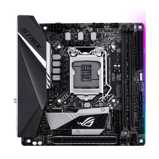
- Page 1 STRIX B360-I GAMING...
- Page 2 Product warranty or service will not be extended if: (1) the product is repaired, modified or altered, unless such repair, modification of alteration is authorized in writing by ASUS; or (2) the serial number of the product is defaced or missing.
-
Page 3: Table Of Contents
Contents Safety information ....................... v About this guide ......................vi ROG STRIX B360-I GAMING specifications summary .......... viii Package contents ...................... xii Installation tools and components ................. xiii Chapter 1: Product Introduction Motherboard overview ................1-1 1.1.1 Before you proceed ..............1-1 1.1.2... - Page 4 3.6.12 HDD/SSD SMART Information ..........3-16 Monitor menu ................... 3-16 Boot menu ....................3-16 Tool menu ....................3-18 3.9.1 ASUS EZ Flash 3 Utility ............3-18 3.9.2 Secure Erase ................3-18 3.9.3 User Profile ................3-20 3.9.4 ASUS SPD Information ............. 3-20 3.9.5...
-
Page 5: Safety Information
Safety information Electrical safety • To prevent electrical shock hazard, disconnect the power cable from the electrical outlet before relocating the system. • When adding or removing devices to or from the system, ensure that the power cables for the devices are unplugged before the signal cables are connected. If possible, disconnect all power cables from the existing system before you add a device. -
Page 6: About This Guide
Refer to the following sources for additional information and for product and software updates. ASUS website The ASUS website (www.asus.com) provides updated information on ASUS hardware and software products. Optional documentation Your product package may include optional documentation, such as warranty flyers, that may have been added by your dealer. - Page 7 Conventions used in this guide To ensure that you perform certain tasks properly, take note of the following symbols used throughout this manual. DANGER/WARNING: Information to prevent injury to yourself when trying to complete a task. CAUTION: Information to prevent damage to the components when trying to complete a task.
-
Page 8: Rog Strix B360-I Gaming Specifications Summary
ROG STRIX B360-I GAMING specifications summary Socket 1151 for 8 Generation Intel Core™ Processors ® Supports 14nm CPU Supports Intel Turbo Boost Technology 2.0* ® * The Intel ® Turbo Boost Technology 2.0 support depends on the CPU types. ** Refer to www.asus.com for Intel CPU support list. - Page 9 2 x USB 3.1 Gen 1 ports (1 x Type-A, 1 x Type C) Back I/O Ports 2 x USB 2.0 ports 1 x Anti-surge LAN (RJ45) port 1 x ASUS Wi-Fi Module (Wi-Fi 802.11 a/b/g/n/ac and Bluetooth v5.0) 1 x Optical S/PDIF out 5 x Audio jacks ROG Aura:...
- Page 10 1 x Thermal sensor connector 1 x 128 Mb Flash ROM, UEFI AMI BIOS, PnP, SM BIOS 3.1, ACPI 6.1, Multi-language BIOS, DMI3.0, ASUS EZ Flash 3, CrashFree BIOS 3, F6 Qfan Control, F3 My Favorites, Last Modified log, F12 PrintScreen, ASUS...
- Page 11 EZ Update Anti-virus software (OEM version) Operating Windows 10 64-bit ® system support Form factor Mini ITX Form Factor, 6.7”x 6.7” (17cm x 17cm) Specifications are subject to change without notice. Please refer to the ASUS website for the latest specifications.
-
Page 12: Package Contents
2 x SATA 6Gb/s cables Cables 1 x Addressable LED extension cable 1 x Panel cable 1 x ASUS 2x2 dual-band Wi-Fi moving antennas 2 x M.2 2242 mounting kits Accessories 1 x ROG STRIX stickers 2 x M.2 Screw Packages... -
Page 13: Installation Tools And Components
Installation tools and components Intel 1151 CPU ® Intel 1151 compatible CPU Fan ® Phillips (cross) screwdriver SATA hard disk drive PC chassis 1 bag of screws DIMM Power supply unit SATA optical disc drive (optional) Graphics card The tools and components listed above are not included in the motherboard package. xiii... -
Page 15: Chapter 1: Product Introduction
Chapter 1: Product Introduction Product Introduction Motherboard overview 1.1.1 Before you proceed Take note of the following precautions before you install motherboard components or change any motherboard settings. • Unplug the power cord from the wall socket before touching any component. • Before handling components, use a grounded wrist strap or touch a safely grounded object or a metal object, such as the power supply case, to avoid damaging them due to static electricity. • Hold components by the edges to avoid touching the ICs on them. • Whenever you uninstall any component, place it on a grounded antistatic pad or in the bag that came with the component. • Before you install or remove any component, ensure that the ATX power supply is switched off or the power cord is detached from the power supply. Failure to do so may cause severe damage to the motherboard, peripherals, or components. ROG STRIX B360-I GAMING... -
Page 16: Motherboard Layout
1.1.2 Motherboard layout 17.0cm(6.7in) BOOT_DEVICE_LED VGA_LED DRAM_LED CPU_LED EATX12V RGBLED HDMI_DP DIGI +VRM USB7_8 U31G1_C4 LGA1151 U31G1_3 LAN1_U31G2_12 Intel ® (Bottom) I219V M.2(WIFI) 128Mb BIOS BATT_CON Super S1220A Intel ® B360 AUDIO 2280 2260 USB910 CLRTC CHA_FAN T_SENSOR AAFP PCIEX16_1 15 14 PCIE SATA IRST Chapter 1: Product Introduction... - Page 17 1-10 6. RGB LED 1-10 7. Addressable RGB header (4-1 pin ADD_HEADER) 8. System panel connector (10-1 pin PANEL) 1-16 9. Speaker connector (4-pin SPEAKER) 1-12 10. Intel Serial ATA 6 Gb/s connectors (7-pin SATA6G_12, SATA 6G_34) 1-11 ® 11. USB 3.1 Gen1 connector (20-1 pin U31G1_56) 1-12 12. Clear RTC RAM jumper (2-pin CLRTC) 13. Thermal sensor cable connector (2-pin T_SENSOR) 1-13 14. Front panel audio connector (10-1 pin AAFP) 1-11 15. USB 2.0 connector (10-1 pin USB910) 1-13 16. RTC Battery header (2-pin BATT_CON) 17. M.2 sockets (M.2_1; M.2_2) 1-17 ROG STRIX B360-I GAMING...
-
Page 18: Central Processing Unit (Cpu)
1.1.3 Central Processing Unit (CPU) The motherboard comes with a surface mount LGA1151 socket designed for the 8th Generation Core™ processors. ROG STRIX B360-I GAMING CPU socket LGA1151 • Ensure that all power cables are unplugged before installing the CPU. • Upon purchase of the motherboard, ensure that the PnP cap is on the socket and the socket contacts are not bent. Contact your retailer immediately if the PnP cap is missing, or if you see any damage to the PnP cap/socket contacts/motherboard components. ASUS will shoulder the cost of repair only if the damage is shipment/ transit-related. • Keep the cap after installing the motherboard. ASUS will process Return Merchandise Authorization (RMA) requests only if the motherboard comes with the cap on the LGA1151 socket. • The product warranty does not cover damage to the socket contacts resulting from incorrect CPU installation/removal, or misplacement/loss/incorrect removal of the PnP cap. Chapter 1: Product Introduction... -
Page 19: System Memory
1.1.4 System memory The motherboard comes with two DDR4 (Double Data Rate 4) Quad Inline Memory Modules (DIMM) slots. A DDR4 module is notched differently from a DDR, DDR2, or DDR3 module. DO NOT install a DDR, DDR2, or DDR3 memory module to the DDR4 slot. ROG STRIX B360-I GAMING 288-pin DDR4 DIMM sockets Recommended memory configurations ROG STRIX B360-I GAMING... - Page 20 • For more details, refer to the Microsoft support site at http://support.microsoft.com/ ® kb/929605/en-us. • The design of the DIMM fan may vary. Ensure that the DIMM fan fits to the motherboard • The default memory operation frequency is dependent on its Serial Presence Detect (SPD), which is the standard way of accessing information from a memory module. Under the default state, some memory modules for overclocking may operate at a lower frequency than the vendor-marked value. • For system stability, use a more efficient memory cooling system to support a full memory load (2 DIMMs). • Memory modules with memory frequency higher than 2133MHz and their corresponding timing or the loaded XMP profile is not the JEDEC memory standard. The stability and compatibility of the memory modules depend on the CPU’s capabilities and other installed devices. • Always install the DIMMS with the same CAS Latency. For an optimum compatibility, we recommend that you install memory modules of the same version or data code (D/C) from the same vendor. Check with the vendor to get the correct memory modules. • ASUS exclusively provides hyper DIMM support function. • Hyper DIMM support is subject to the physical characteristics of individual CPUs. Load the X.M.P. or D.O.C.P. settings in the BIOS for the hyper DIMM support. • Visit the ASUS website for the latest QVL. Chapter 1: Product Introduction...
-
Page 21: Expansion Slots
RGBLED HDMI_DP DIGI +VRM USB7_8 U31G1_C4 LGA1151 U31G1_3 LAN1_U31G2_12 Intel ® (Bottom) I219V M.2(WIFI) 128Mb BIOS BATT_CON Super S1220A Intel ® B360 AUDIO 2280 2260 USB910 CLRTC CHA_FAN T_SENSOR AAFP PCIEX16_1 Slot No. Slot Description PCIEx16_1 slot ROG STRIX B360-I GAMING... -
Page 22: Jumpers And Headers
1.1.6 Jumpers and Headers Clear RTC RAM jumper (2-pin CLRTC) This jumper allows you to clear the Real Time Clock (RTC) RAM in CMOS. You can clear the CMOS memory of date, time, and system setup parameters by erasing the CMOS RTC RAM data. The onboard button cell battery powers the RAM data in CMOS, which include system setup information such as system passwords. CLRTC PIN 1 ROG STRIX B360-I GAMING Clear RTC RAM To erase the RTC RAM: Turn OFF the computer and unplug the power cord. Short-circuit pin 1-2 with a metal object or jumper cap for about 5-10 seconds. Plug the power cord and turn ON the computer. Hold down the <Delete> key during the boot process and enter BIOS setup to re-enter data. Except when clearing the RTC RAM, never remove the cap on CLRTC jumper default position. Removing the cap will cause system boot failure! • If the steps above do not help, remove the onboard battery and move the jumper again to clear the CMOS RTC RAM data. After the CMOS clearance, reinstall the battery. • You do not need to clear the RTC when the system hangs due to overclocking. For system failure due to overclocking, use the C.P.R. (CPU Parameter Recall) feature. Shut down and reboot the system so the BIOS can automatically reset parameter settings to default values. - Page 23 RTC Battery header (2-pin BATT_CON) This header is for the lithium CMOS battery. BATT_CON PIN 1 ROG STRIX B360-I GAMING BATT_CON Addressable RGB header (4-1 pin ADD_HEADER) This connector is for individually addressable RGB WS2812B LED strips or WS2812B based LED strips. ADD_HEADER Ground Data PIN 1 ROG STRIX B360-I GAMING ADD header The addressable RGB header supports WS2812B addressable RGB LED strips (5V/Data/ Ground), with a maximum power rating of 3A (5V) and a maximum of 60 LEDs. Before you install or remove any component, ensure that the ATX power supply is switched off or the power cord is detached from the power supply. Failure to do so may cause severe damage to the motherboard, peripherals, or components. • Actual lighting and color will vary with LED strip. • If your LED strip does not light up, check if the addressable RGB LED strip is connected in the correct orientation, and the 5V connector is aligned with the 5V header on the motherboard.
-
Page 24: Onboard Leds
CPU_LED ROG STRIX B360-I GAMING CPU/DRAM/BOOT_DEVICE/VGA LED RGB LED The RGB LED lighting control provides several lighting schemes, which allow you to customize your favorite LED effect. You can set your favorite LED effect to cast a stunning multi-color glow across your build, change shades to indicate CPU temperature, pulsate in time to the beat of your music, or set your favorite color for each pair of LEDs. RGB1 RGB2 RGB3 RGB4 RGB5 RGB6 RGB LED(Bottom) RGB7 RGB8 RGB9 RGB10 RGB11 RGB12 ROG STRIX B360-I GAMING RGB LED Lighting Chapter 1: Product Introduction 1-10... -
Page 25: Internal Connectors
RSATA_RXN4 RSATA_RXP2 RSATA_RXP4 ROG STRIX B360-I GAMING Intel SATA 6.0Gb/s connectors ® Front panel audio connector (10-1 pin AAFP) This connector is for a chassis-mounted front panel audio I/O module that supports HD Audio. Connect one end of the front panel audio I/O module cable to this connector. AAFP HD-audio-compliant pin definition ROG STRIX B360-I GAMING Analog front panel connector We recommend that you connect a high-definition front panel audio module to this connector to avail of the motherboard’s high-definition audio capability. ROG STRIX B360-I GAMING 1-11... - Page 26 Speaker connector (4-pin SPEAKER) The 4-pin connector is for the chassis-mounted system warning speaker. The speaker allows you hear system beeps and warnings. SPEAKER Speaker Out PIN 1 ROG STRIX B360-I GAMING Speaker Out connector USB 3.1 Gen1 connector (20-1 pin U31G1_56) This connector allows you to connect a USB 3.1 Gen1 module for additional USB 3.1 Gen1 front or rear panel ports. With an installed USB 3.1 Gen1 module, you can enjoy all the benefits of USB 3.1 Gen1 including faster data transfer speeds of up to 5 Gb/s, faster charging time for USB-chargeable devices, optimized power efficiency, and backward compatibility with USB 2.0. U31G1_56 PIN 1 USB3+5V USB3+5V IntA_P5_SSRX- IntA_P6_SSRX- IntA_P5_SSRX+ IntA_P6_SSRX+ IntA_P5_SSTX-...
- Page 27 USB 2.0 connectors (10-1 pin USB910) This connector is for USB 2.0 ports. Connect the USB module cable to this connector, then install the module to a slot opening at the back of the system chassis. This USB connector complies with USB 2.0 specification that supports up to 480 Mb/s connection speed. USB910 PIN 1 ROG STRIX B360-I GAMING USB2.0 connector DO NOT connect a 1394 cable to the USB connectors. Doing so will damage the motherboard! The USB 2.0 module is purchased separately. Thermal sensor connector (2-pin T_SENSOR) This connector is for the thermistor cable that monitors the temperature of the devices and the critical components inside the motherboard. Connect the thermistor cable and place the sensor on the device or the motherboard’s component to detect its temperature. T_SENSOR PIN 1 SENSOR IN ROG STRIX B360-I GAMING T_SENSOR connector...
- Page 28 CPU, AIO, and chassis fan connectors (4-pin CPU_FAN; 4-pin AIO_PUMP; 4-pin CHA_FAN) Connect the fan cables to the fan connectors on the motherboard, ensuring that the black wire of each cable matches the ground pin of the connector. • DO NOT forget to connect the fan cables to the fan connectors. Insufficient air flow inside the system may damage the motherboard components. These are not jumpers! Do not place jumper caps on the fan connectors! • Ensure that the CPU fan cable is securely installed to the CPU fan connector. CPU_FAN AIO_PUMP CHA_FAN ROG STRIX B360-I GAMING Fan connectors • Connect the pump cable from the all-in-one cooler (AIO cooler) to the AIO_PUMP header, and connect the fan cables to the CPU_FAN header. • The CPU_FAN connector supports the CPU fan of maximum 1A (12 W) fan power. Chapter 1: Product Introduction 1-14...
- Page 29 +5 Volts Power OK -5 Volts PIN 1 +5 Volts +5 Volts PSON# +3 Volts -12 Volts +3 Volts +3 Volts PIN 1 ROG STRIX B360-I GAMING ATX power connectors • For a fully configured system, we recommend that you use a power supply unit (PSU) that complies with ATX 12V Specification 2.0 (or later version) and provides a minimum power of 350 W. • DO NOT forget to connect the 8-pin EATX12V power plug. Otherwise, the system will not boot. • We recommend that you use a PSU with a higher power output when configuring a system with more power-consuming devices. The system may become unstable or may not boot up if the power is inadequate.
- Page 30 System panel connector (10-1 pin PANEL) This connector supports several chassis-mounted functions. F_PANEL (NC) HWRST# Ground PWR_LED- HDD_LED- PWR_LED+ HDD_LED+ PIN 1 ROG STRIX B360-I GAMING System panel connector • System power LED (2-pin PWR_LED) This 2-pin connector is for the system power LED. Connect the chassis power LED cable to this connector. The system power LED lights up when you turn on the system power, and blinks when the system is in sleep mode. • Hard disk drive activity LED (2-pin HDD_LED) This 2-pin connector is for the HDD Activity LED. Connect the HDD Activity LED cable to this connector. The HDD LED lights up or flashes when data is read from or written to the HDD. • ATX power button/soft-off button (2-pin PWR_BTN) This connector is for the system power button. • Reset button (2-pin RESET) This 2-pin connector is for the chassis-mounted reset button for system reboot without turning off the system power.
- Page 31 M.2 sockets (M.2_1; M.2_2) These sockets allow you to install M.2 SSD modules. M.2_1(SOCKET3) M.2_2(SOCKET3) 2280 2260 (Bottom) ROG STRIX B360-I GAMING M.2(SOCKET3)s • M.2_1 socket supports PCIe 3.0 x4 and SATA mode M Key design and type 2242 / 2260 / 2280 PCIe and SATA storage devices. • M.2_2 socket supports PCIe 3.0 x4 M Key design and type 2242 / 2260 / 2280 PCIe 3.0 x4 storage devices. • M.2_2 socket supports IRST (Intel Rapid Storage Technology). ® • M.2_2 socket supports Intel Optane Memory Ready. Before using Intel Optane ® ® memory modules, ensure that you have updated your motherboard drivers and BIOS to the latest version from ASUS support website. The M.2 SSD module is purchased separately. To install a 2242 M.2 SSD module: Align the bigger hole on the mounting kit with the 2260 standoff and secure it with a screw.
- Page 32 Chapter 1: Product Introduction 1-18...
-
Page 33: Chapter 2: Basic Installation
Place the motherboard into the chassis, ensuring that its rear I/O ports are aligned to the chassis’ rear I/O panel. Place four (4) screws into the holes indicated by circles to secure the motherboard to the chassis. ROG STRIX B360-I GAMING... - Page 34 DO NOT overtighten the screws! Doing so can damage the motherboard. Chapter 2: Basic Installation...
-
Page 35: Cpu Installation
Ensure that you install the correct CPU designed for LGA1151 socket only. DO NOT install a CPU designed for LGA1155 and LGA1156 sockets on the LGA1151 socket. ASUS will not cover damages resulting from incorrect CPU installation/removal, incorrect CPU orientation/placement, or other damages resulting from negligence by the user. -
Page 36: Cpu Heatsink And Fan Assembly Installation
2.1.3 CPU heatsink and fan assembly installation Apply the Thermal Interface Material to the CPU heatsink and CPU before you install the heatsink and fan, if necessary. To install the CPU heatsink and fan assembly Chapter 2: Basic Installation... - Page 37 To uninstall the CPU heatsink and fan assembly ROG STRIX B360-I GAMING...
-
Page 38: Dimm Installation
2.1.4 DIMM installation To remove a DIMM Chapter 2: Basic Installation... -
Page 39: Atx Power Connection
2.1.5 ATX power connection Ensure to connect the 8-pin power plug. ROG STRIX B360-I GAMING... -
Page 40: Sata Device Connection
2.1.6 SATA device connection Chapter 2: Basic Installation... -
Page 41: Front I/O Connector
To install front panel connector USB 3.1 Gen1 This connector will only fit in one orientation. Push the connector until it clicks into place. To install front panel audio connector To install USB 2.0 connector AAFP USB 2.0 ROG STRIX B360-I GAMING... -
Page 42: Expansion Card Installation
2.1.8 Expansion card installation To install PCIe x16 cards Chapter 2: Basic Installation 2-10... -
Page 43: Installation
2.1.9 M.2 installation The M.2 SSD is purchased separately. ROG STRIX B360-I GAMING 2-11... -
Page 44: Wi-Fi Antenna Installation
2.1.10 Wi-Fi antenna installation Installing the ASUS 2x2 dual band W-Fi antenna Connect the bundled ASUS 2x2 dual band Wi-Fi antenna connector to the Wi-Fi ports at the back of the chassis. • Ensure that the ASUS 2x2 dual band Wi-Fi antenna is securely installed to the Wi-Fi ports. -
Page 45: Motherboard Rear And Audio Connections
Please connect your USB 3.1 Gen 1 devices to USB 3.1 Gen 1 ports and your USB 3.1 Gen 2 devices to USB 3.1 Gen 2 ports for faster and better performance for your devices. ROG STRIX B360-I GAMING 2-13... - Page 46 * LAN ports LED indications Activity Link LED Speed LED Status Description Status Description ACT/LINK SPEED No link 10 Mbps connection Orange Linked Orange 100 Mbps connection Orange (Blinking) Data activity Green 1 Gbps connection Orange (Blinking Ready to wake up LAN port then steady) from S5 mode...
-
Page 47: Audio I/O Connections
2.2.2 Audio I/O connections Audio I/O ports Connect to Headphone and Mic Connect to Stereo Speakers Connect to 2 channel Speakers ROG STRIX B360-I GAMING 2-15... - Page 48 Connect to 4 channel Speakers Connect to 6 channel Speakers Chapter 2: Basic Installation 2-16...
-
Page 49: Starting Up For The First Time
If you do not see anything within 30 seconds from the time you turned on the power, the system may have failed a power-on test. Check the jumper settings and connections or call your retailer for assistance. ROG STRIX B360-I GAMING 2-17... -
Page 50: Turning Off The Computer
BIOS Beep Description One short beep VGA detected Quick boot set to disabled No keyboard detected One continuous beep followed by two No memory detected short beeps then a pause (repeated) One continuous beep followed by three No VGA detected short beeps One continuous beep followed by four Hardware component failure... -
Page 51: Chapter 3: Bios Setup
BIOS Setup Knowing BIOS The new ASUS UEFI BIOS is a Unified Extensible Interface that complies with UEFI architecture, offering a user-friendly interface that goes beyond the traditional keyboard- only BIOS controls to enable a more flexible and convenient mouse input. You can easily navigate the new UEFI BIOS with the same smoothness as your operating system. -
Page 52: Bios Setup Program
RTC RAM via the Clear CMOS jumper. • The BIOS setup program does not support the Bluetooth devices. Please visit ASUS website for the detailed BIOS content manual. BIOS menu screen The BIOS Setup program can be used under two modes: EZ Mode and Advanced Mode. -
Page 53: Ez Mode
Click to go to Advanced mode Search on the FAQ Loads optimized Click to display boot devices default settings Selects the boot device priority The boot device options vary depending on the devices you installed to the system. ROG STRIX B360-I GAMING... -
Page 54: Advanced Mode
3.2.2 Advanced Mode The Advanced Mode provides advanced options for experienced end-users to configure the BIOS settings. The figure below shows an example of the Advanced Mode. Refer to the following sections for the detailed configurations. To switch from EZ Mode to Advanced Mode, click Advanced Mode(F7) or press the <F7> hotkey. - Page 55 [Stealth Mode] Functional LEDs (Qcode and HDD_LED) will be disabled along with all AURA effects. Search(F9) This button allows you to search by BIOS item name, enter the item name to find the related item listing. ROG STRIX B360-I GAMING...
- Page 56 Move your mouse over this button to show a QR code, scan this QR code on your mobile device to connect to the BIOS FAQ web page of the ASUS support website. You can also scan the following QR code: Hot keys This button above the menu bar contains the navigation keys for the BIOS setup program.
-
Page 57: Qfan Control
Click to activate DC Mode configured PWM Mode Select a profile to Click to apply the fan setting apply to your fans Click to undo the Click to go back to main menu changes Select to manually configure your fans ROG STRIX B360-I GAMING... - Page 58 Configuring fans manually Select Manual from the list of profiles to manually configure your fans’ operating speed. Speed points Select to manually configure your fans To configure your fans: Select the fan that you want to configure and to view its current status. Click and drag the speed points to adjust the fans’...
-
Page 59: My Favorites
My Favorites is your personal space where you can easily save and access your favorite BIOS items. My Favorites comes with several performance, power saving, and fast boot related items by default. You can personalize this screen by adding or removing items. ROG STRIX B360-I GAMING... - Page 60 Adding items to My Favorites To add BIOS items: Press <F3> on your keyboard or click from the BIOS screen to open Setup Tree Map screen. On the Setup Tree Map screen, select the BIOS items that you want to save in My Favorites screen.
-
Page 61: Main Menu
The subitems in this menu allow you to set the CPU ratio and features. Intel(R) SpeedStep(tm) Allows the operating system to dynamically adjust the processor voltage and cores frequency to decrease the average power consumption and decrease average heat production. Configuration options: [Auto] [Disabled] [Enabled] ROG STRIX B360-I GAMING 3-11... -
Page 62: Advanced Menu
Turbo Mode Parameters Long Duration Package Power Limit Allows you to limit the Turbo Ratio’s time duration that exceeds the TDP (Thermal Design Power) for maximum performance. Use the <+> or <-> keys to adjust the value. The values range from 1 W to 4095 W. Package Power Time Window Also known as Power Limit 1, this item allows you to maintain the time window for Turbo Ratio over TDP (Thermal Design Power). -
Page 63: System Agent (Sa) Configuration
While entering Setup, the BIOS automatically detects the presence of SATA devices. The SATA Port items show Not Present if no SATA device is installed to the corresponding SATA port. SATA Controller(s) This item allows you to enable or disable the SATA Device. Configuration options: [Enabled] [Disabled] ROG STRIX B360-I GAMING 3-13... -
Page 64: Pch-Fw Configuration
SATA Mode Selection This item allows you to set the SATA configuration. [AHCI] Set to [AHCI] when you want the SATA hard disk drives to use the AHCI (Advanced Host Controller Interface). The AHCI allows the onboard storage driver to enable advanced Serial ATA features that increases storage performance on random workloads by allowing the drive to internally optimize the order of commands. -
Page 65: Apm Configuration
This item allows you to enable or disable the individual USB ports. Refer to section 1.1.2 Motherboard layout for the location of the USB ports. 3.6.11 Network Stack Configuration The items in this menu allow you to configure Ipv4 / Ipv6 PXE support. ROG STRIX B360-I GAMING 3-15... -
Page 66: Hdd/Ssd Smart Information
3.6.12 HDD/SSD SMART Information The items in this menu display the SMART information of the connected devices. NVM Express devices do not support SMART information. Monitor menu The Monitor menu displays the system temperature/power status, and allows you to change the fan settings. - Page 67 OS in Safe Mode, press <F8> after POST (Windows 8 not supported). • To select the boot device during system startup, press <F8> when the ASUS Logo appears. Boot Override These items displays the available devices. The number of device items that appears on the screen depends on the number of devices installed in the system.
-
Page 68: Tool Menu
3.9.1 ASUS EZ Flash 3 Utility This item allows you to run ASUS EZ Flash 3. When you press <Enter>, a confirmation message appears. Use the left/right arrow key to select between [Yes] or [No], then press <Enter> to confirm your choice. - Page 69 Locked. SSDs might be locked if the Secure Erase process is either incomplete or was stopped. This may be due to a third party software that uses a different password defined by ASUS. You have to unlock the SSD in the software before proceeding with Secure Erase.
-
Page 70: User Profile
This item displays the information about the graphics card installed in your system. GPU Post This item displays the information and recommended configuration for the PCIE slots that the graphics card is installed in your system. This feature is only supported on selected ASUS graphics cards. Chapter 3: BIOS Setup 3-20... -
Page 71: Exit Menu
® ASUS EZ Flash 3: Updates the BIOS using a USB flash drive. ASUS CrashFree BIOS 3: Restores the BIOS using the motherboard support DVD or a USB flash drive when the BIOS file fails or gets corrupted. 3.11.1... -
Page 72: Asus Ez Flash 3
3.11.2 ASUS EZ Flash 3 ASUS EZ Flash 3 allows you to download and update to the latest BIOS through the Internet without having to use a bootable floppy disk or an OS-based utility. Updating through the Internet varies per region and Internet conditions. Check your local Internet connection before updating through the Internet. - Page 73 To update the BIOS via Internet: Enter the Advanced Mode of the BIOS setup program. Go to the Tool menu to select ASUS EZ Flash Utility and press <Enter>. Select via Internet. Press the Left/Right arrow keys to select an Internet connection method, and then press <Enter>.
-
Page 74: Asus Crashfree Bios 3
The BIOS file in the motherboard support DVD may be older than the BIOS file published on the ASUS official website. If you want to use the newer BIOS file, download the file at https://www.asus.com/support/ and save it to a USB flash drive. -
Page 75: Appendix
Consult the dealer or an experienced radio/TV technician for help. The use of shielded cables for connection of the monitor to the graphics card is required to assure compliance with FCC regulations. Changes or modifications to this unit not expressly approved by the party responsible for compliance could void the user’s authority to operate this equipment. ROG STRIX B360-I GAMING... - Page 76 Compliance Statement of Innovation, Science and Economic Development Canada (ISED) This device complies with Innovation, Science and Economic Development Canada licence exempt RSS standard(s). Operation is subject to the following two conditions: (1) this device may not cause interference, and (2) this device must accept any interference, including interference that may cause undesired operation of the device.
- Page 77 ASUS Recycling/Takeback Services ASUS recycling and takeback programs come from our commitment to the highest standards for protecting our environment. We believe in providing solutions for you to be able to responsibly recycle our products, batteries, other components as well as the packaging materials.
- Page 78 FCC Bluetooth Wireless Compliance The antenna used with this transmitter must not be co-located or operated in conjunction with any other antenna or transmitter subject to the conditions of the FCC Grant. Bluetooth Industry Canada Statement This Class B device meets all requirements of the Canadian interference-causing equipment regulations.
- Page 79 Unless required by applicable law or agreed to in writing, software distributed under the License is distributed on an “AS IS” BASIS, WITHOUT WARRANTIES OR CONDITIONS OF ANY KIND, either express or implied. See the License for the specific language governing permissions and limitations under the License. ROG STRIX B360-I GAMING...
- Page 80 2014/53/EU. Cijeli di: https://www.asus.com/support/ tekst EU izjave o sukladnosti dostupan je na https://www.asus.com/support/ WiFi yang Beroperasi pada 5150-5350 MHz akan terbatas untuk penggunaan WiFi koji radi na opsegu frekvencija 5150-5350 MHz bit će ograničen na...
- Page 81 ASUSTek Computer Inc. tukaj izjavlja, da je ta naprava skladna s temeljnimi zahtevami in drugimi relevantnimii določili Direktive 2014/53/EU. Polno besedilo izjave EU o skladnosti je na voljo na https://www.asus.com/support/ WiFi, ki deluje v pasovnem območju 5150–5350 MHz, mora biti v državah, navedenih v spodnjem seznamu, omejen na notranjo uporabo: Declaración de conformidad simplificada para la UE...
-
Page 82: Asus Contact Information
+1-510-739-3777 +1-510-608-4555 Web site http://www.asus.com/us/ Technical Support Support fax +1-812-284-0883 Telephone +1-812-282-2787 Online support http://qr.asus.com/techserv ASUS COMPUTER GmbH (Germany and Austria) Address Harkort Str. 21-23, 40880 Ratingen, Germany +49-2102-959931 Web site http://www.asus.com/de Online contact http://eu-rma.asus.com/sales Technical Support Telephone +49-2102-5789555 Support Fax... - Page 83 CA 94539. Phone/Fax No: (510)739-3777/(510)608-4555 hereby declares that the product Product Name : Motherboard Model Number : ROG STRIX B360-I GAMING Conforms to the following specifications: FCC Part 15, Subpart B, Unintentional Radiators Supplementary Information: This device complies with part 15 of the FCC Rules. Operation is subject to the...
- Page 84 Appendix A-10...