Table of Contents
Advertisement
Quick Links
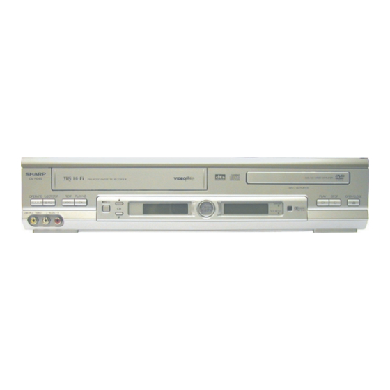
DV-NC65
PAL
OPERATE EJECT/STOP
REW
PLAY/X2
/
REC
VCR/DVD
CH
SELECTOR
LINE IN 3 VIDEO
L - AUDIO - R
DV-NC65H
DV-NC65S
DV-NC70H
PAL
OPERATE EJECT/STOP
REW
PLAY/X2
REC
/
VCR/DVD
CH
SELECTOR
LINE IN 3 VIDEO
L - AUDIO - R
DV-NC70H
1. IMPORTANT SERVICE NOTES ........................................................................................................ 2
2. FEATURES ........................................................................................................................................ 3
3. SPECIFICATIONS ............................................................................................................................. 3
4. PART NAMES .................................................................................................................................... 5
5. MAINTENANCE CHECK ITEMS AND EXECUTION TIME ............................................................. 14
6. DISASSEMBLY METHOD ............................................................................................................... 15
7. OPERATION OF PICKUP ............................................................................................................... 19
8. ADJUSTMENT, REPLACEMENT AND ASSEMBLY OF MECHANICAL UNITS ............................ 20
9. TEST MODE .................................................................................................................................... 43
10. MECHANISM OPERATION FLOWCHART AND TROUBLESHOOTING ....................................... 49
11.TROUBLESHOOTING ...................................................................................................................... 51
12. BLOCK DIAGRAMS ......................................................................................................................... 64
13. SCHEMATIC DIAGRAMS ................................................................................................................ 74
14. PRINTED WIRING BOARD ASSEMBLIES ..................................................................................... 96
15. REPLACEMENT PARTS LIST ...................................................................................................... 113
16. PACKING OF THE SET ................................................................................................................. 132
SERVICE MANUAL
VCR/DVD COMBINATION MODEL
DVD / CD PLAYER
PLAY
STOP
OPEN/CLOSE
TIMER
VCR DVD
DVD / CD PLAYER
PLAY
STOP
OPEN/CLOSE
TIMER
VCR DVD
MODELS
In the interests of user-safety (Required by safety regula-
tions in some countries) the set should be restored to its
original condition and only parts identical to those specified
be used.
CONTENTS
SHARP CORPORATION
1
DV-NC65H/S
DV-NC70H
S92P3DV-NC65H
DV-NC65H
DV-NC65S
DV-NC70H
Page
Advertisement
Table of Contents

Related Manuals for Sharp DV-NC65H


Summary of Contents for Sharp DV-NC65H
-
Page 1: Table Of Contents
DV-NC65H/S DV-NC70H SERVICE MANUAL S92P3DV-NC65H VCR/DVD COMBINATION MODEL DV-NC65 DVD / CD PLAYER OPERATE EJECT/STOP PLAY/X2 PLAY STOP OPEN/CLOSE TIMER VCR/DVD SELECTOR VCR DVD LINE IN 3 VIDEO L - AUDIO - R DV-NC65H DV-NC65S DV-NC65H DV-NC70H DV-NC65S DVD / CD PLAYER... -
Page 2: Important Service Notes
DV-NC65H/S DV-NC70H 1. IMPORTANT SERVICE NOTES • This Unit is classified as a CLASS 1 LASER Note: product. This unit can be used only where the power • The CLASS 1 LASER PRODUCT label is located supply is AC 230V-240V, 50Hz. It cannot be used on the rear cover. -
Page 3: Features
VIDEO jack: RCA Pin-jack AUDIO jack: RCA Pin-jack DVD output jacks VIDEO jack: S-Video jack AUDIO jack: RCA Pin-jack DIGITAL AUDIO IF: Coaxial digital (DV-NC65H/S) : Coaxial digital and Optical digital (DV-NC70H) AUDIO output jack: RCA Pin-jack VIDEO input jacks VIDEO jack: SCART... - Page 4 230 V-240 V AC, 50 Hz Power consumption 21 W W × H × D: 430 mm × 93.5 mm × 350 mm (DV-NC65H/S) Dimensions W × H × D: 430 mm × 93.5 mm × 356 mm (DV-NC70H) Weight 5.3 kg...
-
Page 5: Part Names
DV-NC65H/S DV-NC70H 4. PART NAMES... - Page 6 DV-NC65H/S DV-NC70H...
- Page 7 DV-NC65H/S DV-NC70H...
- Page 8 DV-NC65H/S DV-NC70H...
- Page 9 DV-NC65H/S DV-NC70H...
- Page 10 DV-NC65H/S DV-NC70H...
- Page 11 DV-NC65H/S DV-NC70H...
- Page 12 DV-NC65H/S DV-NC70H...
- Page 13 DV-NC65H/S DV-NC70H...
-
Page 14: Maintenance Check Items And Execution Time
DV-NC65H/S DV-NC70H 5. MAINTENANCE CHECK ITEMS AND EXECUTION TIME MECHANICAL PARTS REGUIRING PERIODICAL INSPECTION Use the following table as a guide to maintain the mechanical parts in good operating condition. Maintained 1,000 hrs. 2,000 hrs. Parts Pickup Spindle Unit Sled Motor... -
Page 15: Disassembly Method
DV-NC65H/S DV-NC70H 6. DISASSEMBLY METHOD 6-1. DISASSEMBLY METHOD 1) Removing the top cabinet. (1) Remove the four screws 1 and the three screws 2. 2) Removing the front panel. (1) Remove the two screws 3. (2) Release the six hooks 4. - Page 16 7) Removing the rear panel/ the antenna terminal cover/ the VCR main PWB unit. (1) Remove the five screws p at rear side. (four screws in DV-NC65H/S) (2) Remove the one screw a for Tuner. (3) Remove the rear panel.
- Page 17 DV-NC65H/S DV-NC70H 6-2. EXTENSION CABLE USE POINT (ONE PLACE) Parts Code Price Code Name/Description QCNW-8571GEZZ Extension cable (wire), 9pin 500mm DVD Main CN3201–Power CN201 Extension Cable Diagram Tuner QCNW-8571GEZZ 9 pin Power PWB DVD Mechanism CN201 VCR Main PWB VCR Mechanism...
- Page 18 DV-NC65H/S DV-NC70H 6-3. REPLACEMENT OF MAIN PARTS <Take out disk> 1. Remove the mechanism with angle from the set. (refer to 33 on page 130. Remove K , M , N ) 2. It is in such cases as the thin driver, and it is pushed in slowly, and a tray is drawn in the arrow direction the Slide Rack on the left of the base chassis.
-
Page 19: Operation Of Pickup
DV-NC65H/S DV-NC70H 7. OPERATION OF PICKUP 7-1. CIRCUIT CONFIGURATION OF PICKUP The pickup unit reads signals from the disk, and the flexible cable is connected to the board. The following signals flow through the cable. 7-3. POLARITIES OF SIGNAL 7-2. EQUIVALENT CIRCUIT OF PICKUP... -
Page 20: Adjustment, Replacement And Assembly Of Mechanical Units
DV-NC65H/S DV-NC70H 8. ADJUSTMENT, REPLACEMENT AND ASSEMBLY OF MECHANICAL UNITS The explanation given below relates to the on-site general service (field service) but it does not relates to the adjustment and replacement which need high-grade equipment, jigs and skill. For example, the drum assembling, replacement and adjustment service must be performed by the person who have finished the technical courses. - Page 21 DV-NC65H/S DV-NC70H 8-2. MAINTENANCE CHECK ITEMS AND EXECUTION TIME Perform the maintenance with the regular intervals as follows so as to maintain the quality of machine. Maintained 1000 1500 2000 Possible symptom Remarks encountered hrs. hrs. hrs. hrs. Parts Abnormal rotation or significant Guide roller ass’y...
- Page 22 DV-NC65H/S DV-NC70H 8-3. FUNCTION OF MAJOR MECHANICAL PARTS (TOP VIEW) Function Function Full erase head Reverse guide lever ass’y Supply pole base ass’y Reel relay gear Tension arm ass'y Take-up reel disk Idler wheel ass’y Pinch roller lever ass’y Open guide...
- Page 23 DV-NC65H/S DV-NC70H FUNCTION OF MAJOR MECHANICAL PARTS (BOTTOM VIEW) Function Function Syncro Gear Clutch lever Master cam Limitter pulley ass’y Capstan D.D. motor Shifter Reel belt...
- Page 24 DV-NC65H/S DV-NC70H 8-4. DISASSEMBLY AND REASSEMBLY 8-4-1. DISASSEMBLING THE MECHANISM 2. Removing the mechanism and cassette housing. 1. When removing the mechanism from the set. Remove the two screws 2 fixing the cassette housing Remove the two screws 1 which connecting mechanism to the mechanism, and remove the cassette housing.
- Page 25 DV-NC65H/S DV-NC70H 2. Mechanical initial setting • After confirming that the mechanism is returned to the • When performing the initial setting manually, press and initial setting position, mount the cassette housing to the turn the flange of the worm as shown in the figure below.
- Page 26 DV-NC65H/S DV-NC70H 8-5. REMOVING AND INSTALLING THE CA- *1: The hole of the pinch drive cam must be directed toward the synchro gear shaft. SSETTE HOUSING *2: The long hole of the master cam must be located on • Removal the front side.
- Page 27 DV-NC65H/S DV-NC70H • Height checking and adjustment 8-7. REEL DISK REPLACEMENT AND HEIGHT 1. Set the master plane with due care so that it does not CHECK contact the drum. • Removal 2. When putting the master plane, shift the reverse guide 1.
- Page 28 DV-NC65H/S DV-NC70H 8-9. CHECKING AND ADJUSTMENT OF TAKE- 8-8. CHECKING AND ADJUSTMENT OF TAKE- UP TORQUE IN FAST FORWARD MODE UP TORQUE IN REWIND MODE • Remove the cassette housing control assembly. • Remove the cassette housing control assembly. • After short-circuiting between TP803 and TP802 pro- •...
- Page 29 DV-NC65H/S DV-NC70H 8-10. CHECKING AND ADJUSTMENT OF TAKE- 8-11. CHECKING AND ADJUSTMENT OF TAKE- UP TORQUE IN RECORD/PLAYBACK UP TORQUE IN VIDEO SEARCH REWIND MODE MODE • Load the cassette torque meter into the unit. • Remove the cassette housing control assembly.
- Page 30 DV-NC65H/S DV-NC70H 8-12. CHECKING THE VIDEO SEARCH REWIND BACK TENSION • Remove the cassette housing control assembly. • After short-circuiting between TP803 and TP802 pro- vided at VCR Operation PWB, plug in the power cord. Tension gauge Pinch roller 900 - 1,200gf •...
- Page 31 DV-NC65H/S DV-NC70H • Checking Tension pole adjustment driver adjusting direction 1. Set a cassette tape, push the REC button to place the unit in the SP record mode. Now check the tension pole position. 2. Visually check to see if the position of the tension pole is +0.5...
- Page 32 DV-NC65H/S DV-NC70H • Checking the brake torque at the take-up side • Adjustment 1. If the indication of torque cassette meter is lower than the setting, shift the tension spring engagement to the part A. Torque gauge 2. If the indication of torque cassette meter is higher than the setting, shift the tension spring engagement to the part B.
- Page 33 DV-NC65H/S DV-NC70H 3. Align the left end of gear of A/C head plate with the 8-17. REPLACEMENT OF A/C HEAD punched mark of chassis, tentatively tighten the screws 1. In eject position unplug the power cord. 1 so as to ensure smooth motion of A/C head plate.
- Page 34 DV-NC65H/S DV-NC70H 8-19. ADJUSTMENT OF TAPE DRIVE TRAIN 8-18. A/C HEAD HEIGHT ROUGH ADJUSTMENT • Setting 1. Tape run rough adjustment 1 Check and adjust the position of the tension pole. (See 8-14.) Azimuth screw 2 Check and adjust the video search rewind back tension.
- Page 35 DV-NC65H/S DV-NC70H 3 Next, press the tracking button (+), (–) and change Notes: 1. Previously set the tracking control in the center position, the ATR signal waveform from max to min and from and adjust the ATR signal waveform to maximum with X min to max.
- Page 36 DV-NC65H/S DV-NC70H When the tape is above the helical lead. When the tape is below the helical lead. Supply side Take-up side Supply side Take-up side Supply side guide roller Take-up side guide roller Supply side guide roller Take-up side guide roller...
- Page 37 DV-NC65H/S DV-NC70H 8-20. REPLACEMENT OF THE CAPSTAN D.D. 8-21. REPLACEMENT OF DRUM D.D. MOTOR (DIRECT DRIVE) MOTOR 1. Set the ejection mode. 2. Withdraw the main power plug from the socket. • Remove the mechanism from the set. • Removal (Perform in numerical order.) •...
- Page 38 DV-NC65H/S DV-NC70H 8-22. REPLACING THE UPPER AND LOWER 8-23. ASSEMBLING OF PHASE MATCHING DRUM ASSEMBLY MECHANISM COMPONENTS • Replacement (Perform in the numerical order) • Assemble the phase matching mechanism compo- 1 Remove the motor as stated in 8-21 Replacement of nents in the following order.
- Page 39 DV-NC65H/S DV-NC70H 8-24. INSTALLING THE SIFTER * Remove the SUP/TU main brake before installation. Drum 1. Make sure that the loading arm T and S are at the Phase- Matching point as shown below 2. Fix the sifter position setting part to the roading arm T Capstan D.D.
- Page 40 DV-NC65H/S DV-NC70H 8-26. REPLACEMENT OF LOADING MOTOR 8-25. INSTALLING THE MASTER CAM (AT REAR • Removal SIDE OF MECHANISM CHASSIS) 1. Before installing the master cam, make sure that the sifter is at initial position. (Right side from bottom view) 2.
- Page 41 DV-NC65H/S DV-NC70H 8-27. ASSEMBLY OF CASSETTE HOUSING 1. Proof lever, Proof lever spring and Holder R MSPRD0215AJFJ *Proof lever spring fixing direction designated. Figure 8-42. 2. Open lever, Sensor Plate and Drive Lever to Frame R Outer Outside Inner Bottom...
- Page 42 DV-NC65H/S DV-NC70H 4. Frame R, Frame L, Drive Arm R, Drive Arm L, Upper Plate. LANGF9661AJFW Top surface should be free from scratches or soil. When assemble drive lever to frame R (on the back side), make sure the hole synchronize.
-
Page 43: Test Mode
DV-NC65H/S DV-NC70H 9. TEST MODE "NO DISC" state "F0" Key input (Press "Play" Key and "Stop" Key for 5 seconds.) F0000000 00000000 <Press "1" Key on the remote control or "Stop" Key on the main unit.> 10000000 ~~~~~~~~ The preparation date... - Page 44 DV-NC65H/S DV-NC70H From (1) Step execution mode "2" Key input STEP TEST Load a disc after the tray is opened. TRAY OPEN "Playback" Key input STEP TEST FOCUS ON Focus on ASMAX ~~~~ ENVPP ~~~~ ~~~~ FEPP "Playback" Key input...
- Page 45 DV-NC65H/S DV-NC70H From (2) Spin offset adjustment mode "DVD Menu" Key input SPIN OFFSET ADJUST The tray opens. SPIN OFFSET ADJUST (Offset adjustment of the spindle is executed automatically.) ADJUST COMPLETE The adjustment result is indicated in the ~~~~ section.
- Page 46 DV-NC65H/S DV-NC70H REPLACEMENT OF IC710 (E PROM) <<Servicing precautions>> When the IC710 (E PROM) has replaced, make the following reprogramming. Depending on models, the IC710 (E PROM) has been factory adjusted for its memory function. It's therefore necessary to reprogram the memory function for the model in question.
- Page 47 DV-NC65H/S DV-NC70H 4. Jumper setting of JP0 to JP39 in hexadecimal notation and REC current setting. a. Check the power on. (Power is ON.) b. Make short-circuit test point (TP801 and TP803) and hold the point. Be sure that all the VCR LCD displays light up into the TEST mode.
- Page 48 DV-NC65H/S DV-NC70H PROM MAP Jumper Model Name DV-NC65S DV-NC65H DV-NC70H Jumper Name Colour0 Colour1 VPS/PDC Low power X400 FF/REW System0 System1 Tuner0 Tuner1 JP10 Tuner2 JP11 RF_out_set_off JP12 Dual scart JP13 Front AV JP14 JP15 JP16 G-CODE0 JP17 G-CODE1 JP18...
- Page 49 DV-NC65H/S DV-NC70H...
- Page 50 DV-NC65H/S DV-NC70H...
- Page 51 DV-NC65H/S DV-NC70H...
- Page 52 DV-NC65H/S DV-NC70H...
- Page 53 DV-NC65H/S DV-NC70H...
- Page 54 DV-NC65H/S DV-NC70H...
- Page 55 DV-NC65H/S DV-NC70H...
- Page 56 DV-NC65H/S DV-NC70H...
- Page 57 DV-NC65H/S DV-NC70H...
- Page 58 DV-NC65H/S DV-NC70H...
- Page 59 DV-NC65H/S DV-NC70H...
- Page 60 DV-NC65H/S DV-NC70H...
- Page 61 DV-NC65H/S DV-NC70H...
- Page 62 DV-NC65H/S DV-NC70H...
- Page 63 DV-NC65H/S DV-NC70H - M E M O -...
-
Page 64: Block Diagrams
DV-NC65H/S DV-NC65H/S DV-NC70H DV-NC70H 12. BLOCK DIAGRAMS 12-1. MAIN BLOCK DIAGRAM 64~65... - Page 65 DV-NC65H/S DV-NC65H/S DV-NC70H DV-NC70H 12-2. VCR SIGNAL FLOW BLOCK DIAGRAM 66~67...
- Page 66 DV-NC65H/S DV-NC65H/S DV-NC70H DV-NC70H 12-3. VCR SERVO BLOCK DIAGRAM 68~69...
- Page 67 DV-NC65H/S DV-NC65H/S DV-NC70H DV-NC70H 12-4. AUDIO BLOCK DIAGRAM 70~71...
- Page 68 DV-NC65H/S DV-NC65H/S DV-NC70H DV-NC70H 12-5. POWER BLOCK DIAGRAM 72~73...
-
Page 69: Schematic Diagrams
DV-NC65H/S DV-NC65H/S DV-NC70H DV-NC70H 13. SCHEMATIC DIAGRAMS 13-1. DVD MAIN (1) CIRCUIT SCHEMATIC DIAGRAM 74~75... - Page 70 DV-NC65H/S DV-NC65H/S DV-NC70H DV-NC70H 13-2. DVD MAIN (2) CIRCUIT SCHEMATIC DIAGRAM 76~77...
- Page 71 DV-NC65H/S DV-NC65H/S DV-NC70H DV-NC70H 13-3. VCR MAIN (1) CIRCUIT SCHEMATIC DIAGRAM (DV-NC65H/70H) 78~79...
- Page 72 DV-NC65H/S DV-NC65H/S DV-NC70H DV-NC70H 13-4. VCR MAIN (1) CIRCUIT SCHEMATIC DIAGRAM (DV-NC65S) 80~81...
- Page 73 DV-NC65H/S DV-NC65H/S DV-NC70H DV-NC70H å AND SHADED COMPONENTS=SAFETY RELATED PARTS 13-5. VCR MAIN (2) CIRCUIT SCHEMATIC DIAGRAM (DV-NC65H/70H) å 82~83...
- Page 74 DV-NC65H/S DV-NC65H/S DV-NC70H DV-NC70H å AND SHADED COMPONENTS=SAFETY RELATED PARTS 13-6. VCR MAIN (2) CIRCUIT SCHEMATIC DIAGRAM (DV-NC65S) å 84~85...
- Page 75 DV-NC65H/S DV-NC65H/S DV-NC70H DV-NC70H å AND SHADED COMPONENTS=SAFETY RELATED PARTS 13-7. VCR MAIN (3) CIRCUIT SCHEMATIC DIAGRAM (DV-NC65H/70H) 86~87...
- Page 76 DV-NC65H/S DV-NC65H/S DV-NC70H DV-NC70H 13-8. VCR MAIN (3) CIRCUIT SCHEMATIC DIAGRAM (DV-NC65S) 88~89...
- Page 77 DV-NC65H/S DV-NC65H/S DV-NC70H DV-NC70H 13-9. TERMINAL CIRCUIT SCHEMATIC DIAGRAM 90~91...
- Page 78 DV-NC65H/S DV-NC70H 13-10. DVD OPERATION CIRCUIT SCHEMATIC DIAGRAM...
- Page 79 DV-NC65H/S DV-NC70H 13-11. VCR OPERATION CIRCUIT SCHEMATIC DIAGRAM...
- Page 80 DV-NC65H/S DV-NC65H/S DV-NC70H DV-NC70H å AND SHADED COMPONENTS=SAFETY RELATED PARTS 13-12. POWER CIRCUIT SCHEMATIC DIAGRAM 94~95...
- Page 81 DV-NC65H/S DV-NC65H/S DV-NC70H DV-NC70H 14. PRINTED WIRING BOARD ASSEMBLIES DVD MAIN PWB SIDE A T P3 2 0 6 T P3 2 0 7 T P3 2 0 8 R3 2 1 8 CN3 3 0 1 Q3 2 0 4...
- Page 82 DV-NC65H/S DV-NC65H/S DV-NC70H DV-NC70H DVD MAIN PWB SIDE B RJ 3 1 0 6 R3 8 0 3 C3 8 0 6 R3 3 0 1 R3 3 0 2 Q3 3 0 1 R3 8 0 1 R3 3 0 3...
- Page 83 DV-NC65H/S DV-NC65H/S DV-NC70H DV-NC70H VCR MAIN PWB SIDE A Symbol 100~101...
- Page 84 DV-NC65H/S DV-NC65H/S DV-NC70H DV-NC70H VCR MAIN PWB SIDE B 102~103...
- Page 85 DV-NC65H/S DV-NC70H TERMINAL PWB SIDE A Symbol...
- Page 86 DV-NC65H/S DV-NC70H TERMINAL PWB SIDE B...
- Page 87 DV-NC65H/S DV-NC70H DVD OPERATION PWB SIDE A Symbol SIDE B...
- Page 88 DV-NC65H/S DV-NC70H VCR OPERATION PWB SIDE A Symbol SIDE B...
- Page 89 DV-NC65H/S DV-NC65H/S DV-NC70H DV-NC70H POWER PWB SIDE A Symbol 108~109...
- Page 90 DV-NC65H/S DV-NC65H/S DV-NC70H DV-NC70H POWER PWB SIDE B 110~111...
- Page 91 DV-NC65H/S DV-NC70H - M E M O -...
-
Page 92: Printed Wiring Board Assemblies
DV-NC65H/S DV-NC70H 15. REPLACEMENT PARTS LIST/ Ref. No. Part No. Description Code Ref. No. Part No. Description Code EXPLODED VIEWS Q3502 VSDTC124EUA-1Y V DTC124EUA DIODES ELECTRICAL PARTS LIST D3301 VHDDAP222//-1Y V DAP222 D3501 VHDDAN222//-1Y V DAN222 Parts marked with " å " are important for maintaining the safety of the set. - Page 93 DV-NC65H/S DV-NC70H Ref. No. Part No. Description Code Ref. No. Part No. Description Code DUNTKB209TE6H C3741 VCKYCY1CB104KY V 0.1 16V Ceramic DVD MAIN PWB UNIT(Continued) C3742 VCKYCY1CB104KY V 0.1 16V Ceramic C3743 VCKYCY1CB104KY V 0.1 16V Ceramic C3613 VCKYCY1CB104KY V 0.1 16V Ceramic C3744 VCKYCY1CB104KY V 0.1...
- Page 94 DV-NC65H/S DV-NC70H Ref. No. Part No. Description Code Ref. No. Part No. Description Code DUNTKB209TE6H R3627 VRS-CY1JF820JY V 82 1/16W Metal Oxide AA DVD MAIN PWB UNIT(Continued) R3628 VRS-CY1JF820JY V 82 1/16W Metal Oxide AA R3629 VRS-CY1JF820JY V 82 1/16W Metal Oxide AA...
- Page 95 DV-NC65H/S DV-NC70H Ref. No. Part No. Description Code Ref. No. Part No. Description Code DUNTKB209TE6H Q401 VSKRC102S//-1Y V KRC102S DVD MAIN PWB UNIT(Continued) Q402 VS2SK1826++-1Y V 2SK1826++ Q403 VSKRC102S//-1Y V KRC102S FB3505 RBLN-0077TAZZY V Balun, BLN-0077TA Q501 VS2PD601AR/-1Y V 2PD601AR...
- Page 96 DV-NC65H/S DV-NC70H Ref. No. Part No. Description Code Ref. No. Part No. Description Code DUNTKB210TEV4(NC70H) C304 VCKYCY1HF103ZS V 0.01 50V Ceramic DUNTKB210TEV5(NC65H) C305 VCKYCY1HF103ZS V 0.01 50V Ceramic DUNTKB210TEV7(NC65S) C306 VCKYCY1HF103ZS V 0.01 50V Ceramic VCR MAIN PWB UNIT(Continued) C307 VCKYCY1HF103ZS V 0.01...
- Page 97 DV-NC65H/S DV-NC70H Ref. No. Part No. Description Code Ref. No. Part No. Description Code DUNTKB210TEV4(NC70H) C798 VCEAKM1CW476M+ V 47 16V Electrolytic DUNTKB210TEV5(NC65H) C801 VCCCCY1HH470JS V 47p 50V Ceramic DUNTKB210TEV7(NC65S) C802 VCCCCY1HH470JS V 47p 50V Ceramic C822 VCEA9A1CW106M+ V 10 16V Electrolytic...
- Page 98 DV-NC65H/S DV-NC70H Ref. No. Part No. Description Code Ref. No. Part No. Description Code DUNTKB210TEV4(NC70H) R702 VRD-RA2BE102JY V 1k 1/8W Carbon DUNTKB210TEV5(NC65H) R704 VRS-CY1JF153JS V 15k 1/16W Metal Oxide AA DUNTKB210TEV7(NC65S) R705 VRS-CY1JF153JS V 15k 1/16W Metal Oxide AA VCR MAIN PWB UNIT(Continued)
- Page 99 DV-NC65H/S DV-NC70H Ref. No. Part No. Description Code Ref. No. Part No. Description Code DUNTKB210TEV4(NC70H) R7717 VRS-CY1JF101JS V 100 1/16W Metal Oxide AA DUNTKB210TEV5(NC65H) R7721 VRS-CY1JF101JS V 100 1/16W Metal Oxide AA DUNTKB210TEV7(NC65S) R7722 VRS-CY1JF101JS V 100 1/16W Metal Oxide AA...
- Page 100 DV-NC65H/S DV-NC70H Ref. No. Part No. Description Code Ref. No. Part No. Description Code DUNTKB372TEV1 C1804 VCEA9M1HW475M+ V 4.7 50V Electrolytic TERMINAL PWB UNIT(Continued) C1805 VCEA9A1HW105M+ V 1 50V Electrolytic C1806 VCEA9M1HW105M+ V 1 50V Electrolytic Q2305 VSKRA102S//-1Y V KRA102S C1807 VCKYD41CY103NY V 0.01...
- Page 101 DV-NC65H/S DV-NC70H Ref. No. Part No. Description Code Ref. No. Part No. Description Code DUNTKB372TEV1 R2901 VRD-RA2EE331JY U 330 1/4W Carbon TERMINAL PWB UNIT(Continued) R2903 VRD-RA2BE183JY V 18k 1/8W Carbon R2904 VRS-CY1JF153JY V 15k 1/16W Metal Oxide AA VRS-CY1JF000JY 1/16W Metal Oxide AA...
- Page 102 DV-NC65H/S DV-NC70H Ref. No. Part No. Description Code Ref. No. Part No. Description Code DUNTKB374TEV1 MISCELLANEOUS PARTS DVD OPERATION PWB UNIT(Continued) CN8001 QSOCN0895REZZ V Socket, 8Pin J8001 QJAKE0190CEZZ V Jack, 3Pin C8055 VCKYCY1HF103ZY V 0.01 50V Ceramic J8002 QJAKE0257GEZZ V Jack, 3Pin...
- Page 103 DV-NC65H/S DV-NC70H Ref. No. Part No. Description Code Ref. No. Part No. Description Code DUNTKB376TEV1 MISCELLANEOUS PARTS POWER PWB UNIT(Continued) CN201 QPLGN0978GEZZ V Plug, 9Pin å F901 QFS-C2025CEZZ V Fuse, 250V/2A å C915 RC-KZ0102GEZZ V 680p 250V Ceramic å FH901 QFSHD1017CEZZ+ V Fuse Holder...
- Page 104 DV-NC65H/S DV-NC70H Ref. No. Part No. Description Code Ref. No. Part No. Description Code MECHANISM PARTS (VCR PART) LX-HZ3082GEZZ V Screw WSW 2.6+6(AC) XJPSD26P06000 V Screw 2.6+6S(CAPST), x3 LX-RZ3015GEFJ V CS Washer, x2 LBNDK1021AJZZ V Tension Band Ass'y XRESJ30-06000 V E-Ring(E-3)
- Page 105 DV-NC65H/S DV-NC70H Ref. No. Part No. Description Code Ref. No. Part No. Description Code CABINET PARTS FRONT PANEL PARTS CCABAA093TEV1 U Top Cabinet Ass'y CPNLCA044TEV1 U Front Panel Ass'y TLABM0167UMZZ U Model Label (NC70H) DUNTKB372TEV1 – Terminal PWB Unit —...
- Page 106 DV-NC65H/S DV-NC70H Ref. No. MECHANISM EXPLODED VIEW (DVD PART) Part No. Description Code Ref. No. Part No. Description Code Dry Coating Dry Coating Dry Coating Dry Coating Grease Grease 401-11 401-13 401-10 Grease 401-12 Grease 401-4 401-3 401-2 Grease 401-5 401-9 å...
- Page 107 DV-NC65H/S DV-NC70H Ref. No. Part No. Description Code Ref. No. Part No. Description Code MECHANISM EXPLODED VIEW (VCR PART) Grease...
- Page 108 DV-NC65H/S DV-NC70H Ref. No. Part No. Description Code Ref. No. Part No. Description Code CASSETTE HOUSING CONTROL EXPLODED VIEW Grease...
- Page 109 DV-NC65H/S DV-NC70H Ref. No. CABINET EXPLODED VIEW Part No. Description Code Ref. No. Part No. Description Code...
- Page 110 DV-NC65H/S DV-NC70H Ref. No. FRONT PANEL EXPLODED VIEW Part No. Description Code Ref. No. Part No. Description Code 600-13 600-6 600-A 600-3 600-11 600-14 600-4 600-1 600-5 600-2 600-12 600-9 600-10 600-8 600-7...
-
Page 111: Packing Of The Set
DV-NC70H Ref. No. Part No. Description Code Ref. No. Part No. Description Code 16. PACKING OF THE SET TiNS-A220WJZZ (DV-NC70H) TiNS-A221WJZZ (DV-NC70H) TiNS-A222WJZZ (DV-NC65H) TiNS-A223WJZZ (DV-NC65H) RRMCGA054WJSA TiNS-A268WJZZ (DV-NC65S) (DV-NC70H) TiNS-A269WJZZ (DV-NC65S) RRMCGA055WJSA (Operation Manual) (DV-NC65S) RRMCGA069WJSA # TGAN-3170UMZZ (DV-NC65H) - Page 112 DV-NC65H/S DV-NC70H Ref. No. Part No. Description Code Ref. No. Part No. Description Code...
- Page 113 Part No. Description Code © COPYRIGHT 2002 BY SHARP CORPORATION ALL RIGHTS RESERVED. No part of this publication may be reproduced, stored in a retrieval system, or transmitted in any form or by any means, electronic, mechanical, photocopying, recording, or otherwise, without prior written permission of the publisher.