Table of Contents
Advertisement
Quick Links
2E42-27/2E42-27R/2E43-27/2E43-27R
PWR
CPU
RESET
2E42-27
COM
PWR
CPU
RESET
2E43-27
COM
9031960-05
SmartSwitch 2200
User's Guide
2
4
6
8
10
12
1
3
5
7
9
11
1X
3X
5X
7X
9X
11X
2
4
6
8
10
12
1
3
5
7
9
11
14
16
18
20
22
24
13
15
17
19
21
23
13X
15X
17X
19X
21X
23X
20
16
18
22
24
14
19
21
13
15
17
23
25
26
25
26
Advertisement
Table of Contents
Troubleshooting

Related Manuals for Cabletron Systems 2E42-27


Summary of Contents for Cabletron Systems 2E42-27
- Page 1 2E42-27/2E42-27R/2E43-27/2E43-27R SmartSwitch 2200 RESET 2E42-27 RESET 2E43-27 9031960-05 User’s Guide...
-
Page 3: Smartswitch
Only qualified personnel should perform installation procedures. Cabletron Systems reserves the right to make changes in specifications and other information contained in this document without prior notice. The reader should in all cases consult Cabletron Systems to determine whether any such changes have been made. -
Page 4: Industry Canada Notice
IMPORTANT: Before utilizing this product, carefully read this License Agreement. This document is an agreement between you, the end user, and Cabletron Systems, Inc. (“Cabletron”) that sets forth your rights and obligations with respect to the Cabletron software program (the “Program”) contained in this package. - Page 5 Government is subject to restrictions as set forth in subparagraph (c) (1) (ii) of the Rights in Technical Data and Computer Software clause at 252.227-7013. Cabletron Systems, Inc., 35 Industrial Way, Rochester, New Hampshire 03867-0505. 2E42-27/2E42-27R/2E43-27/2E43-27R User’s Guide...
-
Page 6: Safety Information
Do not use optical instruments to view the laser output. The use of optical instruments to view laser output increases eye hazard. When viewing the output optical port, power must be removed from the network adapter. 2E42-27/2E42-27R/2E43-27/2E43-27R User’s Guide SAFETY INFORMATION SAFETY INFORMATION... -
Page 7: Declaration Of Conformity
Mr. Ronald Fotino ___________________________________ Full Name Principal Compliance Engineer ___________________________________ Title Rochester, NH, USA ___________________________________ Location 2E42-27/2E42-27R/2E43-27/2E43-27R User’s Guide 89/336/EEC 73/23/EEC Cabletron Systems, Inc. 35 Industrial Way PO Box 5005 Rochester, NH 03867 Mr. J. Solari Cabletron Systems Limited Nexus House, Newbury Business Park... - Page 8 Notice 2E42-27/2E42-27R/2E43-27/2E43-27R User’s Guide...
-
Page 9: Table Of Contents
Installing the 2E4X-27 ... 3-3 3.3.1 Tabletop or Shelf Installation ... 3-3 3.3.2 Rackmount Installation ... 3-4 3.3.3 Connecting Power to the 2E42-27 or 2E43-27 ... 3-7 3.3.4 Connecting Power to the 2E42-27R or 2E43-27R ... 3-8 2E42-27/2E42-27R/2E43-27/2E43-27R User’s Guide CONTENTS... - Page 10 5.7.9 Setting the Operational Mode...5-25 5.7.10 Configuring the COM Port ...5-26 5.7.10.1 Changing the Com Port Application...5-28 5.7.11 Clearing NVRAM ...5-29 5.7.12 Enabling/Disabling IP Fragmentation ...5-30 viii 2E42-27/2E42-27R/2E43-27/2E43-27R User’s Guide 2E42-27 or 2E42-27R Cable Connections...3-10 2E43-27 or 2E43-27R Cable Connections...3-11...
- Page 11 5.12 Device Specific Configuration Menu Screen ... 5-42 5.13 System Resources Screen ... 5-44 5.13.1 Setting the Reset Peak Switch Utilization ... 5-46 5.14 High Speed Interface Configuration Menu Screen ... 5-46 5.15 High Speed Interface Configuration Screen ... 5-48 5.15.1 Configuring an FE-100FX or FE-100F3...
- Page 12 FE-100F3 ... B-3 APPENDIX C OPTIONAL INSTALLATIONS AND MODE SWITCH BANK SETTINGS Required Tools... C-2 Removing the Chassis Cover ... C-2 C.2.1 Setting the Mode Switch ... C-4 Installing Optional Fast Ethernet Interface Modules ... C-7 INDEX 2E42-27/2E42-27R/2E43-27/2E43-27R User’s Guide...
-
Page 13: Chapter 1 Introduction
Welcome to the 2E42-27/2E42-27R/2E43-27/2E43-27R SmartSwitch 2200 User’s Guide. This guide describes the 2E42-27, 2E42-27R, 2E43-27, and 2E43-27R SmartSwitch 2200 devices and provides information concerning network requirements, installation, troubleshooting, and the use of Local Management. USING THIS GUIDE Read through this guide completely to understand the 2E42-27, 2E42-27R, 2E43-27, and 2E43-27R features, capabilities, and Local Management functions. -
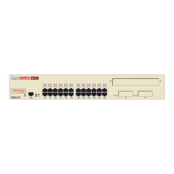
Page 14: 2E4X-27 Features
Optional Installations and Mode Switch Bank describes how to install optional Fast Ethernet Interface Modules and how to set the Mode Switch. 2E4X-27 FEATURES Figure 1-1 shows the 2E42-27 and 2E43-27. Following the figure is a list of the features. RESET 2E42-27 Port Status LEDs... - Page 15 • SmartTrunk, which allows the user to logically group interfaces on the 2E4X-27 via Local Management to provide a higher aggregate bandwidth between Cabletron Systems devices that support the SmartTrunk feature. • Runtime IP Address Discovery, which allows the 2E4X-27 to send out Reverse Address Resolution (RARP) and Bootstrap Protocol (BootP) requests to determine its Internet Protocol (IP) address.
-
Page 16: 2E4X-27 Overview
The 2E4X-27 is a tabletop unit that can be installed in a standard 19-inch rack using the supplied rack mounting hardware. The 2E42-27 and 2E43-27 have one universal ac power supply with automatic voltage sensing that allows operation using 100–125 or 200–240 Vac, 50/60 Hz. -
Page 17: Full Duplex Switched Ethernet
All purchased bandwidth is used. • Distributed, resilient links increase reliability and performance. • Multiple technologies are supported within a single trunk for maximum flexibility. For more information about SmartTrunk, refer to the Cabletron Systems SmartTrunk User’s Guide. 2E42-27/2E42-27R/2E43-27/2E43-27R User’s Guide 2E4X-27 Overview... -
Page 18: Runtime Ip Address Discovery
IP Address Discovery (RAD) checks the 2E42-27 for an IP address. If one has not yet been assigned (2E42-27 IP address set to 0.0.0.0), RAD checks to see if any of the 2E42-27 interfaces have a link. If so, RAD sends out Reverse Address Resolution Protocol (RARP) and BootP requests to obtain an IP address from a BootP server on the network. -
Page 19: Switching Options
MIBs including RFC 1213 (MIB II), RFC 1757 (RMON), RFC 1371 (RS232 MIB), RFC 1493 (Bridge MIB) and RFC 1354 (FIB MIB). A full suite of Cabletron Systems Enterprise MIBs provide a wide array of statistical information to enhance troubleshooting. -
Page 20: Optional Features
Options for the 2E4X-27 include Fast Ethernet Interface Modules and High Speed Interface Modules to add additional interface capability. Cabletron Systems provides Fast Ethernet Interface Modules to support uplinks to 100 Mbps Ethernet backbones or high speed connections to local servers. The Fast Ethernet Interface Modules are listed in... -
Page 21: Document Conventions
Electrical Hazard Warning symbol. Warns against an action that could result in personal injury or death due to an electrical hazard. Warning symbol. Warns against an action that could result in personal injury or death. WARNING 2E42-27/2E42-27R/2E43-27/2E43-27R User’s Guide Document Conventions... -
Page 22: Getting Help
Cabletron Systems Technical Writing Department via the following email address: TechWriting@cabletron.com Make sure to include the document Part Number in the email message. Before calling the Cabletron Systems Global Call Center, have the following information ready: • Your Cabletron Systems service contract number •... -
Page 23: Related Manuals
These manuals can be obtained from the World Wide Web in Adobe Acrobat Portable Document Format (PDF) at the following site: http://www.cabletron.com/ All documentation for the Cabletron Systems SecureFast VLAN NOTE Manager software is contained on the VLAN Manager CD-ROM. - Page 24 Chapter 1: Introduction 1-12 2E42-27/2E42-27R/2E43-27/2E43-27R User’s Guide...
-
Page 25: Chapter 2 Network Requirements
The network installation must meet the guidelines to ensure satisfactory performance of this equipment. Failure to follow the guidelines may produce poor network performance. The Cabletron Systems Cabling Guide and SmartTrunk User’s NOTE Guide , referred to in the following sections can be found on the Cabletron Systems World Wide Web site: http://www.cabletron.com/... -
Page 26: 100Base-Tx Network
100BASE-FX FIBER OPTIC NETWORK Ports 25 and 26 of the 2E4X-27 support the Cabletron Systems FE-100FX and FE-100F3 fiber optic interface modules. The device at the other end of the fiber optic segment must meet the 100BASE-FX Fast Ethernet network requirements to operate at 100 Mbps. -
Page 27: Chapter 3 Installation
Installing Options • Installing the 2E4X-27 (on a shelf or tabletop, or into a standard rack) (Section 3.3) • Connecting to the Network • Completing the Installation 2E42-27/2E42-27R/2E43-27/2E43-27R User’s Guide CHAPTER 3 INSTALLATION (Section 3.1) (Section 3.2) (Section 3.4) (Section... -
Page 28: Unpacking The 2E4X-27
Remove the black and yellow tape seal on the non-conductive bag to remove the 2E4X-27. Perform a visual inspection of the device for any signs of physical damage, and contact the Cabletron Systems Global Call Center if there are any signs of damage. Refer to details. -
Page 29: Installing The 2E4X-27
To ensure proper ventilation and prevent overheating, leave a minimum clearance space of 5.1 cm (2.0 in) at the left, right, CAUTION and rear of the 2E4X-27. 2E42-27/2E42-27R/2E43-27/2E43-27R User’s Guide Section 3.3.3 for 2E42-27/ 2E43-27 power Section 3.3.4 for 2E42-27R/2E43-27R Installing the 2E4X-27 Section 3.3.2... -
Page 30: Rackmount Installation
Figure 3-1 Tabletop or Shelf Installation 3.3.2 Rackmount Installation To install the 2E4X-27 in a 19-inch rack, Cabletron Systems includes an accessory kit containing the rackmount brackets, mounting screws, and a strain-relief bracket for cable management. Guidelines for the Rackmount Installation... - Page 31 2E4X-27. Use of longer screws may damage the unit or cause electrical shock. Attach the strain-relief bracket to the bottom of the 2E4X-27 using the four 8-32 x 3/8-inch pan-head screws Strain-Relief Bracket Figure 3-2 Attaching the Strain-Relief Bracket 2E42-27/2E42-27R/2E43-27/2E43-27R User’s Guide (Figure Screws (4) Installing the 2E4X-27 3-2). 2E42-27...
- Page 32 With the mounting brackets installed, position the 2E4X-27 between the vertical frame members of the 19-inch rack and fasten it securely with mounting screws as shown in RESET 2E42-27 Figure 3-4 Installing the 2E4X-27 in a Rack 2E42-27/2E42-27R/2E43-27/2E43-27R User’s Guide Figure 3-3. Rackmount Brackets (2) Screws (4) Figure...
-
Page 33: Connecting Power To The 2E42-27 Or 2E43-27
100–125 Vac or 200–250 Vac, 50/60 Hz. To connect the 2E42-27 or 2E43-27 to a power source, proceed as follows: Plug the power cord into a grounded wall outlet. The POWER LED turns ON (green) and the CPU LED turns ON (green) briefly. -
Page 34: Connecting Power To The 2E42-27R Or 2E43-27R
Check the power cord connections and the power source. If there are no problems with the power cord connections or power source and the CPU LED is still not green, contact the Cabletron Systems Global Call Center. Refer to Section 1.6 for details. -
Page 35: Connecting To The Network
SmartTrunk User’s Guide for the configuration information. Ports 1 through 24 on the 2E42-27 and 2E42-27R have RJ45 connectors for UTP connections. Ports 1 through 24 on the 2E43-27 and 2E43-27R have two RJ21 connectors for UTP connections. On all of these devices, ports 25 and 26 support FE-100TX, FE-100FX, or FE-100F3 Fast Ethernet Interface Modules. -
Page 36: 2E42-27 Or 2E42-27R Cable Connections
Chapter 3: Installation 3.4.1.1 2E42-27 or 2E42-27R Cable Connections Ports 1 through 24 of the 2E42-27 or 2E42-27R are 10BASE-T ports with internal crossovers. When connecting a workstation, use a straight-through cable. When connecting networking devices, such as another bridge, repeater, or router, use a crossover cable. -
Page 37: 2E43-27 Or 2E43-27R Cable Connections
Figure 3-7 Cable Pinouts - (RJ45) Crossover Cable Check that the twisted pair connection meets the dB loss and cable specifications outlined in If a link is not established, contact the Cabletron Systems Global Call Center. Refer to Section 1.6 Repeat steps 1 through 3 above, until all connections have been made. - Page 38 RJ21 right-angled connector. Screw Figure 3-8 2E43-27 or 2E43-27R Straight Cable Connection Screw RJ21 Angle Adapter Figure 3-9 Connection Using the RJ21 Angle Adapter 3-12 2E42-27/2E42-27R/2E43-27/2E43-27R User’s Guide or, if using the RJ21 angle adapter Screw RJ21 1960-10 Screw RJ21Right-Angled...
-
Page 39: Connecting A Utp Segment To The Fe-100Tx
Check that the twisted pair connection meets the dB loss and cable specifications outlined in If a link is not established, contact the Cabletron Systems Global Call Center. Refer to Section 1.6 Repeat steps 1 through 5 above, until all connections have been made. - Page 40 Fast Ethernet Interface Module crossover switch shown in position, marked with =. A schematic of a crossover cable is shown in not cross over, use the switch on the FE-100TX to internally cross over the RJ45 port. Figure 3-10 crossover switch.
-
Page 41: Connecting A Fiber Optic Segment To The Fe-100Fx And Fe-100F3
Confirm that the crossover switch is in the correct position. If a link is not established, contact the Cabletron Systems Global Call Center. Refer to Section 1.6 3.4.3 Connecting a Fiber Optic Segment to the FE-100FX and FE-100F3 The FE-100FX and FE-100F3 have SC style network ports (see Figure 3-11). - Page 42 Verify that the fiber connection meets the dB loss specifications outlined in Section If a Link has not been established, contact the Cabletron Systems Global Call Center. Refer to Section 1.6 3-16 2E42-27/2E42-27R/2E43-27/2E43-27R User’s Guide Figure 3-11.
-
Page 43: Completing The Installation
The 2E4X-27 is now ready to be set up through Local Management. Refer to Chapter access and use Local Management to configure the 2E4X-27. 2E42-27/2E42-27R/2E43-27/2E43-27R User’s Guide Completing the Installation Local Management, for information on how to 3-17... - Page 44 Chapter 3: Installation 3-18 2E42-27/2E42-27R/2E43-27/2E43-27R User’s Guide...
-
Page 45: Chapter 4 Troubleshooting
Troubleshooting network and 2E4X-27 operational problems • Using the RESET button USING LANVIEW The 2E4X-27 uses Cabletron Systems built-in visual diagnostic and status monitoring system called LANVIEW. The LANVIEW LEDs allow quick observation of the network status to aid in diagnosing network problems. Refer to... - Page 46 (approximately 50% on, 50% off). Solid indicates a steady LED light. No flashing. Color Green Amber Amber Green Amber Green 2E42-27/2E42-27R/2E43-27/2E43-27R User’s Guide Table 4-1 LANVIEW LEDs State Functional. Power supply(ies) operating normally. Indicates loss of power supply redundancy. This indication only applies when there are two power supplies.
- Page 47 Table 4-1 LANVIEW LEDs (Continued) Color (Receive) Green Amber (Transmit) Green Amber 2E42-27/2E42-27R/2E43-27/2E43-27R User’s Guide State No link. No activity. Port enabled or disabled. Solid. Port enabled, link, no activity. Blinking. Port disabled, link. Flashing. Port enabled, link, activity. Diagnostic failure.
-
Page 48: Fe-100Tx Led
NOTE is on. Table 4-2 10/100 LED Indications When RX LED Is On Color 10/100 Green 2E42-27/2E42-27R/2E43-27/2E43-27R User’s Guide provide a functional description of the 10/100 FE-100TX 2 2 5 Figure 4-2 FE-100TX LED Indication FE-100TX is operating at 10 Mbps. - Page 49 LED is off. Table 4-3 10/100 LED Indications When RX LED Is Off Color 10/100 Green 2E42-27/2E42-27R/2E43-27/2E43-27R User’s Guide Indication No link or no cable attached. FE-100TX forced to 10 Mbps operation, or is manually set to “auto-negotiate” mode. No link or no cable attached. FE-100TX is forced to 100 Mbps operation.
-
Page 50: Troubleshooting Checklist
Enable port. Check link to device. 1. Review the network design and delete unnecessary loops. 2. Call the Cabletron Systems Global Call Center if the problem continues. 1. Reenter the lost parameters as necessary. 2. Call the Cabletron Systems Global Call Center if the problem continues. -
Page 51: Using The Reset Button
To reset the 2E4X-27 processor, use a pen or pencil to press and release the RESET button. The 2E4X-27 goes through a reset process for approximately 45 seconds. 2E42-27/2E42-27R/2E43-27/2E43-27R User’s Guide Figure 4-3 resets the 2E4X-27 processor Figure 4-3 RESET Button... - Page 52 Chapter 4: Troubleshooting 2E42-27/2E42-27R/2E43-27/2E43-27R User’s Guide...
-
Page 53: Chapter 5 Local Management
Configure ports to operate in standard or full duplex mode • Trunking of ports to perform load sharing • Set the switch operation mode 802.1D, 802.1Q, or SecureFast VLAN) • Control the number of receive broadcasts that are switched out to the other interfaces There are three ways to access Local Management: •... -
Page 54: Local Management Keyboard Conventions
SPACE Bar BACKSPACE Key Arrow Keys [–] Key DEL Key 2E42-27/2E42-27R/2E43-27/2E43-27R User’s Guide Function These are selection keys that perform the same Local Management function. For example, “Press ENTER” means that you can press either ENTER or RETURN, unless this manual specifically instructs you otherwise. -
Page 55: Management Terminal Setup
A Digital Equipment Corporation VT100 type terminal • A VT type terminal running emulation programs for the Digital Equipment Corporation VT100 series • A remote VT100 type terminal via a modem connection • In-band via a Telnet connection 2E42-27/2E42-27R/2E43-27/2E43-27R User’s Guide Management Terminal Setup... -
Page 56: Console Cable Connection
Plug the RJ45 connector at the other end of the cable into the RJ45-to-DB9 adapter (supplied in the kit). Connect the RJ45-to-DB9 adapter to the communications port on the PC. 2E42-27 Figure 5-1 Management Terminal Connection 2E42-27/2E42-27R/2E43-27/2E43-27R User’s Guide RESET RJ45 COM Port UTP Cable with RJ45 Connectors RJ45-to-DB9... -
Page 57: Management Terminal Setup Parameters
Auto Answerback -> Keyboard Setup Menu Keys -> Auto Repeat -> Keyclick -> Margin Bell -> Warning Bell -> 2E42-27/2E42-27R/2E43-27/2E43-27R User’s Guide Management Terminal Setup Table 5-2 VT Terminal Setup 80 Columns Interpret Controls No Auto Wrap Jump Scroll Cursor... -
Page 58: Monitoring An Uninterruptible Power Supply
UPS device (see the particular UPS device’s user instructions for more specific information about the monitoring connection). DB9 Port UPS Device RJ45-to-DB9 UPS Adapter Figure 5-2 Uninterruptible Power Supply (UPS) Connection 2E42-27/2E42-27R/2E43-27/2E43-27R User’s Guide Figure RESET 2E42-27 RJ45 COM Port UTP Cable with RJ45 Connectors 5-2. -
Page 59: Accessing Local Management
Accessing Local Management Section 2E42-27 LOCAL MANAGEMENT CABLETRON Systems, Incorporated P.O.Box 5005 Rochester, NH 03866-5005 USA (603) 332-9400 (c) Copyright CABLETRON Systems, Inc, 1997 Device Serial Number: Device Hardware Revision: Device Firmware Revision: Device BOOTPROM Revision: Enter Password: 5.8. The following steps XXXXXXXXX X.XX.XX... -
Page 60: Navigating Local Management Screens
802.1D Switching (traditional switching) • 802.1Q Switching (port based switching) • SecureFast VLAN (Cabletron Systems SecureFast switching Refer to the Release Notes shipped with the product to verify NOTE which screens are supported in each of the three available switching modes. - Page 61 Configuration Menu Password Device Menu Device Statistics Menu Network Tools Figure 5-5 802.1Q Switching Mode, LM Screen Hierarchy 2E42-27/2E42-27R/2E43-27/2E43-27R User’s Guide Accessing Local Management General Configuration SNMP Community Names SNMP Traps Switch Configuration Ethernet Full Duplex Configuration SmartTrunk Configuration System...
-
Page 62: Selecting Local Management Menu Screen Items
Use the arrow keys to highlight the EXIT command at the bottom of the Local Management screen. Press ENTER. The Password screen displays and the session ends. 5-10 2E42-27/2E42-27R/2E43-27/2E43-27R User’s Guide General Configuration SNMP Community Names SNMP Traps Switch Configuration... - Page 63 To end the LM session, use the arrow keys to highlight the RETURN command at the bottom of the Device Menu screen. Press ENTER. The Local Management screen displays and the session ends. 2E42-27/2E42-27R/2E43-27/2E43-27R User’s Guide Accessing Local Management 5-11...
-
Page 64: Device Menu Screen
The Device Menu screen is the access point for all Local Management screens. Figure 5-7 shows the Device Menu screen. Device Type: 2E42-27 Figure 5-7 Device Menu Screen The following explains each Device Menu screen field as shown in Figure... - Page 65 Section 5.23 If the terminal is idle for several minutes, the Password screen NOTE redisplays and the session ends. 2E42-27/2E42-27R/2E43-27/2E43-27R User’s Guide explains how to use the Network Tools utility. Device Menu Screen 5-13...
-
Page 66: Device Configuration Menu Screen
To access the Device Configuration Menu screen from the Device Menu screen, use the arrow keys to highlight the DEVICE CONFIGURATION menu item and press ENTER. The Device Configuration Menu screen displays. Device Type: 2E42-27 Figure 5-8 Device Configuration Menu Screen 5-14 2E42-27/2E42-27R/2E43-27/2E43-27R User’s Guide... - Page 67 IP addresses used for trap destinations and associated community names. For details, refer to SWITCH CONFIGURATION The Switch Configuration screen provides the basic setup options for modifying switch operation in the network. For details, refer to Section 5.10.
-
Page 68: General Configuration Screen
To access the General Configuration screen from the Device Configuration Menu screen, use the arrow keys to highlight the GENERAL CONFIGURATION menu item and press ENTER. The General Configuration screen displays. Event Message Line Device Type: 2E42-27 MAC Address: IP Address: Subnet Mask: Default Gateway: TFTP Gateway IP Addr: Operational Mode: [802.1D SWITCHING]... - Page 69 In this example, after five minutes of “idleness” (no input or action), the terminal “beeps” five times, the Local Management application terminates the session, and the display returns to the Password screen. To enter a new lockout time, refer to Section 5.7.8. 2E42-27/2E42-27R/2E43-27/2E43-27R User’s Guide 5-17...
- Page 70 Area Networks (VLANs). When the operational mode is set to SECURE FAST VLAN, the device acts as a SecureFast switch. With the Cabletron Systems VLAN Manager software, the device is able to increase its switching functionality by creating and maintaining VLANs.
-
Page 71: Setting The Ip Address
ENTERED”. Local Management does not alter the current value and refreshes the IP address field with the previous value. Use the arrow keys to highlight the SAVE command, then press ENTER. The warning screen shown in 2E42-27/2E42-27R/2E43-27/2E43-27R User’s Guide General Configuration Screen Figure 5-10 displays. -
Page 72: Setting The Subnet Mask
Subnet Mask field. If the entry is not valid, the Event Message Line displays “INVALID SUBNET MASK OR FORMAT ENTERED”. Local Management does not alter the current value, but it does refresh the Subnet Mask field with the previous value. 5-20 2E42-27/2E42-27R/2E43-27/2E43-27R User’s Guide WARNING! 1960-84... -
Page 73: Setting The Default Gateway
Use the arrow keys to highlight the Default Gateway field. Enter the IP address of the default gateway using the DDN format. For example: 134.141.79.121 2E42-27/2E42-27R/2E43-27/2E43-27R User’s Guide General Configuration Screen Figure 5-11 WARNING! displays. -
Page 74: Setting The Tftp Gateway Ip Address
TFTP Gateway IP Address field with the previous value. Use the arrow keys to highlight the SAVE command. Press ENTER. The Event Message Line at the top of the screen displays “SAVED OK”. 5-22 2E42-27/2E42-27R/2E43-27/2E43-27R User’s Guide... -
Page 75: Setting The Device Date
“SAVED OK”. If the entry is not valid, Local Management does not alter the current value and refreshes the Device Time field with the previous value. 2E42-27/2E42-27R/2E43-27/2E43-27R User’s Guide General Configuration Screen ., type “184500” in the Device Time field. -
Page 76: Entering A New Screen Refresh Time
Line at the top of the screen displays “SAVED OK”. If the entry is not valid, Local Management does not alter the current setting, but it does refresh the Screen Lockout Time field with the previous value. 5-24 2E42-27/2E42-27R/2E43-27/2E43-27R User’s Guide... -
Page 77: Setting The Operational Mode
Event Message Line YOU HAVE ELECTED TO SAVE ONE OR MORE CONFIGURATION ITEMS THAT REQUIRE RESETTING THIS MODULE. ARE YOU SURE YOU WANT TO CONTINUE? Figure 5-12 Configuration Warning Screen 2E42-27/2E42-27R/2E43-27/2E43-27R User’s Guide General Configuration Screen Figure 5-12 WARNING! displays. -
Page 78: Configuring The Com Port
Refer to the Release Notes included with the 2E4X-27 to verify NOTE additional COM Port applications that may be supported. To configure the COM port, proceed as follows: Use the arrow keys to highlight the Com field. 5-26 2E42-27/2E42-27R/2E43-27/2E43-27R User’s Guide Section 5.7.1, Setting... - Page 79 ADDRESS SET FOR THIS DEVICE. YOU WILL NO LONGER BE ABLE TO MANAGE THIS BOARD. DO YOU STILL WISH TO RECONFIGURE THIS COM PORT? Figure 5-13 COM Port Warning Screen 2E42-27/2E42-27R/2E43-27/2E43-27R User’s Guide General Configuration Screen Figure 5-13 WARNING displays.
-
Page 80: Changing The Com Port Application
Use the arrow keys to highlight SAVE at the bottom of the screen, then press the ENTER key. The message “SAVED OK” displays, indicating that the edits are saved. 5-28 2E42-27/2E42-27R/2E43-27/2E43-27R User’s Guide Section Application Local Management Session APC Power Supply SNMP Proxy 5.7.10, one of the... -
Page 81: Clearing Nvram
Use the SPACE bar to toggle the field to YES. Use the arrow keys to highlight SAVE at the bottom of the screen. Press ENTER. The warning screen shown in 2E42-27/2E42-27R/2E43-27/2E43-27R User’s Guide General Configuration Screen Appendix C Figure 5-14 displays. -
Page 82: Enabling/Disabling Ip Fragmentation
Press the SPACE bar to choose either ENABLED or DISABLED. Use the arrow keys to highlight the SAVE command. Press ENTER. “SAVED OK” displays in the Event Message Line at the top of the screen. 5-30 2E42-27/2E42-27R/2E43-27/2E43-27R User’s Guide WARNING 17421-51... -
Page 83: Snmp Community Names Screen
Configuration Menu screen, use the arrow keys to highlight the SNMP COMMUNITY NAMES menu item and press ENTER. The SNMP Community Names screen displays. Event Message Line Device Type: 2E42-27 SAVE Figure 5-15 SNMP Community Names Screen 2E42-27/2E42-27R/2E43-27/2E43-27R User’s Guide... -
Page 84: Establishing Community Names
Local Management. The community name assigned super-user access is the only one that gives the user complete access to Local Management. 5-32 2E42-27/2E42-27R/2E43-27/2E43-27R User’s Guide This community name gives the user read-only access to the 2E4X-27 MIB objects, and excludes access to security-protected fields of read-write or super-user authorization. - Page 85 Exiting without saving causes a “NOT SAVED?” message to NOTE display above the SAVE command. Edits will be lost if they are not saved before exiting. 2E42-27/2E42-27R/2E43-27/2E43-27R User’s Guide SNMP Community Names Screen 5-33...
-
Page 86: Snmp Traps Screen
To access the SNMP Traps screen from the Device Configuration Menu screen, use the arrow keys to highlight the SNMP TRAPS menu item and press ENTER. The SNMP Traps screen displays. Event Message Line Device Type: 2E42-27 Trap Destination 0.0.0.0 0.0.0.0 0.0.0.0... -
Page 87: Configuring The Trap Table
Exiting without saving causes a “NOT SAVED?” message to NOTE appear above the SAVE command. Edits will be lost if they are not saved before exiting. The designated workstations now receive traps from the 2E4X-27. 2E42-27/2E42-27R/2E43-27/2E43-27R User’s Guide SNMP Traps Screen 5-35... -
Page 88: Switch Configuration Screen
The Switch Configuration screen, options to make a switch operational in your network. To access the Switch Configuration screen from the Device Configuration Menu screen, use the arrow keys to highlight the SWITCH CONFIGURATION menu item and press ENTER. The Switch Configuration screen displays up to 8 ports. - Page 89 Type of STA (Toggle) Allows the user to set the method that switches use to decide which switch is the controlling (Root) switch when two or more switches exist in parallel (Spanning Tree Algorithm). Valid entries include IEEE, DEC, and None.
-
Page 90: Setting The Sta
The Spanning Tree Algorithm (STA) setting allows the user to set the method that the switches use to decide which is the controller (Root) switch when two or more switches are in parallel. The available selections are IEEE, DEC, and NONE. -
Page 91: Ethernet Full Duplex Configuration Screen
Specific Configuration Menu screen, use the arrow keys to highlight the ETHERNET FULL DUPLEX CONFIGURATION menu item in the Device Specific Configuration Menu screen and press ENTER. The Ethernet Full Duplex Configuration screen displays. Event Message Line Device Type: 2E42-27 OPERATION MODE PORT # [STANDARD ENET] [STANDARD ENET]... - Page 92 Ethernet ports for Standard operation, refer to • FULL DUPLEX – The port transmits and receives data simultaneously at 10 Mbps, thus enabling the port to effectively switch at 20 Mbps. To set Ethernet ports for Full Duplex operation, refer to Section 5.11.1.
-
Page 93: Setting The Operation Mode
STANDARD ENET displays in the field. Use the arrow keys to highlight the SAVE command on the bottom line of the screen. Press ENTER. The message “SAVED OK” displays. 2E42-27/2E42-27R/2E43-27/2E43-27R User’s Guide Ethernet Full Duplex Configuration Screen Section 5.11.1. [1-12] field and... -
Page 94: Device Specific Configuration Menu Screen
To access the Device Specific Configuration Menu screen from the Device Configuration Menu screen, use the arrow keys to highlight the DEVICE SPECIFIC CONFIGURATION menu item and press ENTER. The Device Specific Configuration Menu screen displays. 5-42 2E42-27/2E42-27R/2E43-27/2E43-27R User’s Guide Figure 5-19, allows the Section 5.7.9 describes how to... - Page 95 Device Type: 2E42-27 Figure 5-19 Device Specific Configuration Menu Screen The following explains each selectable item in the Device Specific Configuration Menu screen: SYSTEM RESOURCES The System Resources screen displays the amount of FLASH memory, DRAM and NVRAM installed, indicates the amount of available memory and provides information on 2E4X-27 operation.
-
Page 96: System Resources Screen
Operation Mode. When selected, this menu item opens the VLAN Main Menu screen. For details about the VLAN Local Management screens and how to use them to configure VLANs in the 2E4X-27, refer to the Cabletron Systems Port Based VLAN User’s Guide. 5.13 SYSTEM RESOURCES SCREEN... - Page 97 To access the System Resources screen from the Device Specific Configuration Menu screen, use the arrow keys to highlight the SYSTEM RESOURCES menu item and press ENTER. The System Resources screen displays. Event Message Line Device Type: 2E42-27 Flash Memory Installed : 4 MB DRAM Installed: NVRAM Installed: SAVE Figure 5-20 System Resources Screen The following briefly explains each field of the System Resources screen.
-
Page 98: Setting The Reset Peak Switch Utilization
Peak Switch Utilization field to the current system traffic. 5.13.1 Setting the Reset Peak Switch Utilization To set the Reset Peak Switch Utilization field to YES or NO, proceed as follows: Use the arrow keys to highlight the Peak Switch Utilization field. - Page 99 ENTER. The High Speed Interface Configuration Menu screen, Figure 5-21, displays. Event Message Line Device Type: 2E42-27 SAVE Figure 5-21 High Speed Interface Configuration Menu Screen The following briefly explains each screen accessible from the High Speed Interface Configuration Menu screen.
-
Page 100: High Speed Interface Configuration Screen
Speed Interface Configuration Menu screen, use the arrow keys to highlight the FAST ETHERNET INTERFACES menu item and press ENTER. The High Speed Interface Configuration screen displays. Event Message Line Device Type: 2E42-27 Port Type Link Status Current Oper. Mode Desired Oper. - Page 101 N/A when port is empty. • With a 100BASE-TX interface: Unknown, 10Base-T, 10Base-TFD (full duplex), 100Base-TX, 100Base-TXFD (full duplex) or N/A when port is empty. 2E42-27/2E42-27R/2E43-27/2E43-27R User’s Guide High Speed Interface Configuration Screen Figure 5-22 shows that there is an 5-49...
- Page 102 100Base-TXFD might be enabled so that only devices that operate at 100 Mbps can communicate with that port. to enable or disable advertised modes. 5-50 2E42-27/2E42-27R/2E43-27/2E43-27R User’s Guide describes how to configure a port with an describes how to manually configure an Section 5.15.5...
-
Page 103: Configuring An Fe-100Fx Or Fe-100F3 In Port 25 Or 26
FE-100TX automatically sets the active technology. To manually set the active technology through Local Management, proceed as follows: Use the arrow keys to highlight the Desired Oper. Mode field. 2E42-27/2E42-27R/2E43-27/2E43-27R User’s Guide High Speed Interface Configuration Screen Section 5.15.2 provides instructions for Section 5.15.4... -
Page 104: Setting The Fe-100Tx Advertised Ability
Continue this process until you have completed enabling or disabling the advertised modes. Use the arrow keys to highlight the SAVE command. Press ENTER. The message “SAVED OK” displays and Local Management saves the changes to memory. 5-52 2E42-27/2E42-27R/2E43-27/2E43-27R User’s Guide... -
Page 105: Flash Download Screen
The user may also force the download of an image by changing NOTE the position of Switch 6 located inside the device. Refer to Section C.2.1, Before downloading an image to the device, copy the image to the network TFTP server. - Page 106 This field shows the complete path and file name of the last image downloaded to FLASH. If TFTP or RUNTIME is selected as the download method (Figure 5-23), the following two additional fields appear: 5-54 2E42-27/2E42-27R/2E43-27/2E43-27R User’s Guide describes how to download using BootP. Section 5.7.4, Setting the TFTP Gateway Section 5.16.3...
-
Page 107: Image File Download Using Bootp
Set the IP address of the TFTP gateway server (this defaults to the same IP address as that set in the TFTP Gateway IP Addr field on the General Configuration screen). Use the arrow keys to highlight the Download Server IP field. 2E42-27/2E42-27R/2E43-27/2E43-27R User’s Guide Flash Download Screen 5-55... -
Page 108: Image File Download Using Runtime
Use the arrow keys to highlight the Download Server IP field. Enter the IP address of the TFTP server using the DDN format. For example: 134.141.79.121 Use the arrow keys to highlight the Download File Name field. 5-56 2E42-27/2E42-27R/2E43-27/2E43-27R User’s Guide... - Page 109 ENTER. The message “TFTP DOWNLOAD. WILL COMMIT TO FLASH. REBOOT IN PROGRESS...” displays in the event message line at the top of the screen and the new image is downloaded into FLASH memory. 2E42-27/2E42-27R/2E43-27/2E43-27R User’s Guide Flash Download Screen 5-57...
-
Page 110: Port Redirect Function Screen
To access the Port Redirect Function screen from the Device Specific Configuration Menu screen, use the arrow keys to highlight the PORT REDIRECT FUNCTION menu item and press ENTER. The Port Redirect Function screen displays. 5-58 2E42-27/2E42-27R/2E43-27/2E43-27R User’s Guide Section C.2.1, Figure 5-24, allows the user to set... - Page 111 Event Message Line Device Type: 2E42-27 Source Port: ============ Source Port [1] SAVE Figure 5-24 Port Redirect Function Screen The following definitions briefly explain each field of the Port Redirect Function screen: Source Port (Read-only) Shows which ports are currently set as source ports.
-
Page 112: Displaying The Source And Destination Entries
Use the arrow keys to highlight the Destination Port field. Use the SPACE bar or BACKSPACE to step to the appropriate port number for the destination port. Use the arrow keys to highlight the Status field. 5-60 2E42-27/2E42-27R/2E43-27/2E43-27R User’s Guide... -
Page 113: Broadcast Suppression Screen
Section describes how to configure the device to operate in this mode. Broadcast frames received above the threshold setting are dropped. 2E42-27/2E42-27R/2E43-27/2E43-27R User’s Guide Broadcast Suppression Screen Figure 5-25, allows the user to set a 5.7.9, Setting the Operational... - Page 114 To access the Broadcast Suppression screen from the Device Specific Configuration Menu screen, use the arrow keys to highlight the BROADCAST SUPPRESSION menu item and press ENTER. The Broadcast Suppression screen displays. Event Message Line Device Type: 2E42-27 PORT # Total RX 12345678910 12345678910...
-
Page 115: Setting The Threshold
To set the Reset Peak field to YES or NO, proceed as follows: Use the arrow keys to highlight the Reset Peak field for the selected port. Press the SPACE bar to select YES or NO. 2E42-27/2E42-27R/2E43-27/2E43-27R User’s Guide Broadcast Suppression Screen 5-63... -
Page 116: Device Statistics Menu Screen
DEVICE STATISTICS MENU SCREEN The Device Statistics Menu screen, screens that allow the user to obtain switch statistics about frame traffic through each interface and view operating statistics about each port. The following menu item on the Device Statistics Menu screen... - Page 117 Figure 5-26 Device Statistics Menu Screen The Device Statistics Menu screen displays the following menu items: SWITCH STATISTICS The Switch Statistics screen lists the number of frames received, transmitted, filtered, and forwarded by each interface. For details, refer to Section 5.20.
-
Page 118: Switch Statistics Screen
802.1Q switch. To access the Switch Statistics screen from the Device Statistics Menu screen, use the arrow keys to highlight the SWITCH STATISTICS menu item and press ENTER. The Switch Statistics screen displays. -
Page 119: Interface Statistics Screen
The Interface Statistics screen, statistics for all the 2E4X-27 interfaces with the exception of an installed HSIM. Cabletron Systems HSIMs gather their own statistics, and may NOTE be viewed via the Local Management screens of the applicable HSIM. Refer to your HSIM documentation for information on how to access these screens. - Page 120 To access the Interface Statistics screen, use the arrow keys to highlight the INTERFACE STATISTICS menu item on the Device Statistics Menu screen and press ENTER. The Interface Statistics screen displays. Event Message Line Device Typee: 2E42-27 Interface: 1 InOctets: InUnicast:...
- Page 121 This field may increment because it was in an initialization phase and not ready to forward frames, the switch needed to free up buffer space, or the switch was being overutilized.
- Page 122 The OutDiscards field displays the total number of outbound frames that were discarded, even though the frames contained no errors. This field may increment, because the switch needed to free up buffer space, or the switch was being overutilized. OutErrors (Read-Only) This field displays the total number of outbound frames discarded...
-
Page 123: Displaying Interface Statistics
To reset all the statistics counters of the selected interface to zero, perform the following steps: Use the arrow keys to highlight the CLEAR COUNTERS field. Press ENTER, the counters for the selected interface are reset to zero. 2E42-27/2E42-27R/2E43-27/2E43-27R User’s Guide Interface Statistics Screen Section 5.21.2. -
Page 124: Rmon Statistics Screen
Access the RMON Statistics screen by using the arrow keys to highlight the RMON STATISTICS field on the Device Statistics Menu screen and pressing ENTER. The RMON Statistics screen displays. Event Message Line Device Type: 2E42-27 RMON Index: Data Source: IfIndex.1... - Page 125 Drop Events (Read-only) This field displays the total number of times that the RMON agent was forced to discard frames due to the lack of available switch resources. The Drop Events field does not display the number of frames NOTE dropped, it only displays the number of times that the RMON agent was forced to discard frames.
- Page 126 64 bytes in length (excluding framing bits, but including FCS bytes). 65 – 127 Octets (Read-only) Displays the total number of frames, including bad frames, received that were between 65 and 127 bytes in length (excluding framing bits, but including FCS bytes). 5-74 2E42-27/2E42-27R/2E43-27/2E43-27R User’s Guide...
-
Page 127: Displaying Rmon Statistics
Press the SPACE bar to increment (or press the DEL (delete) key to decrement) the index number. Press ENTER (neither the RMON Index # field nor the statistics will change until ENTER is pressed). 2E42-27/2E42-27R/2E43-27/2E43-27R User’s Guide RMON Statistics Screen Section Section 5.22.2. -
Page 128: Using The Clear Counters Command
To access the Network Tools screen, use the arrow keys to highlight the NETWORK TOOLS menu item in the Device Menu screen and press ENTER. The Network Tools screen displays. 5-76 2E42-27/2E42-27R/2E43-27/2E43-27R User’s Guide shows the Network Tools Help screen. - Page 129 The commands are: arp, bridge, defroute, netstat, ping, reset, show, traceroute, soft-reset, telnet, link_trap, and atm_stp_state. • Special Commands – Allow the user to exit from Network Tools. The commands are done, exit, and quit. 2E42-27/2E42-27R/2E43-27/2E43-27R User’s Guide defroute reset link_trap Network Tools 090829...
- Page 130 Syntax: Description: Options: Example: 5-78 2E42-27/2E42-27R/2E43-27/2E43-27R User’s Guide Shows the required command format. It indicates where arguments, if any, must be specified. Briefly describes the command and its uses. Lists any additional fields in the appropriate format which may be added to the command.
-
Page 131: Built-In Commands
Description: You can specify the arp command without options, or with one of the following options: Options: 2E42-27/2E42-27R/2E43-27/2E43-27R User’s Guide arp <options> The arp command provides access to the ARP (Address Resolution Protocol) cache, enabling you to view cache data, delete entries, or add a static route. - Page 132 -> arp -s 1 22.44.2.3 00:00:0e:03:1d:3c -> arp -f bridge: Syntax: Description: Options: Example: -> bridge disable all -> bridge enable 1 -> bridge disable 1 5-80 2E42-27/2E42-27R/2E43-27/2E43-27R User’s Guide Network Address Physical Address 122.144.40.111 00.00.0e.12.3c.04 122.144.48.109 00.00.0e.f3.3d.14 122.144.52.68 00.00.0e.12.3c.04 122.144.21.43 00.00.0e.03.1d.3c...
- Page 133 Syntax: Description: Options: Example: -> defroute 2 147.152.42.32 2E42-27/2E42-27R/2E43-27/2E43-27R User’s Guide defroute defroute [interface number] [IP address] defroute delete [interface number] [IP address] The defroute command allows the user, in the syntax order shown above, to view, set, or delete the default IP route to a managed device through the specified interface.
- Page 134 Options: Example: -> ping 122.144.40.10 122.144.40.10 is alive 5-82 2E42-27/2E42-27R/2E43-27/2E43-27R User’s Guide netstat [option] The netstat command provides a display of general network statistics for the managed device. The netstat command must be used with one of the two display options.
- Page 135 The Network Tools connection to the device will be terminated upon execution of this command. Options: Example: -> reset 2E42-27/2E42-27R/2E43-27/2E43-27R User’s Guide reset This reset command initiates a soft reset of the device. The reset command initializes the CPU processor, runs the onboard diagnostics, and restarts the software image, which restores the user configuration settings from NVRAM.
- Page 136 3 (dynamic) traceroute: Syntax: Description: Options: 5-84 2E42-27/2E42-27R/2E43-27/2E43-27R User’s Guide show <PROTOCOL> <TABLE> The show command displays information concerning various components of the device. Protocols currently supported are IP, IPX, DECnet, and AppleTalk. Components of those protocols that are currently supported are ARP caches, route tables, FIB tables, server tables, and interface tables.
- Page 137 The Network Tools connection to the device will be terminated upon execution of this command. Options: Example: -> soft_reset 2E42-27/2E42-27R/2E43-27/2E43-27R User’s Guide soft_reset This command restarts the software image, which restores the user configuration settings from NVRAM. The user will be queried to confirm the reset command to ensure against...
- Page 138 Syntax: Description: Options: 5-86 2E42-27/2E42-27R/2E43-27/2E43-27R User’s Guide telnet [IP address] [Port #] The telnet command allows the user to communicate with another host (that supports Telnet connections) using the Telnet protocol. The user must specify the remote host using its IP address.
- Page 139 Spanning Tree Algorithm on all ATM interfaces. Syntax: Description: Options: Example: 2E42-27/2E42-27R/2E43-27/2E43-27R User’s Guide Port 2 is DISABLED Port 4 is ENABLED atm_stp_state [STATE] The atm_stp_state command allows the user to enable, disable, or check the status of the Spanning Tree Algorithm on all ATM interfaces.
-
Page 140: Special Commands
Syntax: Description: Options: Example: -> done Connection closed 5-88 2E42-27/2E42-27R/2E43-27/2E43-27R User’s Guide done, quit, or exit The done, quit, or exit command enables the user to exit from Network Tools and return to the Main Menu screen. Not Applicable 05141-72... -
Page 141: Appendix Aspecifications
This appendix provides operating specifications for the Cabletron Systems 2E4X-27. Cabletron Systems reserves the right to change these specifications at any time without notice. DEVICE SPECIFICATIONS Processor: Dynamic Random Access Memory (DRAM): FLASH Memory: PHYSICAL PROPERTIES Dimensions: Weight (Unit) 2E42-27/2E43-27:... -
Page 142: Environmental Requirements
Appendix A: Specifications ENVIRONMENTAL REQUIREMENTS Operating Temperature: Storage Temperature: Operating Relative Humidity: INPUT/OUTPUT PORTS 2E42-27 and 2E42-27R, Ports 1 through 24: 2E43-27 and 2E43-27R, Ports 1 through 24: Slots for optional ports 25 and 26: Slot for optional port 27: 2E42-27/2E42-27R/2E43-27/2E43-27R User’s Guide... -
Page 143: Com Port/Pin Assignments
Receive Data (RCV) Signal Ground (GND) Data Terminal Ready (DTR) Request to Send (RTS) Clear to Send (CTS) REGULATORY COMPLIANCE Safety Electromagnetic Compatibility (EMC) 2E42-27/2E42-27R/2E43-27/2E43-27R User’s Guide COM Port/Pin Assignments Input/Output Output Output Input Input Output Input UL 1950, CSA C22.2 No. 950, EN 60950, IEC 950, and 73/23/EEC FCC Part 15, EN 55022, CSA C108.8,... - Page 144 Appendix A: Specifications 2E42-27/2E42-27R/2E43-27/2E43-27R User’s Guide...
-
Page 145: Specifications
Twisted Pair (UTP) cabling that has an impedance between 85 and 111 ohms. The slide switch on the FE-100TX determines the crossover status of the cable pairs. If the switch is on the over. If the switch is on the over. -
Page 146: Fe-100Fx
If power levels are being measured with an average power meter, add 3 dB to the measurement to compare the measured values to the values listed above. 2E42-27/2E42-27R/2E43-27/2E43-27R User’s Guide Figure B-2 uses an SC style connector that Figure B-2 FE-100FX... -
Page 147: Fe-100F3
If power levels are being measured with an average power meter, add 3 dB to the measurement to compare the measured values to the values listed above. 2E42-27/2E42-27R/2E43-27/2E43-27R User’s Guide Figure B-3 uses an SC style connector that Figure B-3 FE-100F3... - Page 148 Appendix B: FE-100TX, FE-100FX, and FE-100F3 Specifications 2E42-27/2E42-27R/2E43-27/2E43-27R User’s Guide...
- Page 149 This appendix covers the following items: • Required tools (Section • Removing the chassis cover • Locations, functions, and settings for the mode switches (Section C.2.1) • Installing Optional Fast Ethernet Interface Modules 2E42-27/2E42-27R/2E43-27/2E43-27R User’s Guide APPENDIX C C.1) (Section C.2) (Section C.3)
-
Page 150: Appendix Coptional Installations And Mode Switch Bank Settings
Appendix C: Optional Installations and Mode Switch Bank Settings REQUIRED TOOLS You need the following tools to perform the procedures provided in this appendix: • Antistatic wrist strap • Phillips screwdriver REMOVING THE CHASSIS COVER This section describes how to remove the 2E4X-27 chassis cover. - Page 151 To remove the chassis cover, proceed as follows: Disconnect the 2E4X-27 from the network as follows: For the 2E42-27/2E43-27, unplug the power cord from the rear of the chassis. For the 2E42-27R/2E43-27R, unplug both power cords from the rear of the chassis.
-
Page 152: Setting The Mode Switch
Figure C-1 Removing the Chassis Cover C.2.1 Setting the Mode Switch Figure C-2 shows the location of the mode switches and the switch settings for normal operation. These switches are set at the factory and do not need to be changed. 2E42-27/2E42-27R/2E43-27/2E43-27R User’s Guide C-1.) - Page 153 Figure C-2 2E4X-27 Mode Switch Location/Component Layout Switch definitions and positions are as follows: • Switches 1 through 4 – For Cabletron Systems use only. • Switch 5 – COM Port Autobaud. The default (OFF) position enables Autobaud sensing on the COM port for Local Management sessions.
- Page 154 Appendix C: Optional Installations and Mode Switch Bank Settings • Switch 7 – Clear NVRAM. Changing the position of this switch resets NVRAM on either the next power-up or the next operation of the front panel RESET button. All user-entered parameters, such as the IP address, device names, etc., are reset to the factory default settings.
-
Page 155: Installing Optional Fast Ethernet Interface Modules
25 and 26 and the High Speed Interface Module for port 27. TOP VIEWS WITHOUT COVER Primary Power Supply Primary Power Supply Figure C-3 Fast Ethernet Interface Module Connector Location 2E42-27/2E42-27R/2E43-27/2E43-27R User’s Guide Redundant Power Supply (2E42-27R or 2E43-27R only) FRONT PANEL Optional Fast Ethernet Interface Modules... - Page 156 Appendix C: Optional Installations and Mode Switch Bank Settings The installation instructions for the High Speed Interface NOTE Modules are in the associated user’s guide. To install a Fast Ethernet Interface Module in port slot 25 or 26, proceed as follows: The FE-100F3 uses Class 1 lasers.
- Page 157 In the following step, take care when inserting the Fast Ethernet Interface Module into the Motherboard connector, so that the CAUTION pins do not bend. Otherwise, the Fast Ethernet Interface Board and the Motherboard could be damaged. 2E42-27/2E42-27R/2E43-27/2E43-27R User’s Guide Rear Standoff Front Standoffs...
- Page 158 Appendix C: Optional Installations and Mode Switch Bank Settings Carefully lower the Fast Ethernet Interface Module onto the standoffs while inserting the module connector into the associated motherboard connector. Figure C-5 Installing the Fast Ethernet Interface Module Press down firmly on the Fast Ethernet Interface Module until the pins slide all the way into the motherboard connector.
- Page 159 Built-in Commands use of 5-77 Cable Connections 3-10 Cable specifications 100BASE-FX MMF 2-2 100BASE-T network 2-1 100BASE-TX network 2-2 2E42-27/2E42-27R/2E43-27/2E43-27R User’s Guide INDEX Chassis Cover, removal of C-2 COM port 5-26 pin assignments A-3 Com Port Application 5-28 Command Set 5-77...
- Page 160 5-50 link status 5-49 port type 5-49 setting the FE-100FX 5-51 setting the FE-100TX 5-51 Index-2 2E42-27/2E42-27R/2E43-27/2E43-27R User’s Guide Installation connecting to the network 3-9 Fast Ethernet Interface Module C-7 Interface Statistics screen address 5-70 admin status 5-70...
- Page 161 5-88 Network Tools screen accessing of 5-76 NVRAM clearing of 5-29 Password screen 5-7 Passwords 5-31 2E42-27/2E42-27R/2E43-27/2E43-27R User’s Guide Physical properties A-1 Port Redirect Function screen destination port 5-59 remap errors 5-59 source port 5-59 Regulatory Compliance A-3 RESET button 4-7 RMON Statistics screen 1024 –...
- Page 162 SNMP Community Names screen 5-31 access policy 5-32 community name 5-32 SNMP Traps screen 5-34 enable traps 5-35 Index-4 2E42-27/2E42-27R/2E43-27/2E43-27R User’s Guide trap community name 5-34 trap destination 5-34 trap table configuration 5-35 Spanning Tree Algorithm 5-37 Special Commands use of 5-77...
- Page 163 Troubleshooting 4-1 checklist 4-6 Uninterruptible Power Supply connection of 5-6 Unpacking 3-2 VLAN configuration of 5-44 2E42-27/2E42-27R/2E43-27/2E43-27R User’s Guide Index Index-5...
- Page 164 Index Index-6 2E42-27/2E42-27R/2E43-27/2E43-27R User’s Guide...