Table of Contents
Advertisement
Quick Links
Advertisement
Table of Contents
Troubleshooting

Related Manuals for California Instruments 2001RP


Summary of Contents for California Instruments 2001RP
- Page 1 Revision N April 2007 Copyright ©1999-2007 By California Instruments. All rights reserved. P/N 4005-985 Model 2001RP AC Power Source User and Programming Manual TEL: +1 (858) 677-9040 FAX: +1 (858) 677-0940 Email: sales@calinst.com Web Site: http://www.calinst.com...
- Page 2 User and Programming Manual - Rev N User and Programming Manual AC Power Source California Instruments Models: 2001RP • 2001RP-AV • 2001RP-LZ • © Copyright 1999-2007 California Instruments, Rev L, April 2007 2001RP April 2007...
- Page 3 The main supply in the 2001RP uses a North American ferrule type fuse (F2) rated at 20A and 250Volts. (Fast Acting) The low power supplies in the 2001RP uses a North American ferrule type fuse (F1) rated at ½ A and 250Volts.
- Page 4 User and Programming Manual - Rev N Electrical Safety Symbols Used in This Manual 2001RP April 2007...
- Page 5 Excepted from this warranty are fuses and batteries that carry the warranty of their original manufacturer where applicable. CALIFORNIA INSTRUMENTS will service, replace, or adjust any defective part or parts, free of charge, when the instrument is returned freight prepaid, and when examination reveals that the fault has not occurred because of misuse, abnormal conditions of operation, user modification, or attempted user repair.
-
Page 6: Table Of Contents
Amplifier Module ..........................40 Oscillator Module ..........................41 IEEE 488/ RS232 Interface [Option] ....................41 Calibration ............................ 43 Calibration Equipment .........................43 Selecting Calibration Mode ........................44 Routine Calibration ..........................45 Non-Routine Calibration........................49 Service ............................53 General..............................53 Basic Operation ...........................53 Module Removal..........................55 Replaceable Parts ..........................58 2001RP April 2007... - Page 7 Standard Event Status Group......................114 12.3 Status Byte Register........................114 12.4 Examples ............................115 Appendix A : SCPI Command tree ....................116 Appendix B : SCPI Conformance Information .................. 117 Appendix C : Error Messages ......................118 Index..............................119 April 2007 2001RP...
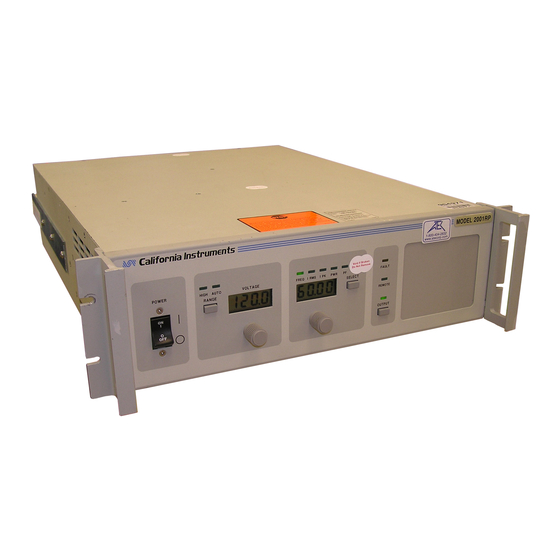
- Page 8 Figure 2-1: Available RMS Current as function of Output Voltage and Frequency......4 Figure 2-2: Rack Mount Slides (-RMS option) position............... 11 Figure 3-1: Model 2001RP AC Power Source ................... 12 Figure 3-2: Rear Panel View ....................... 13 Figure 3-3: Internal Adjustments and Jumper Locations, Input Line Voltage 103 to 127....16 Figure 3-4: Internal Adjustments and Jumper Locations, Line Voltage 187 to 253 Volts....
- Page 9 Table 10-3: Bit Configuration of Standard Event Status Register ........... 104 Table 10-4: *RST Default Parameter Values................... 106 Table 10-5: Status Registers - Power on Conditions............... 106 Table 10-6: Bit Configuration of Status Byte Register ..............108 Table 12-1: Bus Error Messages ..................... 118 viii April 2007 2001RP...
-
Page 10: Introduction
General Devices Company Model C300-120-B308 rack slides may be attached to the sides of the power source using 10-32 X 3/8 flat head screws. 2001RP-AV models may be factory configured with a single voltage range and fixed frequency output. 2001RP... -
Page 11: Specifications
Input to output = 2300 VAC, input to chassis = 1350 VAC. Output Parameter Specification Voltage Range 0 to 150 V or 300 V (standard ranges) 2001RP (see Section 3.7) 2001RP-AV 115 V and 230 V 115 V only (factory set) 2001RP-LZ 135 V and 270 V Resolution 0.1 volt Accuracy ±... - Page 12 Stability (24 hours) ± 0.015 % of full scale under constant load, line and temperature Total Power 2000 VA maximum at full scale voltage, either range Current Range Volt Range PEAK 2001RP 13.4 44.5 22.2 2001RP-AV 17.4 2001RP-LZ 14.8 49.4 24.7...
-
Page 13: Figure 2-1: Available Rms Current As Function Of Output Voltage And Frequency
± 15 ppm per year Impedance Steady State (voltage range * 0.0005) / load current. Transient R = 400 mOhm (approximate) L = 240 µHenry (approximate) 2001RP-LZ only Figure 2-1: Available RMS Current as function of Output Voltage and Frequency. April 2007 2001RP... -
Page 14: Measurements [Option]
0.2 % FS + 0.5 % reading Resolution Temp 0.06 % FS /°C Coefficients Available over bus only. Requires interface option Apparent Power Ranges 0 - 800.0 0 - 2000 Accuracy 0.3 % FS + 0.8 % reading Resolution 2001RP April 2007... -
Page 15: System Specification
(Option package -OP1 required) Rear panel connector: Output Active low TTL signal. Signal driven low for approximately 400 µsec any time output voltage or frequency programmed value changes. Signal level may be changed by removing jumpers to open collector. April 2007 2001RP... -
Page 16: Unit Protection
Width Depth Unit 13.26 48.26 56.62 5.22 22.29 inches Unit Weight: 2001RP 2001RP-AV 2001RP-LZ 39 Kg / 85 lbs 34 Kg / 76 lbs 39 Kg / 85 lbs Material: Steel chassis and panels. Aluminum cover. Finish: Yellow iridite, painted semi-gloss polyurethane Cooling: Fan cooled with air intake on the sides and exhaust to the rear. -
Page 17: Environmental
65 dBA maximum at 0% to 50% load, 75 dBA maximum greater than 50% load to 100% load. Measured at one meter. Safety: Tested to EN61010-1 European safety standards as required for the “CE” marking. Remote Control April 2007 2001RP... -
Page 18: Front Panel Controls
Status Indicators: 10 LEDs to indicate: REMOTE, FAULT, OUTPUT (ON/OFF), VOLTAGE RANGE HIGH, VOLTAGE RANGE AUTO FREQUENCY, CURRENT, PEAK CURRENT, POWER, POWER FACTOR DISPLAY MODES (Refer to paragraph 4.1.2). 2001RP April 2007... -
Page 19: Available Options
This option cannot be combined with option –LZ and must be specified on the original order. -L22 Locking knobs. Prevents front panel change of voltage and frequency. Low Impedance version: 2001RP-LZ • 135 V / 270 V volt ranges •... -
Page 20: Figure 2-2: Rack Mount Slides (-Rms Option) Position
/ 58.4 mm above the bottom edge of the front panel. Note: The 2001RP series models cannot be mounted in a cabinet by just using the front panel rack ears. They require additional support. Figure 2-2: Rack Mount Slides (-RMS option) position... -
Page 21: Installation And Functional Test
The AC Power System has been designed to operate from a single phase AC line voltage. The nominal operating voltage is either 120V or 230V line input. The 2001RP line input setting is shown on the type sticker located on the rear panel. -
Page 22: Figure 3-2: Rear Panel View
The AC Power Source has been designed to operate with a line frequency from 47Hz to 440 Hz. 3.2.3 Input Power The input power to the AC Power Source depends upon line and load conditions and may be as high as 2650 watts. Figure 3-2: Rear Panel View 2001RP April 2007... -
Page 23: Input Voltage Range Selection
The input voltage range is configured by moving one wire and relocating jumpers at W1-W4. See Figure 3-3 or Figure 3-4 for the location of the A6 board (DC Supply) where the jumpers and input wires are located. April 2007 2001RP... - Page 24 The low input voltage range is set by making the following connections inside the power source: Remove wire #5 (white, 10AWG) going to CR1-AC and re-connect to A6-E2 on the DC supply board. Jumper A6-W3 Remove Jumper A6-W2 Install Jumper A6-W1 Install, use jumper in spare holder W4. 2001RP April 2007...
-
Page 25: Figure 3-3: Internal Adjustments And Jumper Locations, Input Line Voltage 103 To 127
User and Programming Manual - Rev N Figure 3-3: Internal Adjustments and Jumper Locations, Input Line Voltage 103 to 127 April 2007 2001RP... - Page 26 The high input voltage range is set by making the following connections inside the power source: Remove wire #5 (white, 10AWG) going to A6-E2 on the DC supply board. and re-connect to CR1-AC Jumper A6-W1 Remove, place unused jumper in W4. Jumper A6-W2 Remove Jumper A6-W3 Install 2001RP April 2007...
-
Page 27: Figure 3-4: Internal Adjustments And Jumper Locations, Line Voltage 187 To 253 Volts
User and Programming Manual - Rev N Figure 3-4: Internal Adjustments and Jumper Locations, Line Voltage 187 to 253 Volts April 2007 2001RP... -
Page 28: Mechanical Installation
/ 58.4 mm above the bottom edge of the front panel. Note: The 2001RP series models cannot be mounted in a cabinet by just using the front panel rack ears. They require additional support. Figure 3-5: Rack Mount Slides (-RMS option) position 3.5 Input Wiring... -
Page 29: Output Connections
The table assumes the Remote Sense input is connected at the load. For 2001RP models with lower voltage ranges than 150 V , the wire gauge may have to be reduced. Numbers shown in Table 3-1 are for standard 2001RP model with 150 V range. -
Page 30: Figure 3-5: Input And Output Wiring
User and Programming Manual - Rev N AC Input AC Output Safety Cover Safety Cover L N Gnd Output Ferrite Clamp Input Ferrite Figure 3-6: Input and Output Wiring 2001RP April 2007... -
Page 31: Output Voltage Ranges
If this is not acceptable, the AC source should be operated in the high voltage range only and not in AUTO mode. 2001RP-AV units can be factory configured for single voltage range. In this case, the high voltage range is not present. April 2007... -
Page 32: Functional Test
Refer to Figure 3-7 for the test set up. For –LZ and –AV option units, the resistor values need to be adjusted as follows: Model Voltage Range Resistor Current (A 11.2 Ω 2001RP 13.4 45.0 Ω 6.6 Ω 2001RP-AV 17.4 26.4 Ω... -
Page 33: Figure 3-6: Test Setup 2001Rp
User and Programming Manual - Rev N Figure 3-7: Test Setup 2001RP April 2007 2001RP... -
Page 34: Current Limit - Modes Of Operation
User and Programming Manual - Rev N 3.9 Current Limit - Modes of Operation When the 2001RP is shipped from the factory, it is configured for the Constant Current Mode of operation. This mode means if the load current exceeds the programmed Current Limit value, the output current will continue at the programmed value. -
Page 35: Front Panel Operation
Note: Even if the front panel sockets are used to connect the load, the external voltage sense inputs must be connected. If it is impractical to connect the voltage sense lines at the load, they may be connected at the rear panel output terminal block. April 2007 2001RP... - Page 36 The output relay state is not changed however. RANGE - AUTO The Range AUTO LED indicates the 2001RP is in auto ranging mode and will switch voltage range automatically if the selected output voltage increments or decrements through the low range voltage limit.
-
Page 37: Figure 4-2: Voltage Auto Range Switch Over Points
SELECT button will only toggle between FREQ and CURR modes. HIGH Low to High switch-over Hysteresis High to Low switch-over Figure 4-2: Voltage Auto Range Switch Over Points April 2007 2001RP... -
Page 38: Figure 4-3: Shuttle Knob
If the 2001RP-AV is configured for a single voltage range, this button is disabled. The same button may be used to put the 2001RP in the AUTO voltage range change mode. This button toggles from Lo, Auto, Hi and back to Lo. The AUTO LED will illuminate when the AUTO range mode is enabled. - Page 39 Frequency or Current limit settings. After about 3 seconds on inactivity, this display switches to the selected measurement parameter. The SELECT button will define the operating mode or the selected measurement parameter for the right hand display. April 2007 2001RP...
-
Page 40: How To Examples
3. Use the right shuttle to set the frequency and current limit. The SELECT button will define the function of the shuttle as indicated by the display above it. The LED’s located above the display will indicate the selected function. 2001RP April 2007... - Page 41 Note: For peak current, power and power factor measurements, Option -OP1 is required. 4.2.4 Change the Voltage The voltage range can be changed as follows (If the 2001RP-AV is configured for a single voltage range, this does not apply): 1. Press the RANGE button located in the upper left corner. The output voltage will reset to 0 volts.
- Page 42 4.2.6 Measure Peak Inrush Current (Requires -OP1 Option) The peak current measurement function of the 2001RP uses a sample and hold circuit to track the highest peak current found until reset. The peak current sample and hold circuit is reset any time the user toggles away from the peak current display mode to a different measurement.
-
Page 43: Setting The Power On Initialization Values
User and Programming Manual - Rev N 4.3 Setting the Power on Initialization Values The 2001RP is supplied with default factory settings when the unit is powered up. The factory settings are: Parameter Factory default setting Voltage range Auto Voltage Range Voltage 5.0 Volt... -
Page 44: Current Limit Modes
User and Programming Manual - Rev N 4.4 Current Limit Modes The 2001RP supports two modes of current limiting. In either mode, the end user can set the RMS current level at which the current limit function will kick in. The available current... -
Page 45: Function Strobe [Option]
4.6 Remote Inhibit [Option] A Remote Inhibit BNC input is located on the rear panel of the 2001RP if the -OP1 option was specified at the time of purchase. This input may be used to kill the AC source output using an external control signal. -
Page 46: Principle Of Operation
The input power supply also generates 50 VDC and 15VSW1 from the 300 volt DC supply. The 50 VDC is used for fan and relay operation, +15VSW1 is used for the gate drive signal in the Amplifier Module. The switching circuit that generates these voltages is protected with a 1/2A fuse (F1). 2001RP April 2007... -
Page 48: Figure 5-1: Ac Power System Block Diagram
User and Programming Manual - Rev N Figure 5-1: AC Power System Block Diagram 2001RP April 2007... -
Page 49: Range Relay Board
The Amplifier Module has a thermo-switch mounted on its heat sink. If the heat sink temperature exceeds 100 degrees C, the amplifier shuts down and sends an OVT signal to the oscillator module. Logic low on the OVT control line will cause the front panel FAULT indicator to be illuminated. April 2007 2001RP... -
Page 50: Oscillator Module
5. Performs voltage dropouts at a designated phase angle. 5.7 IEEE 488/ RS232 Interface [Option] The 2001RP can optionally be outfitted with a combined RS232C and IEEE 488 interface board. This board assembly has opto-couplers for interface isolation. The GPIB address for the AC source is selected by a DIP switch on the rear panel. Only one interface can be active at any given time and must be selected using DIP switch position 6. - Page 51 AND 350 V ARE PRESENT IN CERTAIN SECTIONS OF THIS POWER SOURCE. THIS EQUIPMENT GENERATES POTENTIALLY LETHAL VOLTAGES. DEATH ON CONTACT MAY RESULT IF PERSONNEL FAIL TO OBSERVE SAFETY PRECAUTIONS. DO NOT TOUCH ELECTRONIC CIRCUITS WHEN POWER IS APPLIED. April 2007 2001RP...
-
Page 52: Calibration
135 V 14.8 A 36.5 Ω 270 V 7.4 A Table 6-1: Load Resistors and Current Some 2001RP-AV may be factory configured for single voltage range only. In this case, the 230 V range is not available. 2001RP April 2007... -
Page 53: Selecting Calibration Mode
CAL button located on the front panel using a pen or similar pointed object. Depressing this button for a brief moment will place the 2001RP in CAL mode, indicated by the illumination of the PF LED. While in CAL mode, the front panel controls are used to adjust the various calibration parameters. -
Page 54: Routine Calibration
Figure 6-1: Test Equipment Hookup for Routine Output and Voltage Measurement Calibration 6.3.1 Output Voltage Calibration 1. Select the high voltage range. Set the output frequency to 60 Hz (400 Hz on 2001RP- AV). Set the output voltage to 240 volts. ( 230 Volts on model 2001RP-AV) (115 Volts for 2001RP-AV with one range). -
Page 55: Figure 6-2: Test Equipment Hook-Up For Current And Power Measurement Calibration
2. Select the Low Voltage Range and program the output voltage to 10 volt AC. 3. Put the 2001RP in CAL mode by pressing the recessed CAL button. 4. Use the SELECT key to select the Voltage Measurement calibration mode. This mode is indicated by the FREQ LED. - Page 56 LCD until it reads as close as possible to 0.0. Do not go past a reading of zero. Note: The method of adjusting the low scale values for voltage, current and power insure that the measured value is correct for small values. Under a no-load condition, however, the measured value may not be 0 2001RP April 2007...
- Page 57 2. Select the High Voltage Range and program the output voltage to 240.0 volts AC or the maximum voltage available if less than 240 Volts. 3. Put the 2001RP in CAL mode by pressing the recessed CAL button. 4. Use the SELECT key to select the Voltage Measurement calibration mode. This mode is indicated by the FREQ LED.
-
Page 58: Non-Routine Calibration
If the Current Limit and High Current Measurement Range Adjustments are both adjusted, the High Current Measurement Range must be adjusted first. 1. Connect the test equipment as shown in Figure 6-2. Use the 11.3 ohm load. 2001RP April 2007... - Page 59 115 V for the –AV option) on the low voltage range and 60 Hz. (400 Hz for the –AV option). CAUTION: The amplifier wind tunnel must be covered for proper cooling if the adjustment takes more than 1 minute. 1. Adjust R50 on the Oscillator Board for an output current of 10.5 A. April 2007 2001RP...
-
Page 60: Figure 6-3: Internal Adjustments
User and Programming Manual - Rev N Figure 6-3: Internal Adjustments 2001RP April 2007... - Page 61 6.4.3 Open Sense Adjustment Connect the test equipment as shown in Figure 6-1. NOTE: The 2001RP must be configured for the Constant Current Mode of operation for this procedure. For this mode jumpers W1 and W2 on the controller must be removed.
-
Page 62: Service
SOLUTION The Remote Sense lines are not Connect AC voltmeter to Remote Sense connected at the same point monitored by lines on the Rear Panel Power Output the external voltmeter used for load terminal strip. regulation check. 2001RP April 2007... -
Page 63: Table 7-4: Distorted Output
Turn OUTPUT ON switch to “ON”. Current limit programmed down or to zero. Program current limit higher. Voltage programmed down or to zero. Turn amplitude control up. Fault LED is lit. Cycle Rear Panel power switch off and on. April 2007 2001RP... -
Page 64: Module Removal
Fan not working. Replace fan. Consult factory. If the 2001RP is configured to operate in the Constant Voltage mode, the Fault lamp comes on when the output load current has exceeded the programmed current limit value. If the AC Power Source Fault lamp is on, the following items may be at fault:... -
Page 65: Figure 7-1: Assembly Location
User and Programming Manual - Rev N Figure 7-1: Assembly Location April 2007 2001RP... - Page 66 The amplifier may be replaced by following this procedure in reverse order. Check the amplifier 20 A fuse (F2) located on the DC Supply Board, A6, and replace it if necessary. After an amplifier has been replaced, readjust its gain. 2001RP April 2007...
-
Page 67: Replaceable Parts
In order to ensure prompt, accurate service, please provide the following information, when applicable for each replacement part ordered. a. Model number and serial number of the instrument. b. California Instruments’ part number for the sub-assembly where the component is located. (California Instruments PART #) c. Component reference designator. (SEQ #) d. -
Page 68: Figure 7-2: Replaceable Fuse Locations
User and Programming Manual - Rev N Figure 7-2: Replaceable Fuse Locations 2001RP April 2007... -
Page 69: Remote Control
Remote Control 8.1 Introduction The 2001RP can be furnished with a combination IEEE-488 and RS232C control interface at the time of purchase. This interface is part of the -OP1 option package. This interface option also includes the California Instruments Graphical User Interface program - PGUI32. This Windows™... -
Page 70: Figure 8-1: Rear Panel View
User and Programming Manual - Rev N Figure 8-1: Rear Panel View 2001RP April 2007... -
Page 71: Ieee Interface
Refer to Figure 8-1 for the location of this switch. The IEEE address of the 2001RP is set using the DIP switch at the rear of the unit. Switch position 4 through 0 corresponds to bits 4 through 0 of the IEEE address. See figure below. -
Page 72: Rs232C Interface
8.4 RS232C Interface A suitable cable to connect the 2001RP AC Source to a 9 pin PC-AT style serial port is supplied with the source. If you are unable to locate this cable, you need to use a cable that conforms to the wiring diagram shown in Figure 8-3. - Page 73 DIM char AS STRING * 1 DIM resp AS STRING char = "" resp = "" char = INPUT$(1, #1) resp = resp + char LOOP UNTIL char = CHR$(10) 'Return result retstring = LEFT$(resp, LEN(resp) - 1) END FUNCTION April 2007 2001RP...
-
Page 74: Pgui32 Setup And Installation
PC. Standard null-modem cables obtained from a computer hardware store most likely will not work. For this reason, all California Instruments power sources that operate over RS232C are supplied with a RS232C 9 pin female to 9 pin female cable. - Page 75 When the installation has completed, remove the last disk from the floppy drive and store the disks in a safe place. Reboot the PC to activate the new settings. You are now ready to start using the PGUI32 software. April 2007 2001RP...
-
Page 76: Trouble Shooting - Rs232C
FIFO buffer. If you are using Windows 3.1 and experience the same problem, the latter method is the only resolution available to you so you should skip the next paragraph as well. 2001RP April 2007... -
Page 77: Figure 8-4: System Properties Dialog Box
UART FIFO’s and enable the hardware handshake to work correctly. 15. Click on the all OK buttons to close all dialog boxes that remain open. 16. This should enable the PGUI32 to work correctly. Figure 8-6: COM Port Properties Dialog Box April 2007 2001RP... - Page 78 11. Try to connect again. You may have to cycle the power on the AC source if it still shows the Err -100 display. Higher values than 40 may be set for the CmdDelay parameter if this fix does not resolve your problem. 2001RP April 2007...
-
Page 79: Trouble Shooting - Ieee-488 / Gpib
DIP switches on the 2001RP? The GPIB address selected must match the settings on the DIP switch. If changes are made to the DIP switch setting, the 2001RP power must be cycled off and on to have the new settings take effect. - Page 80 User and Programming Manual - Rev N Resolution for Symptom 2 The 2001RP has a limit on how fast it can process commands sent over the bus. When developing an application program that controls the 2001RP AC source, this must be considered.
-
Page 81: Pgui32 Distribution Files
Application directory files The following files are copied to the application directory. The application directory name is chosen by the user during the installation process. The default directory for the PGUI32 is: C:\Program Files\California Instruments\PGUI32 Pgui32.exe Executable Pgui32.hlp On Line Help file Pgui32.cnt... -
Page 82: Software Registration
PGUI32. Consult the included readme file for last minute program information. 8.9 Software Registration Updates of this and other California Instruments programs are posted on a regular basis on the California Instruments web site. You can find available programs by selecting the Software, GUI's and Drivers menu. -
Page 83: Introduction To Scpi
AC source to perform some action. • A response message consists of data in a specific SCPI format sent from the AC source to the controller. The AC source sends the message only when commanded by a program message called a "query." April 2007 2001RP... -
Page 84: Figure 9-1: Partial Command Tree
If you now enter :RANGe you have reached the end of the command string. The active header path remains at :RANGe If you wished, you could have entered :RANGe 150 ;LEVel 115 and it would be accepted as a compound message consisting of: 1. SOUR:VOLT:RANG 150. 2001RP April 2007... - Page 85 The message terminator after LEVel 115 returns the path to the root. Note: The 2001RP interface buffer is limited to 45 characters + [LF], however. As such, compound commands should be used with care to make sure they do not exceed this buffer message length limit.
-
Page 86: Using Queries
The following command message is briefly described here, with details in subsequent paragraphs. Data Query Indicator Message Unit Header SOUR:VOLT 80; FREQ 60; :CURR? <NL> Header Message Root Message Separator Unit Specifier Terminator Separator Figure 9-2: Command Message Structure The basic parts of the above message are: 2001RP April 2007... - Page 87 Header Separator If a command has more than one header, you must separate them with a colon (SYSTem:ERRor LIMit:FREQuency:LOW). Optional Headers The use of some headers is optional. Optional headers are shown in brackets, such as VOLTage[:LEVel] 100. April 2007 2001RP...
- Page 88 (<NL>), which is ASCII decimal 10 or hex 0A. In the examples of this manual, there is an assumed message terminator at the end of each message. If the terminator needs to be shown, it is indicated as <NL> regardless of the actual terminator character. 2001RP April 2007...
-
Page 89: Scpi Data Formats
String Response Data. Returns string parameters enclosed in double quotes. 9.6 Bus Throughput and Timing Considerations The 2001RP has a limit on how fast it can process commands sent over the bus. When developing an application program that controls the 2001RP AC source, this must be considered. -
Page 91: Scpi Command Reference
The subsystem command groups are listed in alphabetical order and the commands within each subsystem are grouped alphabetically under the subsystem. Commands followed by a question mark (?) take only the query form. When commands take both the command and query form, this is noted in the syntax descriptions. April 2007 2001RP... -
Page 92: Calibration Subsystem
SYSTem:SAVE command is issued before turning the Cal state off. CAL:STAT 0 Turns calibration mode off. CAL:STAT 1 Turns calibration mode on. Command Syntax CALibrate:STATe 0|1 Parameters <Bool> Examples CAL:STAT 1 CAL:STAT 0 Related Commands CAL[:SOUR] CAL:MEAS SYST:SAVE 2001RP April 2007... - Page 93 This command affects the calibration of the AC current measurement zero offset. Command Syntax CALibrate:MEASure:CURRent:ZERO <NRf> Parameters <NRf> (value range -127 to +127) Examples CAL:MEAS:CURR:ZERO +12 Query Syntax CALibrate:MEASure:CURRent:ZERO? Returned Parameters <NR1> (value range -127 to +127) Related Commands CALibrate:MEASure:CURRent April 2007 2001RP...
- Page 94 This command affects the calibration of the rms voltage measurement zero offset. Command Syntax CALibrate:MEASure:VOLTage:ZERO <NRf> Parameters <NRf> (value range -127 to +127) Examples CAL:MEAS:VOLT:ZERO +4 Query Syntax CALibrate:MEASure:VOLTage:ZERO? Returned Parameters <NR1> (value range -127 to +127) Related Commands CALibrate:MEASure:VOLTage 2001RP April 2007...
- Page 95 This command will set the calibration coefficient for the AC full scale output voltage. Command Syntax CALibrate[:SOURce]:VOLTage <NRf> Parameters <NRf> (a value between -127 and +127) Examples CAL:VOLT -2 Query Syntax CALibrate:VOLTage? Returned Parameters <NR1> (value range -127 to +127) Related Commands CAL:STAT April 2007 2001RP...
-
Page 96: Measurement Subsystem
This query returns the rms value of the output AC current being sourced at the output terminals. Note that the output relay must be closed to obtain current flow. Query Syntax MEASure:CURRent? Parameters None Examples MEAS:CURR? Returned Parameters <NR2> OUTP 0 ⎜ 1 Related Commands MEAS:CURR:AMPL:MAX? 2001RP April 2007... - Page 97 Available choices are high range (0), low range (1) or auto ranging (2). See measurement specifications (section 2.2) for actual range values. Query Syntax MEASure:CURRent:RANGe Parameters 0 | 1 | 2 Examples MEAS:CURR:RANG? Returned Parameters <NR2> Related Commands MEAS:CURR? MEAS:CURR:AMPL:MAX? April 2007 2001RP...
- Page 98 This value is always between 0.00 and 1.00. If the current measured is too low to determine the power factor, a 1.00 value is returned. Query Syntax MEASure:POWer:PFACtor? Parameters None Examples MEAS:POW:PFAC? Returned Parameters <NR2> Related Commands MEAS:POW? MEAS:POW:APP? 2001RP April 2007...
-
Page 99: Source Subsystem
Command Syntax [SOURce:]CURRent <NRf> Parameters 0 to a value specified by the LIM:CURR Unit A (rms amperes) *RST Defined by the PON Examples CURR 5 Query Syntax CURRent? Returned Parameters <NR2> Related Commands VOLT:RANG April 2007 2001RP... - Page 100 [SOURce:]VOLTage This command programs the AC rms output voltage level of the power source. The maximum voltage value allowed is determined by the selected voltage range. For 2001RP- AV models configured for single voltage range, only one range is available.
- Page 101 This command sets the voltage range of the power source . Two voltage ranges are available: a 150 volt range and a 300 volt range. However, 2001RP units with optional voltage ranges are available as well. In this case, the actual voltage range values will be different.
- Page 102 To determine the actual voltage range in which the unit is operating, the VOLT:RANG? command query can be used. For 2001RP-AV models configured for single voltage range, only one range is available. In this case, the VOLT:RANGe:AUTO command has no meaning and should not be used.
-
Page 103: Output Subsystem
This avoids hot switching the output relay contacts. Command Syntax OUTPut[:RELay] <bool> Parameters <Bool> 0 | 1 *RST Value defined by the PONS Examples OUTP 1 Query Syntax OUTPut? Returned Parameters 0 | 1 Related Commands OUTP:DROP OUTP:STAR April 2007 2001RP... - Page 104 This query will return a <Bool> indicating if the output time specified has expired (0) or the drop is still in progress (1). Command Syntax OUTPut:DROP <NRf> Parameters <NRf> | none *RST Value none Examples OUTP:DROP 0.001 Query Syntax OUTP:DROP? Returned Parameters 0 | 1 Related Commands OUTP:STAR:STAT OUTP:STAR:PHAS 2001RP April 2007...
- Page 105 Command Syntax OUTPut:STARt:PHASe <NR2> Parameters 0 | 90 | 180 | 270 *RST Value Examples OUTP:STAR:PHAS 90 Query Syntax OUTPut? Returned Parameters 0 | 90 | 180 | 270 Related Commands OUTP:DROP OUTP:STAR:STAT April 2007 2001RP...
-
Page 106: Limit Subsystem
<NR2> LIMit:FREQuency:LOW? This command queries the lower frequency limit of the power source. On the 2001RP-AV, the frequency range may have been factory configured to a fixed single value. In this case, the High and Low frequency limits will be set to the same value and both queries will return the same number. - Page 107 If the voltage limit value is less than 201 volt, the 2001RP is configured for single voltage range operation. If a value above 200 volt is returned, the 2001RP has a high and a low voltage range. On dual range configurations, the maximum voltage in the high range is returned and this value must be even.
-
Page 108: Display Subsystem
Peak Current Power Power Factor Table 10-1: Mode Command Encoding Command Syntax DISPlay:MODE <NR2> Parameters 1 | 2 | 3 | 4 | 5 *RST Value Examples DISP:MODE 2 Query Syntax DISPlay:MODE? Returned Parameters <NR1> Related Commands none 2001RP April 2007... -
Page 109: System Commands
This command sets the interface in Local state, which enables the front panel controls. This command only applies to the RS232C interface. If IEEE 488 is used, the remote/local state is determined by the REN line on the IEEE 488 interface. Command Syntax SYSTem:LOCal Parameters None Example SYST:LOC Related Commands SYST:REM April 2007 2001RP... - Page 110 AC source. This command is only valid while the AC source is in the Calibration mode. (See section 10.2.1 for details). Command Syntax SYSTem:SAVE Parameters none Examples SYST:PON Related Commands CAL:STAT 2001RP April 2007...
-
Page 111: Common Commands
Return event status register *IDN? Return instrument identification *RCL <n> Recall instrument state *RST Reset *SAV <n> Save instrument state *SRE <n> Set service request enable register *SRE? Return service request enable register *STB? Return status byte April 2007 2001RP... -
Page 112: Table 10-2: Bit Configuration Of Standard Event Status Enable Register
Bit Weight Command error Device-dependent error Execution error Query error Power-on Command Syntax *ESE <NRf> Parameters 0 - 255 Power-On Value Example *ESE 129 Query Syntax *ESE? Returned Parameters <NR1>(Register value) Related Commands *ESR? *STB? 2001RP April 2007... -
Page 113: Table 10-3: Bit Configuration Of Standard Event Status Register
If the *ESR? returns the value of the status bits in the ESR register. Refer to Table 10-3 for the status bits and their meaning. Table 10-3: Bit Configuration of Standard Event Status Register Bit Position Bit Name used used used Bit Weight Command error Device-dependent error Execution error Query error Power-on April 2007 2001RP... - Page 114 Example "CI,2001RP,12345,Rev 1.0" The following table shows the series of queries that may be used to detect the presence of a 2001RP, a 2001RP-AV or a 2001RP-LZ and to determine the frequency range setting of a 2001RP-AV: Step Query command...
-
Page 115: Table 10-4: *Rst Default Parameter Values
SYSTem:KLOCk command. This may put the unit in local if this state is set to 0. To avoid this, either set the SYSTem:KLOCk state to 1 or follow the *RST command with a SYST:REM command. See SYSTem:KLOCk for information on the power up remote / local state. April 2007 2001RP... - Page 116 (by programming it with 0), the source cannot generate an MSS bit. Command Syntax *SRE <NRf> Parameters 0 to 255 Default Value Example *SRE 255 Query Syntax *SRE? Returned Parameters <NR1>(Register binary value) Related Commands *ESE *ESR 2001RP April 2007...
-
Page 117: Table 10-6: Bit Configuration Of Status Byte Register
2 - 0 Bit Name OPER QUES not used Bit Weight OPER operation status summary master status summary event status byte summary QUES questionable status summary message available Query Syntax *STB? Returned Parameters <NR1> (Register binary value) April 2007 2001RP... -
Page 118: Programming Examples
11.2 Bus Throughput and Timing Considerations The 2001RP has a limit on how fast it can process commands sent over the bus. When developing an application program that controls the 2001RP AC source, this must be considered. -
Page 119: Programming The Output
The VOLT:RANGe command is coupled with the CURRent command. This means that the maximum current limit that can be programmed at a given time depends on the voltage range setting in which the unit is presently operating. April 2007 2001RP... - Page 120 RMS current limit is reached. Note: The CURRent command is coupled with the VOLTage:RANGe.This means that the maximum current limit that can be programmed at a given time depends on the voltage range setting in which the unit is presently operating. 2001RP April 2007...
-
Page 121: Making Measurements
MEAS:CURR:AMPL:MAX? /* retrieves peak current reading. To measure the current crest factor, use: MEAS:CURR:CRES? Power Measurements To measure the true power, use: MEAS:POW:REAL? To measure the apparent power, use: MEAS:POW:APP? To measure the power factor, use: MEAS:POW:PFAC? April 2007 2001RP... -
Page 122: Status Registers
Status Byte, and Service Request Enable registers and the Output Queue perform standard IEEE-488 functions as defined in the IEEE 488.2 Standard Digital Interface for Programmable Instrumentation. 12.1 Power-On Conditions Refer to the *RST command description in paragraph 10.9.6 for the power-on conditions of the status registers. 2001RP April 2007... -
Page 123: Standard Event Status Group
The Output Queue is a first-in, first-out (FIFO) data register that stores AC source-to- controller messages until the controller reads them. Whenever the queue holds one or more bytes, it sets the MAV bit (bit 4) of the Status byte register. April 2007 2001RP... -
Page 124: Examples
When an Event register is read, it is cleared. This also clears the corresponding summary bit. Step 3 : Remove the specific condition that caused the event. If this is not possible, the event may be disabled by programming the corresponding bit of the status group Enable. 2001RP April 2007... -
Page 125: Appendix A: Scpi Command Tree
:FREQuency :VOLTage [:LEVel] :RANGe :OUTPut OUTPut [:RELay] :DROP :STARt [:STATe] :PHASe MEASurement :CURRent? :AMPLitude :MAX? :RESet :CREStfactor :RANGe :POWer [:REAL]? :APParent? :PFACtor? :VOLTage? DISPlay :MODE SYSTem :PON :REMote :LOCal :KLOCk :SAVE LIMit :CURRent :VOLTage :FREQuency :LOW :HIGH April 2007 2001RP... -
Page 126: Appendix B: Scpi Conformance Information
User and Programming Manual - Rev N Appendix B: SCPI Conformance Information SCPI Version The RP Series AC power sources conform to SCPI version 1990.0. 2001RP April 2007... -
Page 127: Appendix C: Error Messages
Generally caused by too many errors being generated without reading error status, causing error buffer to overflow. -400 "Query error" Generally caused by sending a query followed by another command without accepting the query response first. Table 12-1: Bus Error Messages April 2007 2001RP... -
Page 128: Index
Frequency CALibrate:MEASure:PCURrent:ZERO ..84 specification ..........4 CALibrate:MEASure:PCURrent[ FREQuency ..........92 FSCale] ............. 84 frequency range CALibrate:MEASure:POWer:ZERO ... 86 2001RP-AV ..........98 CALibrate:MEASure:POWer[ fixed............98 FSCale] ............. 86 front panel ..........27, 60 CALibrate:MEASure:VOLTage:ZERO ..86 lock ............28 CALibrate:MEASure:VOLTage[ Function Strobe .......... - Page 129 ...........60 models SYSTem:ERRor? ........101 supported........... 60 SYSTem:KLOCk..........101 SYSTem:LOCal ...........101 SYSTem:PON..........102 OUTPut:DROP..........96 SYSTem:REMote ........102 OUTPut:STARt:PHASe......... 97 SYSTem:SAVE..........102 OUTPut:STARt[:STATe] ....... 97 OUTPut[:RELay] ........... 95 Overcurrent ............. 7 Temperature overload ............28 operating,storage .........9 Overtemperature ..........7 terminator............80 RS232C............63 April 2007 2001RP...
- Page 130 99 Input ............. 7 single ............99 troubleshooting..........53 voltage ranges ..........23 VOLTage:RANGe:AUTO ......94 VOLTage:RANGe[:LEVel] ......93 Vibration ............9 Voltage specification ..........2 Weight............. 7 VOLTage ............92 wiring voltage range input............20 2001RP April 2007...