Advertisement
Quick Links
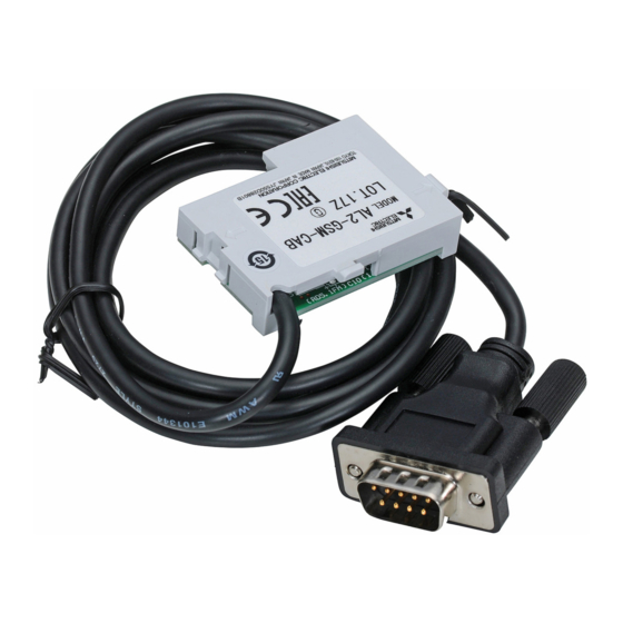
AL2-GSM-CAB
Hardware manual
Hardware-Handbuch
Manuel du matériel
Manuale dell´hardware
Manual del hardware
Maskinvaruhandbok
JY992D97201C
ENG
1. INTRODUCTION
α
The AL2-GSM-CAB can be used to connect
2 Series Controllers to a normal or GSM modem. The
AL2-GSM-CAB can transfer Short Message Service (SMS) data to a GSM modem for transmission to
mobile phones and mail addresses or can facilitate remote monitoring functions and program transfers
via normal modems. RS-232C communication to a personal computer can also be accomplished if an
adaptor cable is used.
This manual contains text, diagrams, and explanations which will guide the reader in the
correct installation and use of the AL2-GSM-CAB
understood before attempting to install or use the unit. Further information can be found in
α
the
2 HARDWARE and PROGRAMMING MANUALS.
Note:
• This cable cannot be used for any other applications.
α
• This cable does not attach to the
Series Controller.
• Simultaneous communication through both ports of the
result in a damaged program or a malfunction in the controller.
1.1 External Dimensions
1 5 0 0 ( 4 ' 1 1 " )
α
2 series side
4 6 . 3
1 0 . 2 ( 0 . 4 " )
( 1 . 8 2 " )
2. INSTALLATION
When installing AL2-GSM-CAB refer to Figure 1.
Caution
• Persons trained in the local and national electrical standards must install or remove the
AL2-GSM-CAB.
• Turn off the power supply when installing or removing the AL2-GSM-CAB.
• Put the cover back on after either installing or removing the AL2-GSM-CAB.
• Under no circumstances will Mitsubishi Electric be liable or responsible for any
consequential damage that may arise as a result of the installation or use of this
equipment.
• Do not pull on the cord, otherwise the cable may be damaged.
α
• When communicating to
2 series via GSM modem, the power supply for both units
must be turned ON at the same time. If they are not started up at same time, the
series will not communicate via GSM modem.
1) Releace screw 'A' and keep.
α
2) Carefully remove the factory fitted
2 expansion port cover or special module cover.
3) Install the AL2-GSM-CAB into the cavity, carefully placing the cable in the channel located on the
input terminal side.
α
4) Replace the
2 cover or special module taking care that there is no interference with the AL2-
GSM-CAB.
5) Tighten screw 'A' to a torque of 0.4 N·m.
. E C K H A
D o n ' t t o u c h
E N G
1
G E R
N i c h t b e r ü h r e n
F R E
N e p a s t o a c h e r
A L 2 - 2 4 M R - D
O U T 1
GER
1. EINLEITUNG
Das AL2-GSM-CAB wird verwendet, um die
Modem zu verbinden. Es kann SMS-Data an ein GSM-Modem zur Weiterleitung an Mobiltelefone oder
Email-Adressen übertragen.
Es ermöglicht weiterhin Remote-Überwachungs-Funktionen und mit normalen Modems Programm-
Übertragungen.
Dieses Handbuch enthält Texte, Diagramme und Erklärungen, die dem Benutzer die
α
2 Modem Cable. It should be read and
korrekte Installation und Nutzung des AL2-GSM-CAB
sollte vor einer Installation oder Nutzung des Geräts sorgfältig durchgelesen werden.
Weitere Informationen erhalten Sie im HARDWARE und PROGRAMMING-Handbuch.
Hinweise:
α
2 Series Controllers may
1.1 Abmessungen
Dimensions : mm (inches)
modem side
α
Seite der
2-
(9-pin D-Sub male)
Steuerung
2. INSTALLATION
Bitte beachten Sie beim Anschluss des AL2-GSM-CAB Figure 1.
Vorsicht
α
2
1) Entfernen Sie die Schraube 'A'.
2) Entfernen Sie vorsichtig die Abdeckung oder das Erweiterungsmodul.
3) Stecken Sie das AL2-GSM-CAB an den dafür vorgesehenen Steckplatz und verlegen Sie das
Kabel in den dafür vorgesehenen Kanal.
4) Bringen Sie die Abdeckung oder das Erweiterungsmodul vorsichtig wieder an. Achten Sie dabei
darauf, dass Sie das AL2-GSM-CAB nicht beschädigen.
5) Ziehen Sie die Schraube 'A' mit einem Drehmoment von 0,4 Nm fest.
2
D C I N P U T
+
-
( A )
( B )
1
2
3
4
5
6
7
8
9
1 0
1 1
1 2
1 3
1 4
1 5
+
-
D C I N P U T
( A )
( B )
1
2
3
4
5
6
7
8
9
1 0
1 1
1 2
1 3
1 4
1 5
P O W E R
P O W E R
2 4 V D C
2 4 V D C
E S C
A
E S C
+
+
-
-
O K
O K
A L 2 - 2 4 M R - D
R E L A Y
R E L A Y
O U T P U T
5
6
7
8
9
O U T P U T
O U T 2
O U T 3
O U T 4
O U T
O U T 1
O U T 2
O U T 3
O U T 4
O U T
5
7
8
9
α
2-Steuerung mit einem normalen oder einem GSM-
α
2-Modem-Kabels erläutern. Es
• Dieses Kabel kann nicht anderweitig verwendet werden.
α
• Dieses Kabel kann nicht in Verbindung mit der
-Steuerung verwendet werden.
• Eine gleichzeitige Kommunikation über diese Schnittstelle und die
α
Programmierschnittstelle der
2-Steuerung kann zur Beschädigung des Programms
oder einer Fehlfunktion der Steuerung führen.
1 5 0 0
Abmessungen in mm
Seite des Modems
(9-pin D-SUB männlich)
4 6 . 3
1 0 . 2
• Das AL2-GSM-CAB darf nur von Personen installiert oder entfernt werden, die mit den
nationalen elektrotechnischen Bestimmungen vertraut sind.
• Schalten Sie die Spannungsversorgung ab, bevor Sie das Kabel anschließen oder
entfernen.
• Bringen Sie nach der Installation oder der Deinstallation des AL2-GSM-CAB die
Abdeckung wieder an.
• MITSUBISHI ELECTRIC übernimmt unter keinen Umständen die Haftung oder
Verantwortung für einen Schaden, der aus einer unsachgemäßen Installation oder
Anwendung der Geräte oder des Zubehörs entstanden ist.
• Ziehen Sie nicht an dem Kabel, da dieses dadurch beschädigt werden kann.
α
• Bei der Kommunikation mit der
2-Steuerung über ein GSM-Modem muss die
Spannungsversorgung beider Geräte gleichzeitig eingeschaltet werden. Werden beide
α
Steuerung nicht gleichzeitig eingeschaltet, kann die
2-Steuerung nicht über das
Modem kommunizieren.
I n s t a l l
3
4
R
Q
D C I N P U T
D C I N P U T
+
-
( A )
( B )
1
2
3
4
5
6
7
8
9
1 0
1 1
1 2
+
-
( A )
( B )
1
2
3
4
5
6
7
8
9
1 0
1 1
1 2
1 3
1 4
1 5
P O W E R
P O W E R
2 4 V D C
2 4 V D C
E S C
E S C
+
+
R e m o v e
-
-
O K
O K
S
A L 2 - 2 4 M R - D
A L 2 - 2 4 M R - D
R E L A Y
R E L A Y
O U T P U T
O U T P U T
5
6
7
8
O U T 1
O U T 2
O U T 3
O U T 4
O U T
5
6
7
8
9
O U T 1
O U T 2
O U T 3
O U T 4
O U T
Q
R
FRE
1. INTRODUCTION
Le AL2-GSM-CAB peut être utilisé pour connecter les contrôleurs des séries
ou à un modem GSM. Le AL2-GSM-CAB peut transférer des données SMS (Short Message Service) à
un modem GSM pour la transmission à des téléphones portables ou à des adresses de courrier
électronique ou pour faciliter les fonctions de surveillance à distance et les transferts de programme via
les modems normaux. La communication RS 232C avec un ordinateur peut également être effectuée si
un câble adaptateur est utilisé.
Ce manuel contient des textes, diagrammes et explications destinés à guider le lecteur
dans l'installation correcte et l'utilisation du câble de modem AL2-GSM-CAB
nécessaire de l'avoir lu et compris avant d'essayer d'installer ou d'utiliser l'unité. Vous
trouverez de plus amples informations dans les manuels de programmation et de matériel
α
2.
Remarque :
• Ce câble ne peut pas être utilisé pour d'autres applications.
• Ce câble ne connecte pas le contrôleur des séries
• Une communication simultanée par les deux ports des contrôleurs des séries
entraîner un programme endommagé ou une défaillance dans le contrôleur.
1.1 Dimension extérieures
1 5 0 0
α
côté séries
2
4 6 . 3
1 0 . 2
2. INSTALLATION
Se référer à la figure 1 lors de l'installation du AL2-GSM-CAB.
Attention
• Seules les personnes formées conformément aux standards électriques locaux et
nationaux sont habilitées à installer et à remplacer le AL2-GSM-CAB.
• Couper l'alimentation électrique avant d'installer ou de remplacer le AL2-GSM-CAB.
• Replacer le couvercle après avoir installé ou enlevé le AL2-GSM-CAB.
• Mitsubishi Electric ne répondra ou ne sera rendu responsable en aucun cas des
dommages consécutifs à l'installation ou à l'utilisation de cet équipement.
• Ne pas tirer sur le cordon.
Tirer sur le cordon peut endommager le câble.
• Lors de la communication avec les séries
deux unités doit être mise en marche en même temps. Si elles ne sont pas mises en
route au même instant, les séries
1) Dévisser la vis « A » et la conserver.
2) Retirer avec précaution le couvercle du port d'extension
module spécial.
3) Installer le AL2-GSM-CAB dans son emplacement, placer soigneusement le câble dans le canal
situé sur le côté de connexion de l'entrée.
α
4) Replacer le couvercle
2 ou le module spécial en faisant attention qu'aucune interférence avec le
AL2-GSM-CAB n'intervienne.
5) Serrer la vis « A » avec un couple de serrage de 0,4 N·m.
5
D C I N P U T
1 3
1 4
1 5
+
-
( A )
( B )
1
2
3
4
5
6
7
8
9
1 0
1 1
1 2
1 3
1 4
1 5
P O W E R
2 4 V D C
E S C
A
+
-
O K
A L 2 - 2 4 M R - D
R E L A Y
O U T P U T
9
O U T 1
O U T 2
O U T 3
O U T 4
O U T
5
6
7
8
9
α
2 à un modem normal
α
2. Il est
α
.
α
2 peut
Dimensions : mm
côté du modem
(9 broches D-Sub mâle)
α
2 via un modem GSM, l'alimentation des
α
2 ne communiqueront pas via le modem GSM.
α
2 monté en usine ou le couvercle du
Advertisement

Related Manuals for Mitsubishi AL2-GSM-CAB


Summary of Contents for Mitsubishi AL2-GSM-CAB
- Page 1 2) Retirer avec précaution le couvercle du port d'extension 2 monté en usine ou le couvercle du 3) Install the AL2-GSM-CAB into the cavity, carefully placing the cable in the channel located on the 1) Entfernen Sie die Schraube ‘A’.
- Page 2 4) Sätt tillbaka 2-kåpan eller specialmodulen, försiktigt så att inte AL2-GSM-CAB kommer i kläm. 3) Installare lo AL2-GSM-CAB nella cavitá , mettendo con cautela il cavo nel canaletto sistemato sul por el lado del terminal de entrada. lato del terminal di input.