Garmin GTX 330 Installation Manual
Hide thumbs
Also See for GTX 330:
- Installation manual (106 pages) ,
- System maintenance manual (56 pages) ,
- Pilot's manual (13 pages)

Related Manuals for Garmin GTX 330


Summary of Contents for Garmin GTX 330
- Page 1 330, GTX 330D TRANSPONDER INSTALLATION MANUAL â â â â GARMIN International, Inc. 1200 E. 151 Street Olathe, KS 66062 USA 190-00207-02 Revision 1 March 2002...
- Page 2 Information in this document is subject to change without notice. GARMIN reserves the right to change or improve its products and to make changes in the content without obligation to notify any person or organization of such changes or improvements.
- Page 3 TABLE OF CONTENTS To be supplied GTX 330 Installation Manual Page i 190-00207-02 Rev 1...
- Page 4 This page intentionally left blank Page ii GTX 330 Installation Manual Rev 1 190-00207-02...
-
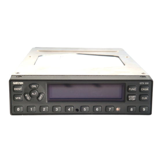
Page 5: Equipment Description
18 seconds. As with other Mode A/Mode C transponders, the GTX 330 replies with any one of 4,096 codes, which differ in the position and number of pulses transmitted. By replying to ground transmissions or TCAS interrogations, the GTX 330 enables ATC to display aircraft identification, altitude and ground speed as well as identification numbers on ATC radar screens or TCAS traffic indicators. - Page 6 Temperature, Altitude Hold, Density Altitude and the ability to enter flight ID or tail numbers. • Digitally recorded voice and discrete warning annunciator activated by Altitude Hold when limits are exceeded. • Diversity: GTX 330 is available with or without the Diversity feature. GTX 330 TECHNICAL SPECIFICATIONS 1.4.1 GTX 330 Electrical Specifications SPECIFICATION...
-
Page 7: Specification
1.4.2 Physical Characteristics of the GTX 330 SPECIFICATION CHARACTERISTIC Bezel Height 1.65 inches (42 mm) Bezel Width 6.25 inches (159 mm) Rack Height (Dimple to Dimple) 1.68 inches (43 mm) Rack Width 6.30 inches (160 mm) Depth Behind Panel with 11.25 inches (286 mm) -
Page 8: Additional Equipment Required
FAA AC 43.13-2A. INSTALLATION APPROVAL The conditions and tests required for TSO approval of the GTX 330 Transponder and antenna are minimum performance standards. It is the responsibility of those desiring to install this transponder and antenna either on or within a specific type or class of aircraft to determine that the aircraft installation standards are within the TSO standards. -
Page 9: Limited Warranty
LIMITED WARRANTY GARMIN warrants this product to be free from defects in materials and manufacture for one year from the date of purchase. GARMIN will, at its sole option, repair or replace any components that fail in normal use. Such repairs or replacement will be made at no charge to the customer for parts or labor. - Page 10 This page intentionally left blank Page 1-6 GTX 330 Installation Manual Rev. 1 190-00207-02...
-
Page 11: Unpacking And Inspecting Equipment
If the unit is damaged, notify the carrier and file a claim. To justify a claim, save the original shipping container and all packing materials. Do not return the unit to GARMIN until the carrier has authorized the claim. -
Page 12: Installation Approval Considerations For Pressurized Aircraft
4. Obtain FAA Advisory Circular AC-183C and select (and contact) a DER from the roster of individuals identified thereunder. 5. Contact an aviation industry organization such as the Aircraft Electronics Association and request their assistance. Page 2-2 GTX 330 Installation Manual Rev. 1 190-00207-02... -
Page 13: Antenna Cable Installation
Supplier Information Vendor: Electronic current issue of issue of Qualified Cable Specialists Qualified Products List Products List QPL-17. 5300 W. Franklin Drive QPL-17. Franklin, WI 53132 Tel: 800-327-9473 414-421-5300 Fax: 414-421-5301 GTX 330 Installation Manual Page 2-3 190-00207-02 Rev. 1... -
Page 14: Cooling Air
The GTX 330 was designed to handle a constant 450 PRF, with short periods of 1200 PRF. Rate limit is set at 1200 PRF. A typical radar site would interrogate the transponder once every 5 to 10 seconds for approximately 100 msec at a 400 PRF rate. -
Page 15: Antenna Cable Connectors
3.1.2 Antenna Cable Connectors The antenna cable requires a BNC connector at the antenna and a male BNC “Blindmate” connector (P/N 330-00053-01, supplied with GTX 330 backplate assembly, 011-00582-00/01 at the transponder. Follow BNC connector manufacturer instructions for assembly of the BNC connector. -
Page 16: Post Installation Checkout
Be sure to check all aircraft control movements before flight is attempted to insure that the wiring harness does not touch any moving part. Verify proper operation of the transponder during a flight test under VFR conditions. Page 3-2 GTX 330 Installation Manual Rev. 1 190-00207-02... - Page 17 Figure 3-1 GTX 330 OUTLINE DRAWING GTX 330 Installation Manual Page 3-5 (Page 3-6 blank) 190-00207-02 Rev 1...
- Page 18 Figure 3-2 GTX 330 CONNECTOR/RACK ASSEMBLY DRAWING GTX 330 Installation Manual Page 3-7 (Page 3-8 blank) 190-00207-02 Rev 1...
- Page 19 Figure 3-3 GTX 330 RECOMMENDED PANEL CUTOUT DIMENSIONS GTX 330 Installation Manual Page 3-9 (Page 3-10 blank) 190-00207-02 Rev 1...
- Page 20 ARINC 429 OUT 2 B ARINC 429 IN 3 B ARINC 429 OUT 2 A EXTERNAL SUPPRESSION I/O ARINC 429 IN 1 A ARINC 429 IN 2 A Table 4-1. P3301 Pin Assignments GTX 330 Installation Manual Page 4-1 190-00207-02 Rev. 1...
- Page 21 RESERVED RESERVED RESERVED RESERVED RESERVED SWITCHED POWER OUT Table 4-1. P3301 Pin Assignments (Cont’d) * Ground to activate. Refer to Figure 4-1 on page 4-5 for GTX 330 interconnect wiring diagram. Page 4-2 GTX 330 Installation Manual Rev. 1 190-00207-02...
- Page 22 4.2.2 Lighting Bus The GTX 330 unit can be configured to track a 28 VDC, 14 VDC, 5 VDC or 5 VAC lighting bus using these inputs. The GTX 330 can also automatically adjust for ambient lighting conditions based on the photocell. Refer to sections 5.2.5.
- Page 23 These inputs are considered inactive if the voltage to ground is 11-33 VDC. NOTE The GTX 330 contains internal altitude code line isolation diodes to prevent the unit from pulling the encoder lines to ground when the transponder is turned off.
- Page 24 Table 4-8. ARINC 429 Pin Assignments The ARINC 429 outputs conform to ARINC 429 electrical specifications when loaded with up to 5 standard ARINC 429 receivers. Refer to sections 5.2.8. and 5.2.17. GTX 330 Installation Manual Page 4-5 190-00207-02 Rev. 1...
- Page 25 This page intentionally left blank Page 4-6 GTX 330 Installation Manual Rev. 1 190-00207-02...
- Page 26 Figure 4-1 GTX 330 INTERCONNECT WIRING DIAGRAM GTX 330 Installation Manual Page 4-5 (Page 4-6 blank) 190-00207-02 Rev 1...
- Page 27 Figure 4-2 DUAL TXP INTERCONNECT WIRING DIAGRAM, ENCODING ALTITUDE CONNECTIONS GTX 330 Installation Manual Page 4-7 (Page 4-8 blank) 190-00207-02 Rev 1...
-
Page 28: Post Installation Configuration And Checkout Procedure
5.1.1 Function Selector Switches The function selection switches are: • OFF Powers off the GTX 330. Pressing the STBY, ON or ALT key powers on the transponder displaying the last active identification code. • STBY Selects the standby mode. When in standby mode, the transponder will not reply to any interrogations. -
Page 29: Code Selection
Configuration Mode. NOTE The selected identification code should be entered carefully, either one assigned by air traffic control for IFR flight or an applicable VFR transponder code. Page 5-2 GTX 330 Installation Manual Rev. 1 190-00207-02... -
Page 30: Function Display
5.1.3 Function Display PRESSURE ALT Displays the altitude data supplied to the GTX 330 in feet, hundreds of feet (i.e., flight level), or meters, depending on configuration. FLIGHT TIME Displays the Flight Time, controlled by the START/STOP key or by one of three airborne sources (squat switch, GPS ground speed recognition or altitude increase) as configured during installation. -
Page 31: Configuration Pages
• Squat Switch Setup • Gray Code Input • External Switch State • Analog Input • RS232 Input Display • ARINC 429 Input Display #1 • ARINC 429 Input Display #2. Page 5-4 GTX 330 Installation Manual Rev. 1 190-00207-02... -
Page 32: Traffic Information Page
Message “0” is an on-off beeping tone. Message “1” through “5” are selected tones messages. 5.2.3 TRAFFIC INFORMATION PAGE TRAFFIC MESSAGES TRAFFIC INFORMATION Page Sets the Traffic Messages to tone, Message or Off. Traffic Information Services (TIS) provides notification of close proximity traffic. GTX 330 Installation Manual Page 5-5 190-00207-02 Rev. 1... -
Page 33: Display Mode Page
Selection Description MAN (Manual) Display backlighting is controlled manually by the pilot on the GTX 330 DISPLAY page. No backlight parameters can be entered when the manual mode is selected. DEFAULT. Display backlighting is automatically controlled, based AUTO (Automatic) on the parameters entered on this configuration page. When AUTO is selected, the DISPLAY page does not appear to the pilot. -
Page 34: Key Lighting Page
NOTE If a lighting bus (any selection other than PHOTO) is selected, and the lighting bus control is turned to its minimum (daytime) setting, the display brightness will track the GTX 330 photocell. SLOPE Sets the sensitivity of the display brightness to changes in the input level. The higher the number, the brighter the display will be for a given increase in the input level. - Page 35 PHOTO (Photocell) DEFAULT. Key lighting level is determined by the ambient light level as measured by the photocell on the GTX 330. Backlight level tracks a 14 volt DC aircraft lighting bus. Backlight level tracks a 28 volt DC aircraft lighting bus.
- Page 36 DATA SOURCE: ADLP or OFF. DEFAULTS to OFF. 5.2.9 RS 232 INPUT PAGE RS 232 INPUT (Altitude Source) RS 232 INPUT Page This is the electrical source for the GTX 330 altitude input. Selection Description DEFAULT. OFF. The altitude code input is not from a 429 source.
- Page 37 VFR ID (VFR Transponder Code) This field is the four-digit code that will be selected when the user presses the GTX 330 VFR key. In the United States, 1200 is the VFR code for any altitude. It is set to 1200 at the factory.
-
Page 38: Temperature Page
Aircraft Registration or Flight ID Number Pages NOTE It is VERY important to enter the Mode S address correctly in the GTX 330. During production of a GTX 330 the unit is initially set with an address of 0. The software recognizes this as an invalid address. When the unit... - Page 39 This field shows the status (1 = ground, 0 = open) of each of the ten gray code altitude inputs. This information may aid in installation troubleshooting. DECODED ALTITUDE This field displays the gray code altitude input in feet. Verify that it is the correct altitude. Page 5-12 GTX 330 Installation Manual Rev. 1 190-00207-02...
- Page 40 (the aircraft is on the ground as configured on the SETUP 2 page). 5.2.15 ANALOG INPUT Page ANALOG INPUT Page 5.2.16 RS 232 INPUT Page RS 232 INPUT Page 5.2.17 429 CHANNNELS Pages 429 CHANNELS 1 and 2 429 CHANNELS 3 and 4 GTX 330 Installation Manual Page 5-13 190-00207-02 Rev. 1...
- Page 41 This page intentionally left blank Page 5-14 GTX 330 Installation Manual Rev. 1 190-00207-02...
-
Page 42: Certification Documents
It is the applicant’s responsibility to determine the suitability of the documents for the ICA. Following is a suggested ICA for a GARMIN GTX 330 unit installation. Some of the checklist items do not apply, in which case they should be marked “N/A” (Not Applicable). - Page 43 Maintenance Instructions Maintenance of the GTX 330 is ‘on condition’ only. Periodic maintenance is not required. Refer to the GTX 330 Maintenance Manual. Troubleshooting Information Refer to the GTX 330 Maintenance Manual. Removal and Replacement Information Refer to section 2 of this manual. If the unit is removed and reinstalled, a functional check of the equipment should be conducted in accordance with section 5 of this manual.
- Page 44 43.9. This entry records the major alteration and identifies the original ICA location (e.g., Block 8 of FAA Form 337, dated ______) along with a statement that the ICA is now part of the aircraft’s inspection/maintenance requirements. GTX 330 Installation Manual Page A3 190-00207-02...
-
Page 45: Environmental Qualification Form
ENVIRONMENTAL QUALIFICATION FORM NOMENCLATURE: GTX 330 Airborne ATC/Mode S Transponder Equipment TYPE/MODEL/PART NO.: 010-00230–( ), which includes 011-00455–( ) TSO/JTSO COMPLIANCE: TSO – C112 Class 2A, and TSO - C74c Class 1A MANUFACTURER'S SPECIFICATION AND/OR OTHER APPLICABLE SPECIFICATION: 004-00099-00 Minimum Performance Specification... - Page 46 23.0 Equipment identified as Category X, no test required Icing 24.0 Equipment identified as Category X, no test required Electrostatic Discharge (ESD) 25.0 Equipment identified as Category X, no test required GTX 330 Installation Manual Page A5 190-00207-02 Rev. 1...
-
Page 47: Stc Permission
APPENDIX B STC PERMISSION Consistent with N8110.69 or Order 8110.4, Aviation Authority approved installers are hereby granted permission to use STC #(xxxxxxxxx) data to modify aircraft. GTX 330 Installation Manual Page B1 190-00207-02 Rev. 1... - Page 48 To be supplied Page B2 GTX 330 Installation Manual Rev. 1 190-00207-02...