Table of Contents
Advertisement
Quick Links
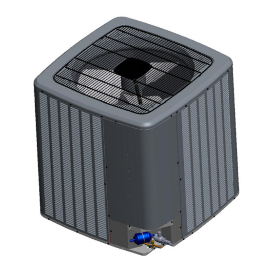
HEAT PUMP UNIT
*VZC20 Heat Pump Installation & service reference
Only personnel that have been trained to install, adjust,
service or repair(hereinafter, "service") the equipment
specified in this manual should service the equipment.
The manufacturer will not be responsible for any injury
or property damage arising from improper service or
service procedures. If you service this unit, you assume
responsibility for any injury or property damage which may
result. In addition, in jurisdictions that require one or more
licenses to service the equipment specified in this manual,
only licensed personnel should service the equipment.
Improper installation, adjustment, servicing or repair of
the equipment specified in this manual, or attempting to
install, adjust, service or repair the equipment specified in
this manual without proper training may result in product
damage, property damage, personal injury or death.
"Proper sizing and installation of equipment is critical to achieve optimal performance. Split system
air conditioners and heat pumps must be matched with appropriate coil components to meet ENERGY
STAR criteria. Ask your contractor for details or visit www.energystar.gov.
IMPORTANT – This product has been designed and manufactured to meet ENERGY STAR criteria for
energy efficiency when matched with appropriate coil components. However,
proper refrigerant charge and proper air flow are critical to achieve rated capacity and
efficiency. Installation of this product should follow the manufacturer's refrigerant charging and air
flow instructions. Failure to confirm proper charge and airflow may reduce
energy efficiency and shorten equipment life."
IOG-4013E
06/2021
WARNING
19001 Kermier Rd. Waller, TX 77484
www.goodmanmfg.com•www.amana-hac.com
© 2020-2021 Goodman Manufacturing Company, L.P.
is a registered trademark of Maytag Corporation or its related companies and is used under license. All rights
IMPORTANT SAFETY INSTRUCTIONS
The following symbols and labels are used throughout
this manual to indicate immediate or potential safety
hazards. It is the owner's and installer's responsibility to
read and comply with all safety information and instructions
accompanying these symbols. Failure to heed safety
information increases the risk of personal injury, property
damage, and/or product damage.
High Voltage!
Disconnect all power before servicing or
installing this unit. Multiple power sources may
be present. Failure to do so may cause property
damage, personal injury or death.
Do not wash the heat pump with excessive water. An electric
shock or fire could result.
reserved.
WARNING
CAUTION
Advertisement
Table of Contents

Related Manuals for Maytag Amana VZC20


Summary of Contents for Maytag Amana VZC20
-
Page 1: Important Safety Instructions
19001 Kermier Rd. Waller, TX 77484 www.goodmanmfg.com•www.amana-hac.com © 2020-2021 Goodman Manufacturing Company, L.P. IOG-4013E is a registered trademark of Maytag Corporation or its related companies and is used under license. All rights 06/2021 reserved. -
Page 2: Table Of Contents
INDEX Important Safety Instructions ........1 Shipping Inspection ............3 Codes & Regulations ............3 Features ................3 Installation Clearances ..........3 Rooftop Installations ...........4 Safe Refrigerant Handling ..........4 Refrigerant Lines ............5 Leak Testing (Nitrogen Or Nitrogen-Traced) ..7 Electrical Connections ..........8 System Start-Up Procedure ........10 Coolcloud™... -
Page 3: Shipping Inspection
CAUTION NOTICE HE UNIT HAS ITS OWN DOWN MODE SE THE DOWN Inverter Heat Pump models can only be matched with an MODE WHILE VACUUMING THE UNIT ACUUMING TOO LOW CAN AVPEC air handler or TXV-V** expansion valve kit. Damage CAUSE INTERNAL ELECTRICAL ARCING RESULTING IN A DAMAGED OR resulting from operation with any other combination is not... -
Page 4: Rooftop Installations
require placement beneath an obstruction there should The following elevation minimums are recommended: be a minimum of 60 inches between the top of the unit Design Temperature Suggested Miminum Elevation and the obstruction(s). The specified dimensions meet +15° and above 2 1/2"... -
Page 5: Refrigerant Lines
The liquid line must be insulated if more than 50 ft. of liquid WARNING line will pass through an area that may reach temperatures of 30 °F or higher than ambient in cooling mode and/or if O AVOID POSSIBLE EXPLOSION USE ONLY RETURNABLE the temperature inside the conditioned space may reach a DISPOSABLE... -
Page 7: Leak Testing (Nitrogen Or Nitrogen-Traced)
REFRIGERANT LINE CONNECTIONS Standing Pressure Test (Recommended before System Evacuation) IMPORTANT WARNING To avoid overheating the service valve, TXV, sensor or filter drier while brazing, wrap the component with a wet rag, To avoid the risk of fire or explosion, never use oxygen, or use a thermal heat trap compound. -
Page 8: Electrical Connections
WARNING 5000 4500 REFRIGERANT UNDER PRESSURE! 4000 Failure to follow proper procedures may cause property LEAK(S) 3500 damage, personal injury or death. PRESENT 3000 NOTE: Scroll compressors should never be used to evacuate or pump down a heat pump or air 2500 conditioning system. - Page 9 • Make sure the wirings will not be pinched by the front panel, and close the panel firmly. NOTICE • Route the conduit along the unit and so on to prevent wirings from being stepped on. • Never install a phase-advancing capacitor. As this unit is equipped with an inverter, installing a phase- advancing capacitor will not only deteriorate power Low Voltage Connections...
-
Page 10: System Start-Up Procedure
CAUTION POSSIBLE REFRIGERANT LEAK! O AVOID A POSSIBLE REFRIGERANT LEAK OPEN THE SERVICE VALVES 1/8” UNTIL THE TOP OF THE STEM IS FROM THE RETAINER CAUTION NSURE VALVES ARE OPEN AND ADDITIONAL CHARGE IS ADDED BEFORE APPLYING POWER Note: The following table lists the equivalent length gained from adding bends to the suction line. -
Page 11: Coolcloud™ Hvac Phone Application
Step 3. System Start-up Test Before starting the CHARGE MODE, turn off the Cool or Heat mode and electric heater or gas furnace. NOTICE a. Inverter units are charged by any of the following methods: • setting the “CR9” menu (Charge Mode) to ON through On initial power start-up, the outdoor unit will display code E11, signaling that initial SYSTEM test must be run. - Page 12 Charging Table SATURATED SUCTION PRESSURE SATURATED LIQUID PRESSURE TEMPERATURE CHART TEMPERATURE CHART SUCTION PRESSURE LIQUID PRESSURE OD AMBIENT TEMP R-410A °F R-410A °F PSIG PSIG < 65° F 65° F to 105° F > 105° F (degF) Subcooling Weigh in Weigh in 8°...
-
Page 13: Comfortbridge™ System
humidity sensor and dehumidification terminal. OUTDOOR UNIT DIPSWITCH FACTORY DEFAULT SETTINGS Without this type of thermostat, dehumidification Switch # Setting Function operation does not work. CT Communication Terminal Resister CT Communication Terminal Resister Cooling Emergency Mode* Dehumidification requires a thermostat capable of reading Cooling Emergency Mode* the indoor humidity level and allowing the user to set a * DS2 sw itch 1 and 2 both must be turned on during normal operation mode... - Page 14 (If using a CTK04 thermostat, please see the addendum Cooling Airflow Profile for further instructions.) • Profile A provides only an OFF delay of one (1) minute at 100% of the cooling demand airflow. Fault Code History The heat pump’s diagnostics menu provides access to the most recent faults.
- Page 15 Setting “A” allows for the same compressor operation 1. At Cool and Heat Hi speed trim, *VZC200601* with range as standard Dehumidification with lower CFM than **VC960804C, **VM970804C and *MVC800804C standard dehumidification (Standard). combination trim more than 5% settings are invalid. Trimmed up CFM makes miss matching error.
-
Page 16: Heat Pump Advanced Feature Menu
Heat Pump Advanced Feature Menu HEAT PUMP / FAULT CODE HISTORY SUBMENU ITEM INDICATION/USER MODIFIABLE OPTIONS COMMENTS (The Active and History Fault codes are displayed.) Active fault code and up to 6 fault code histories. ACTIVE (The Active Fault codes are displayed.) Active fault code only. - Page 17 Heat Pump Advanced Feature Menu HEAT PUMP / DEVICE SETTING (1) SUBMENU ITEM INDICATION(Units) COMMENTS BOOST MODE is ON by default. See BOOST BOOST MODE ENABLE OFF or ON MODE section of this manual for more details. If enabled, when the ambient outdoor temperature is greater than this selected value, boost mode will be operational.
- Page 18 Heat Pump Advanced Feature Menu HEAT PUMP / DEVICE SETTING (2) SUBMENU ITEM INDICATION(Units) COMMENTS Selecting "OFF" disables dehumidification Standard, OFF, A, B or C selecting. DEHUMIDIFICATION ENABLE "Standard", "A", "B" or "C" enables dehumidification. Selecting yes will reset any cooling setting to their RESET COOLING SETTINGS NO or YES factory defaults.
-
Page 19: Wiring Diagram
Wiring Diagram - 2 Tons *VZC200241** Wiring is subject to change. Always refer to the wiring diagram on the unit for the most up-to-date wiring. - Page 20 Wiring Diagram - 3 - 5 Tons *VZC200[36-60]1** Wiring is subject to change. Always refer to the wiring diagram on the unit for the most up-to-date wiring.
-
Page 21: Testing Capacitor Resistance
Testing Capacitor Resistance WARNING VOID CONTACT WITH THE CHARGED AREA •N EVER TOUCH THE CHARGED AREA BEFORE CONFIRMING THAT THE RESIDUAL VOLTAGE IS VOLTS OR LESS 1. S HUT DOWN THE POWER AND LEAVE THE CONTROL BOX FOR MINUTES 2. M AKE SURE TO TOUCH THE ARTH GROUND TERMINAL TO RELEASE THE STATIC ELECTRICITY FROM YOUR BODY TO PREVENT... - Page 22 Testing Capacitor Resistance WARNING VOID CONTACT WITH THE CHARGED AREA •N EVER TOUCH THE CHARGED AREA BEFORE CONFIRMING THAT THE RESIDUAL VOLTAGE IS VOLTS OR LESS 1. S HUT DOWN THE POWER AND LEAVE THE CONTROL BOX FOR MINUTES 2. M AKE SURE TO TOUCH THE ARTH GROUND TERMINAL TO RELEASE THE STATIC ELECTRICITY FROM YOUR BODY TO PREVENT...
- Page 23 HEATING ANALYSIS CHART POSSIBLE CAUSE X IN ANALYSIS GUIDE INDICATE "POSSIBLE CAUSE" Liquid stop valve does not fully open Gas stop valve does not fully open Line set restriction Line set length is too long Blocked filter-dryer OD EEV coil failure OD EEV failure Check valve failure –...
- Page 24 COOLING ANALYSIS CHART POSSIBLE CAUSE X IN ANALYSIS GUIDE INDICATE "POSSIBLE CAUSE" Liquid stop valve does not fully open Gas stop valve does not fully open Line set restriction Line set length is too long Blocked filter-dryer OD EEV coil failure OD EEV failure Check valve failure –...
-
Page 25: Troubleshooting
Troubleshooting ClimateTalk PCB LED Transmitted ClimateTalk t l u i t c Fault Code Display Message High electrical noise OD CTRL FAIL1 Indicates a general memory error. Replace control board if necessary Faulty control board Blocked/restricted condenser coil and/or Check and clean condenser coil and/or lines lines Check the opening of stop valve, should be full open;... - Page 26 Troubleshooting ClimateTalk PCB LED Transmitted ClimateTalk t a t t l u i t c o i t Fault Code Display Message Discharge thermistor inoperable or This error indicates the equipment is improperly connected Check discharge thermistor resistance and experiencing frequent high discharge Discharge thermistor is put on incorrect connections;...
- Page 27 Troubleshooting ClimateTalk PCB LED Transmitted ClimateTalk Fault Code Display Message Check installation clearances. Short circuit condition Check the opening of stop valve, should be full open; Stop valve not completely open Repair/replace if needed HIGH CURRENT Board detected a high current condition. Overcharge Check refrigerant charge level;...
- Page 28 Troubleshooting ClimateTalk PCB LED Transmitted ClimateTalk Fault Code Display Message This error indicates the equipment is Check and clean grille of any debris experiencing frequent outdoor control Obstruction in fan rotation Check wiring from outdoor fan motor to control board; board and/or motor faults.
- Page 29 Network Troubleshooting 3. Perform continuity check on wires to make sure cable If a network communication error code has occurred, use is OK. Replace the cable if necessary. the following steps to help troubleshoot the system. (For 4. Change both dip switches of DS1 on the outdoor unit network communication error codes, refer to the table control board to the opposite position.
-
Page 30: Setting Mode Display
Setting The Mode Display MODE DISPLAY INTRODUCTION A 3-digit display is provided on the printed circuit board (PCB) as a backup tool to the thermostat for reading faults, fault history, monitoring and setting up the unit. Follow the information provided in this section to learn how to use the mode display. DISPLAY The display consists of 3 digits. - Page 31 Setting The Mode Display NAVIGATING THROUGH THE DISPLAY SCREENS SCREEN The home or default screen on the display. This shows the most recent fault. SCREEN 1 To access, hold the RECALL button for 5 seconds at screen 0. SCREEN 2 To access, hold the RECALL button for 5 seconds at screen 1.
- Page 32 Setting The Mode Display FAULT CODE HISTORY NAVIGATION < SCREEN 1> This mode will allow the user to see the six most recent system faults. For a list of the fault codes, please see the TROUBLESHOOTING tables in this document. <...
- Page 33 Setting The Mode Display MONITORING MODE NAVIGATION < SCREEN 0 > < SCR EEN 2 > This screen allows the user to monitor system variables as shown in the tables at the end of this section. Blink interval: < SCREEN 1 > 0.4 sec.
- Page 34 Setting The Mode Display SETTINGS MODE 1 NAVIGATION < SCREEN 3 > < SCREEN 0 > Setting Mode 1 allows the user to adjust system settings as shown in the tables at the end of this section. Blink interval: < SCREEN 2 > 0.4 sec.
- Page 35 Setting The Mode Display SETTINGS MODE 2 < SCREEN 4 > < SCREEN 0 > Setting Mode 2 allows the user to change system settings. See table in back of this section. Blink interval: 0.4 sec. On - 0.4 sec. Off <...
-
Page 36: 7-Segment Display
7-Segment Display SCREEN 0 (Display FAULT CODE) Setting Contents Notes Fault code (present) SCREEN 1 (Display FAULT CODES) Setting Contents Notes Fault code (latest) Latest Fault code (2nd) Fault code (3rd) Fault code (4th) Fault code (5th) Fault code (6th) SCREEN 2 (MONITOR MODE) Setting Contents... - Page 37 7-Segment Display SCREEN 3 (SETTING MODE 1) SCREEN 3 (SETTING MODE 1) Se�ng No. Contents Se�ng Installer/Serviceman Notes Cool Airflow Trim High *1, *2 0: -15% 2: -5% 4: 5% 6: 15% 1: -10% 3: 0% 5: 10% Cool Airflow Trim Int 0: -15% 3: 0% 6: 15%...
- Page 38 SPLIT SYSTEMS AIR CONDITIONING AND HEAT PUMP HOMEOWNER’S ROUTINE MAINTENANCE RECOMMENDATIONS We strongly recommend a bi-annual maintenance checkup be performed before the heating and cooling seasons begin by a qualified servicer. EPLACE OR LEAN ILTER LEAN UTSIDE UALIFIED ERVICER IMPORTANT NOTE: Never operate unit without a filter installed as dust and lint will build up on internal parts resul�ng in loss of efficiency, equipment damage and possible fire.
-
Page 39: Start-Up Checklist
Start-Up Checklist Condenser / Heat Pump (including all Inverter) Model Number Serial Number ELECTRICAL (Outdoor Unit) Line Voltage (Measure L1 and L2 Voltage) L1 - L2 Secondary Voltage (Measure Transformer Output Voltage) NOT ALL MODELS R - C Compressor Amps Condenser Fan Amps TEMPERATURES (Indoor Unit) Return Air Temperature (Dry bulb / Wet bulb) -
Page 40: Ctk04 Addendum
CTK04 ADDENDUM Two Wire Outdoor, Four-Wire Indoor Wiring Low voltage wiring consists of two wires between the indoor unit and heat pump and four wires between the indoor unit and thermostat. The required wires are data lines 1 and 2, “R” (24 VAC hot) and “C” (24 VAC common). Never connect the power wiring to communication terminal (1, 2, R, C). - Page 41 System Start-up Test NOTICE N INITIAL POWER START THE OUTDOOR UNIT WILL DISPLAY CODE E11, SYSTEM SIGNALING THAT INITIAL TEST MUST BE RUN OLLOW ™ OMFORT SETUP SCREEN TO ENTER APPLICATION UNIQUE INFORMATION OMFORT ET THERMOSTAT MANUAL FOR DETAILED INFORMATION A system test is now required to check the equipment settings and functionality.
- Page 42 4. From the MENU screen, scroll down and select COMFORTNET™ USER MENU. 5. Enter Installer password. (The password is the Date Code located on the thermostat and is available by entering the EQUIPMENT STATUS menu and scrolling to the bottom.) 6.
- Page 43 8. Next, scroll down and select EQUIP TEST. 9. Select SYSTEM TEST. 10. Select ON to run the SYSTEM TEST. Press DONE to initiate test. 11. Allow the system test to run for its duration (5-15 minutes). EQUIP TEST SCREEN will show the system test is ON once selected.
- Page 44 12. Press Previous Menu button and navigate to HOME screen and allow test to finish. The display similar to the one at the right will be displayed after SYSTEM TEST completes. Test is complete only when CODE 11 notice clears from BOTH the thermostat display AND the seven segment LED display on the outdoor unit.
- Page 45 3. Enter Installer password. (The password is the Date Code located on the thermostat and is available by entering the EQUIPMENT STATUS menu and scrolling to the bottom). 4. Select YES to continue. 5. Select HEAT PUMP. 6. Select MAINTENANCE.
- Page 46 7. Select CHARGE MODE. 8. Select ON. Press DONE to initiate CHARGE mode. (System will then run for 1 hour and either return to cooling or heating mode depending on the mode thermostat is set at COOL or HEAT, or stop if the thermostat is set for FAN only mode.) If charging is not complete after 1 hour, repeat 7.
- Page 47 Field Selectable Boost Mode BOOST MODE enables the system to operate at increased compressor speed to satisfy unusual high loads. BOOST MODE is initiated by an outdoor temperature sensor located in the outdoor unit. Please note that outdoor equipment operational sound levels may increase while the equipment is running in BOOST MODE.
- Page 48 4. Select YES to continue. 5. Select HEAT PUMP. 6. Select SYS SETUP.
- Page 49 7. BOOST MD turns BOOST MODE OFF or ON. BOOST MODE is on by default. 8. BOOST TEMP adjusts the activation temperature from 70° F to 105° F. “Always ON” option is also available to permanently engage BOOST MODE. Factory default is 105°...
- Page 50 9. Once satisfied with BOOST MODE adjustments, navigate to the HOME screen by selecting the Previous Menu button three times then selecting HOME. Dehumidification The thermostat reads the indoor humidity level from the CTK04 and allows the user to set a dehumidification target 6.
- Page 51 ComfortNet™ System Status This menu displays information about the systems current Overview status. This menu can be utilized to confirm correct A ComfortNet inverter heating and air conditioning system functionality of the equipment and for troubleshooting uses an indoor unit, outdoor unit and thermostat which purposes.
- Page 52 System Setup • Profile D (default) ramps up to 50% of the demand for 1/2 minute, then ramps to 82% of the full cooling This menu allows for the setting of BOOST MODE. demand airflow and operates there for approximately BOOST MODE enables the system to operate at a higher 7 1/2 minutes.
- Page 53 NOTE: In high humidity environments, sweating on Cool Run Values supply ducts, cased coils or air handler cabinets Depending on the system configuration, adjusting the maxi- can become an issue in Enhanced Dehumidification mum compressor RPS (revolutions per second) may be re- operation.
- Page 54 * Only for AVZC200**AB and GVZC20**AA or later revision. ATPRM is shown in AVZC200**AA and GVZC20**AA revision. ** Only for AVZC200**AB and GVZC20**AA or later revision. PSD is shown in AVZC200**AA and GVZC20**AA revision.
- Page 55 NOTE: BOOST MODE is applicable only for AVZC200**AB and GVZC20**AA or later revision.
- Page 56 https://partnerlinkmarketing.goodmanmfg.com/goodman/info-finder-plus...
- Page 57 THIS PAGE IS INTENTIONALLY LEFT BLANK...
- Page 58 THIS PAGE IS INTENTIONALLY LEFT BLANK...
- Page 59 THIS PAGE IS INTENTIONALLY LEFT BLANK...
- Page 60 • Contractor Programs and Training • Services • Financing Options 19001 Kermier Rd. Waller, Tx 77484 www.goodmanmfg.com•www.amana-hac.com © 2020-2021 Goodman Manufacturing Company, L.P. is a registered trademark of Maytag Corporation or its related companies and is used under license. All rights reserved.