Table of Contents
Advertisement
Quick Links
SM AR T
T O U C H
S C R E E N
BEFORE SERVICING ......................................................................................................INSIDE FRONT COVER
WARNING TO SERVICE PERSONNEL ................................................................................................................ 1
MICROWAVE MEASUREMENT PROCEDURE ................................................................................................... 2
FOREWORD AND WARNING ............................................................................................................................... 3
PRODUCT SPECIFICATIONS .............................................................................................................................. 4
GENERAL INFORMATION ................................................................................................................................... 4
OPERATION .......................................................................................................................................................... 6
TROUBLESHOOTING GUIDE ............................................................................................................................ 10
TEST PROCEDURE ............................................................................................................................................ 11
TOUCH CONTROL PANEL ................................................................................................................................. 21
COMPONENT REPLACEMENT AND ADJUSTMENT PROCEDURE ................................................................ 27
PICTORIAL DIAGRAM ........................................................................................................................................ 33
POWER UNIT CIRCUIT ...................................................................................................................................... 34
CPU UNIT CIRCUIT ............................................................................................................................................ 35
PRINTED WIRING BOARD ................................................................................................................................. 36
PARTS LIST ........................................................................................................................................................ 37
PACKING AND ACCESSORIES ......................................................................................................................... 41
SHARP CORPORATION
SERVICE MANUAL
12 : 30 PM
1
2
3
4
5
6
7
8
9
Minute
Kitchen
PLus +
0
Timer
T O U C H . S C R E E N
MINUTE
STOP
PLUS
START
CLEAR
ONE TOUC H SENSO
R
Reheat
Baked
Popcorn
Potatoes
6x6 NO GUE SS
COO KING
6 Catego ries + 36
Foods
Vegetab les
Meat
Poultry
Fish/
Frozen
Seafood
Pasta
Seafood
Grains
More Frozen Your
Micro wave
6 x 6
In the interest of user-safety the oven should be restored to its original
Bevera ge
Defros t
Senter
Set Up
&
EA SY
condition and only parts identical to those specified should be used.
WARNING TO SERVICE PERSONNEL: Microwave ovens con-
tain circuitry capable of producing very high voltage and
current, contact with following parts may result in a severe,
possibly fatal, electrical shock. (High Voltage Capacitor, High
Voltage Power Transformer, Magnetron, High Voltage Recti-
fier Assembly, High Voltage Harness etc..)
TABLE OF CONTENTS
MICROWAVE OVEN
R-340DK
MODELS
R-340DW
This document has been published to be used for after
sales service only.
The contents are subject to change without notice.
R - 340DK
R -340DW
S2008R340DPW/
Page
Advertisement
Table of Contents

Related Manuals for Sharp R-340DK


Summary of Contents for Sharp R-340DK
-
Page 1: Table Of Contents
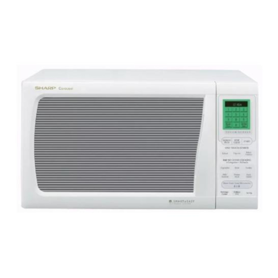
R - 340DK R -340DW SERVICE MANUAL S2008R340DPW/ MICROWAVE OVEN R-340DK MODELS R-340DW 12 : 30 PM Minute Kitchen PLus + Timer T O U C H . S C R E E N MINUTE STOP PLUS START CLEAR ONE TOUC H SENSO... -
Page 2: Precautions To Be Observed Before And During Servicing To Avoid Possible Exposure To Excessive Microwave Energy
Before servicing an operative unit, perform a microwave emission check as per the Microwave Measurement Procedure outlined in this service manual. If microwave emissions level is in excess of the specified limit, contact SHARP ELECTRONICS CORPORATION immediately @1-800-237-4277. If the unit operates with the door open, service person should 1) tell the user not to operate the oven and 2) contact SHARP ELECTRONICS CORPORATION and Food and Drug Administration's Center for Devices and Radiological Health immediately. -
Page 3: Warning To Service Personnel
R -340DK R-340DW WARNING TO SERVICE PERSONNEL Microwave ovens contain circuitry capable of pro- ducing very high voltage and current, contact with following parts may result in a severe, possibly fatal, electrical shock. (Example) High Voltage Capacitor, High Voltage Power Trans- former, Magnetron, High Voltage Rectifier Assem- bly, High Voltage Harness etc.. -
Page 4: Microwave Measurement Procedure
R- 340DK R-340DW MICROWAVE MEASUREMENT PROCEDURE A. Requirements: 1) Microwave leakage limit (Power density limit): The power density of microwave radiation emitted by a microwave oven should not exceed 1mW/cm at any point 5cm or more from the external surface of the oven, measured prior to acquisition by a purchaser, and thereafter (through the useful life of the oven), 5 mW/cm at any point 5cm or more from the external surface of the oven. - Page 5 MICROWAVE OVEN R-340DK/ R-340DW GENERAL INFORMATION FOREWORD This Manual has been prepared to provide Sharp Electronics Corp. Service Personnel with Operation and Service Information for the SHARP MICROWAVE OVEN, R-340DK, R-340DW. OPERATION It is recommended that service personnel carefully study the entire text of this manual so that they will be qualified to render satisfactory customer service.
-
Page 6: General Information
R- 340DK R-340DW SPECIFICATION ITEM DESCRIPTION Power Requirements 120 Volts / 14 Amperes 60 Hertz Single phase, 3 wire grounded Power Output 1150 watts (IEC TEST PROCEDURE) Operating frequency of 2450MHz Case Dimensions Width 20-1/2" Height 11-7/8" Depth 17-1/8" Cooking Cavity Dimensions Width 14-3/4"... - Page 7 R -340DK R-340DW contact a qualified electrician and have it replaced with a properly Grounded grounded three-pronged wall receptacle or have a grounding adapter Receptacle Box properly grounded and polarized. If the extension cord must be used, it should be a 3-wire, 15 amp. or higher rated cord. Do not drape over a countertop or table where it can be pulled on by children or tripped over 3-Pronged Plug...
-
Page 8: Operation
R- 340DK R-340DW OPERATION DESCRIPTION OF OPERATING SEQUENCE The following is a description of component functions during box, and then into the cavity where the food is placed to oven operation. be cooked. 5. Upon completion of the cooking time, the power OFF CONDITION transformer, oven lamp, etc. - Page 9 R -340DK R-340DW Note: The ON/OFF time ratio does not correspond with The 16 seconds is the cooling time required to remove the percentage of microwave power, because any vapor from the oven cavity and sensor. approx. 2 seconds are needed for heating of the NOTE: During this first stage, do not open the door or touch magnetron filament.
- Page 10 R- 340DK R-340DW SCHEMATIC NOTE: CONDITION OF OVEN. 1. DOOR CLOSED. 2. CLOCK APPEARS ON DISPLAY. NOTE: Indicates components with potential above 250 V. THERMAL MONITOR THERMAL CUT-OUT (OVEN) FUSE 20A CUT-OUT (MG.) N.O. POWER N.O. TRANSFORMER (RY-1) (RY-2) PRIMARY INTERLOCK RELAY CONTROL UNIT...
- Page 11 R -340DK R-340DW DESCRIPTION AND FUNCTION OF COMPONENTS DOOR OPEN MECHANISM CAUTION: BEFORE REPLACING A BLOWN MONITOR FUSE TEST THE DOOR SENSING SWITCH, The door is opened by pulling the door. Refer to the Figure PRIMARY INTERLOCK RELAY (RY2), RELAY D-1.
-
Page 12: Troubleshooting Guide
R- 340DK R-340DW TROUBLESHOOTING GUIDE Never touch any part in the circuit with your hand or an uninsulated tool while the power supply is connected. When troubleshooting the microwave oven, it is helpful to follow the Sequence of Operation in performing the checks. Many of the possible causes of trouble will require that a specific test be performed. -
Page 13: Test Procedure
R -340DK R-340DW CK = Check / RE = Replace RE RE A B C D E F F G H RE RE CK I CK CK CK J K L M N TEST PROCEDURE PROBLEM CONDITION Home fuse or circuit breaker blows when power cord is plugged into wall receptacle Monitor fuse blows when power cord... - Page 14 R- 340DK R-340DW TEST PROCEDURES PROCEDURE COMPONENT TEST LETTER MAGNETRON ASSEMBLY TEST 1. Disconnect the power supply cord, and then remove outer case. 2. Open the door and block it open. 3. Discharge high voltage capacitor. 4. To test for an open filament, isolate the magnetron from the high voltage circuit. A continuity check across the magnetron filament leads should indicate less than 1 ohm.
- Page 15 R -340DK R-340DW TEST PROCEDURES PROCEDURE COMPONENT TEST LETTER 8. Run the oven and check all functions. (HIGH VOLTAGES ARE PRESENT AT THE HIGH VOLTAGE TERMINAL, SO DO NOT ATTEMPT TO MEASURE THE FILAMENT AND HIGH VOLTAGE.) HIGH VOLTAGE RECTIFIER TEST 1.
- Page 16 R- 340DK R-340DW TEST PROCEDURES PROCEDURE COMPONENT TEST LETTER indicates overheating of the magnetron. Check for restricted air flow to the magnetron, especially the cooling fan air guide. 5. Reconnect all leads removed from components during testing. 6. Reinstall the outer case (cabinet). 7.
- Page 17 R -340DK R-340DW TEST PROCEDURES PROCEDURE COMPONENT TEST LETTER as follows. When the door is open, the meter should indicate a closed circuit. When the monitor switch actuator is pushed by a screw driver through the lower latch hole on the front plate of the oven cavity with the door opened (in this condition the plunger of the monitor switch is pushed in), the meter should indicate an open circuit.
- Page 18 R- 340DK R-340DW TEST PROCEDURES PROCEDURE COMPONENT TEST LETTER 3) Re-install the outer case (cabinet). 4) Reconnect the power supply cord after the outer case is installed. 5) Run the oven and check all functions. The following symptoms indicate a defective key unit. a) When touching the pads, a certain pad produces no signal at all.
- Page 19 R -340DK R-340DW TEST PROCEDURES PROCEDURE COMPONENT TEST LETTER unit and make sure the door sensing switch is closed (either close the door or short the door sensing switch connector). Use the Key unit matrix indicated on the control panel schematic and place a jumper wire between the pins that correspond to the STOP/CLEAR pad making momentary contact.
- Page 20 R- 340DK R-340DW TEST PROCEDURES PROCEDURE COMPONENT TEST LETTER WEIGHT 1ST STAGE 2ND STAGE LEVEL TIME LEVEL TIME 0.5lb 40sec. 30sec. (5) If improper operation is indicated, the control unit is probably defective and should be checked. FOIL PATTERN ON THE PRINTED WIRING BOARD TEST To protect the electronic circuits, this model is provided with a fine foil pattern added to the primary on the PWB, this foil pattern acts as a fuse.
- Page 21 R -340DK R-340DW TEST PROCEDURES PROCEDURE COMPONENT TEST LETTER 12) Re-install the outer case (cabinet). 13) Reconnect the power supply cord after the outer case is installed. 14) Run the oven and check all functions. AH SENSOR TEST Checking the initial sensor cooking condition WARNING : The oven should be fully assembled before following procedure.
- Page 22 R- 340DK R-340DW TEST PROCEDURES PROCEDURE COMPONENT TEST LETTER 9-6. The display will start to count down the remaining cooking time, and the oven will turn off automatically after the water is boiling (bubbling). If new sensor does not operate properly, the problem is with the control unit, and refer to explanation below.
-
Page 23: Touch Control Panel
R -340DK R-340DW TOUCH CONTROL PANEL ASSEMBLY OUTLINE OF TOUCH CONTROL PANEL 7) Indicator Circuit The touch control section consists of the following units. This circuit consists of 100 x 160 dots using a Liquid Crystal Display. The Liquid Crystal Display (LCD) is (1) Key Unit drived by IC5. - Page 24 R- 340DK R-340DW LSI(IXA029DR) The I/O signal of the LSI(IXA029DR) is detailed in the following table. Pin No. Signal Description TIOCA2 Terminal not used. Terminal not used. Power source voltage : +5.0V. The power source voltage to drive LSI is input to Vcc terminal. Connected to Vcc. TMO0 Signal to sound buzzer.
- Page 25 R -340DK R-340DW Pin No. Signal Description Key strobe signal. Signal applied to touch screen section. A pulse signal is input to PB1-PB5 terminal while one of G10 line keys on key matrix is touched. Oven lamp, fan motor and turntable motor driving signal 16.7 msec.
- Page 26 R- 340DK R-340DW Pin No. Signal Description Terminal not used. 75-76 MD0-MD1 Connected to VCC. Connected to GND. Avcc A/D converter power source voltage : +5V. The power source voltage to drive the A/D converter. Connected to VCC. Vref A/D converter power source voltage : +5V. The power source voltage to drive the A/D converter.
- Page 27 R -340DK R-340DW ABSOLUTE HUMIDITY SENSOR CIRCUIT (1) Structure of Absolute Humidity Sensor resistance balance of the bridge circuit is deviated to The absolute humidity sensor includes two thermistors increase the voltage available at AN6 terminal of the LSI. as shown in the illustration. One thermistor is housed in Then the LSI observes that voltage at AN6 terminal and the closed vessel filled with dry air while another in the compares it with its initial value, and when the comparison...
- Page 28 R- 340DK R-340DW TOUCH CONTROL PANEL SERVICING 1. Precautions for Handling Electronic Components 4) Re-install the outer case (cabinet). 5) Re-connect the power supply cord after the outer This unit uses CMOS LSI in the integral part of the case is installed. circuits.
-
Page 29: Component Replacement And Adjustment Procedure
WARNING FOR WIRING To prevent an electric shock, take the following pre- and Oven cavity. cautions. 3) Sharp edge: 1. Before wiring, Bottom plate, Oven cavity, Waveguide flange, 1) Disconnect the power supply cord. Chassis support and other metallic plate. -
Page 30: Pictorial Diagram
R- 340DK R-340DW CAUTION: 1. DISCONNECT OVEN FROM POWER SUP NOTE: When replacing the outer case, the 2 special PLY BEFORE REMOVING OUTER CASE. Torx screws must be reinstalled in the same 2. DISCHARGE THE HIGH VOLTAGE CA- locations. PACITOR BEFORE TOUCHING ANY OVEN COMPONENTS OR WIRING. - Page 31 R -340DK R-340DW to waveguide flange. 3. Insert the two (2) tabs of the chassis support to the oven 9. Lift up magnetron with care so that magnetron antenna cavity front plate and the back plate. is not hit by any metal object around antenna. 4.
- Page 32 4. Where the corners have been snipped off bend corner 7. Now the turntable motor is free. areas flat. No sharp edges must be evident after removal 8. After replacement use the one (1) screw to fit the of the turntable motor cover.
- Page 33 R -340DK R-340DW DOOR SENSING SWITCH/SECONDARY INTERLOCK SWITCH AND MONITOR SWITCH REMOVAL Re-install 1. Disconnect the power supply cord and remove outer case. 1. Re-install each switch in its place. The secondary 2. Open the door and block it open. interlock/monitor switches are in the lower position and 3.
- Page 34 R- 340DK R-340DW 11.Now, door panel with sealer film is free. 12.Tear sealer film from door panel. 13.Now, door panel is free. Upper Oven 14.Slide latch head upward and remove it from door frame Upper Hinge Oven Hinge with releasing latch spring from door frame and latch head.
- Page 35 R -340DK R-340DW...
- Page 36 R- 340DK R-340DW R2 91 1w R3 91 1w CN-A Q1 2SD1859 S1NB10 – AC120V 60Hz BZ/EN SP30 BUZZR OVEN LAMP OVEN LAMP FAN MOTOR FAN MOTOR TURNTABLE TURNTABLE MOTOR MOTOR MICRO MICRO (GREEN) SH-A DOOR SENSING SH-B DOOR SWITCH SENSING CN-C SWITCH...
- Page 37 R -340DK R-340DW...
- Page 38 R- 340DK R-340DW CN - C VRS1 (J1) CN - A QKITPB031MREO Figure S-5. Printed Wiring Board of Power Unit...
-
Page 39: Power Unit Circuit
Varistor (10G471K) VHEHZ161///-1 Zener diode (HZ16-1) 3- 2 DPWBFC041WRKZ CPU unit 3- 3 FPNLCB492WRKZ Control panel frame with key unit [R-340DK] 3- 3 FPNLCB495WRKZ Control panel frame with key unit [R-340DW] 3- 3-1 DUNTKA716WRKZ Key unit [R-340DK] 3- 3-1 DUNTKA717WRKZ... - Page 40 To have your order filled promptly and correctly, please furnish the following information. 1. MODEL NUMBER 2. REF. NO. 3. PART NO. 4. DESCRIPTION Order Parts from the authorized SHARP parts Distributor for your area. Defective parts requiring return should be returned as indicated in the Service Policy.
- Page 41 R - 340DK R -340DW OVEN AND CABINET PARTS 4-23 4-25 1-15 4-22 1-10 4-17 1-11 1-13 4-20 4-13 4-24 4-23 4-11 4-19 4-10 4-20 4-22 4-12 4-21 4-15 4-14 4-18 1-12 1-14 4-16 4-15...
- Page 42 R -3 40DK R-340DW CONTROL PANEL PARTS 3-3-1 DOOR PARTS MISCELLANEOUS (CAPACITOR) Actual wire harness may be different from illustration.
-
Page 43: Packing And Accessories
DOOR PROTECTION SHEET SPADPA204WRE0 PLASTIC BAG SSAKHA034WRE0 6- 8 INSTRUCTION BOOK & PRINTING MATTER 6- 2 TURNTABLE TRAY BOTTOM PAD ASSEMBLY FPADBA417WRKZ 6- 1 TURNTABLE SUPPORT TRAY PACK INTO THE SPADFA451WRE0 OVEN CAVITY Not replaceable items. PACKING CASE SPAKCD371WREZ [R-340DK] SPAKCD372WREZ [R-340DW]... - Page 44 No part of this publication may be repro- duced, stored in retrieval systems, or trans- mitted in any form or by any means, elec- tronic, mechanical, photocopying, record- ing, or otherwise, without prior written per- mission of the publisher. 2000 SHARP CORP. (1S2.530E) Printed in U.S.A...