Table of Contents
Advertisement
Quick Links
Advertisement
Table of Contents

Related Manuals for Sony DXC-D30F


Summary of Contents for Sony DXC-D30F
- Page 1 3-858-217-14(1) Color Video Camera Operating Instructions Before operating the unit, please read this manual thoroughly and retain it for future reference. DXC-D30F/D30PF DXC-D30K/D30PK DXC-D30L/D30PL DXC-D30H/D30PH © 1996 by Sony Corporation...
- Page 2 Record these numbers in the spaces provided below. Refer energy and, if not installed and used in accordance with the to them whenever you call upon your Sony dealer regarding instruction manual, may cause harmful interference to radio this product.
-
Page 3: Table Of Contents
Table of Contents Chapter 1 Overview Product Configurations ............ 7 Features ................8 Location and function of Parts ........11 Camera Head ..............11 VCL-916BYA Zoom Lens ..........17 DXF-701/701CE Viewfinder ..........19 Chapter 2 Fitting and Replacing the Lithium Battery ........21 Connection Fitting a VTR .............. - Page 4 Table of Contents Chapter 4 Viewfinder Screen Viewfinder Screen Indications ........45 Indications and Changing the Viewfinder Display ........45 Menus Viewfinder Normal Indications ........47 Status Indications .............. 50 Viewfinder Basic Menu ........... 51 Basic Menu Operations ............. 51 Contents and Settings of Each Page ........
- Page 5 Chapter 5 Adjustments and Settings for Special Cases ..........83 Settings Skin Detail Correction ............84 (Continued) Adjusting Color in the Specified Area ......84 Appendixes Important Notes on Operation ........85 Characteristics of CCD Sensors ........85 Warning Indications ............86 Specifications ..............
-
Page 7: Product Configurations
Product Configurations The eight models, DXC-D30F, DXC-D30K, DXC- and PAL versions and the components as shown in the D30L, DXC-D30H, DXC-D30PF, DXC-D30PK, figure below. The operation of the basic camera unit is DXC-D30PL, and DXC-D30PH, comprise both NTSC the same in all cases. -
Page 8: Features
Features -inch IT type Power HAD CCD Recording and managing setup data The DXC-D30/D30P Color Video Camera uses In addition to the setup menu that is displayed in the inch IT type Power HAD CCDs. It outperforms most viewfinder screen, the DXC-D30/D30P is equipped of the exiting FIT type CCD cameras for high-end use, with the following functions to facilitate camera head in both picture quality and sensitivity. - Page 9 Total level control system (TLCS) Dockable with various types of VTRs Even if the incoming light exceeds the range in which the standard auto iris can control exposure, the auto The DXC-D30/D30P docks with the DSR-1/1P gain control (AGC) or auto exposure (AE) backs up to DVCAM VTR to configure the DSR-130/130P digital ensure proper exposure.
- Page 10 Features Freeze mix function (when using DSR-1/1P) VTR data display The freeze mix function superimposes any previously recorded still picture on the viewfinder screen to When connected to a VTR, the DXC-D30/D30P is facilitate framing the subject when reshooting the able to display the following data on the viewfinder scene.
-
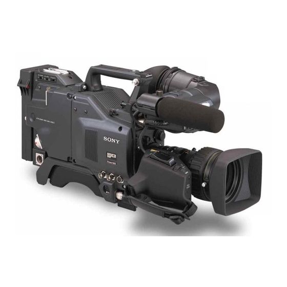
Page 11: Location And Function Of Parts
Location and Function of Parts Camera Head Right side view 1 EZ MODE button and indicator 2 EZ FOCUS button 3 EDIT SEARCH buttons 4 Slide cover lock !¢ REC TIME switch !∞ TTL RESET button !§ SKIN DTL switch TTL RESET !¶... - Page 12 Location and Function of Parts 1 EZ (“easy”) MODE button and indicator 5 A.IRIS (auto iris) MODE switch and indicator Depress this button (EZ mode on) when you want to When you use the auto iris function (by setting the iris be able to shoot immediately, with automatic selector on the lens to A), set this switch to suit the adjustment of the camera settings to standard values.
- Page 13 CAM/DL: This setting uses the DynaLatitude Note function, which finely adjusts the contrast of each The recording time displayed when this switch is set to pixel according to a histogram of luminance signal the TTL or DUR position is obtained by counting the levels.
- Page 14 Location and Function of Parts @º ZEBRA switch @¡ UP/ON button Set this switch to the ON position to display a zebra Use this button to open displays and to make “ON” pattern (diagonal stripes) in the viewfinder. settings. When using the advanced menus, use this Depending on the zebra setting in advanced menu page button to change menu pages or to switch to the 4, the zebra 1 for video levels between 70 to 90 IRE...
- Page 15 6 SHUTTER switch 8 AUDIO LEVEL knob Use this switch to set the shutter speed, CLS (clear When the DSR-1/1P is attached, you can use this knob scan), or EVS setting (see page 75). Usually, set this to manually adjust the channel 1 audio recording level. switch to OFF.
- Page 16 Use this connector to connect the switch for enabling Connect the lens connector. remote operation of the ClipLink function. !™ VF (viewfinder)connector (8-pin) For details of connectable switches, contact your Sony This is the connector for the DXF-40B/50B (or DXF- dealer. 40BCE/50BCE) viewfinder.
-
Page 17: Vcl-916Bya Zoom Lens
VCL-916BYA Zoom Lens 1 Focusing ring 6 Ff adjustment ring 7 MACRO button 8 MACRO ring 9 Zoom remote control connector 0 Focus remote control connector !¡ ZOOM selector 2 Manual zoom control 3 Iris ring !™ Power zoom switch !£... - Page 18 Location and Function of Parts 1 Focusing ring 7 MACRO button Turn this ring to focus the lens on the subject. For close-up work, hold this button down while turning the MACRO ring. (See page 82.) 2 Manual zoom control 8 MACRO ring For direct manual zoom control, set the ZOOM selector to the “M”...
-
Page 19: Dxf-701/701Ce Viewfinder
DXF-701/701CE Viewfinder 1 BATT indicator TALLY TAKE BATT 2 TAKE/TALLY indicator 3 REC/TALLY indicators 4 SHUTTER indicator SHUTTER GAIN UP 5 GAIN UP indicator 6 Eyepiece focusing knob 7 Accessory fixing screw hole 8 Tally lamp Microphone holding screw Eye cup Microphone holder Microphone 9 Eyepiece release catch... - Page 20 Location and Function of Parts 5 GAIN UP indicator (orange) This lights when the gain is 3 dB or more. 6 Eyepiece focusing knob Turn this to adjust the viewfinder focus to match your eyesight. (See page 79.) 7 Accessory fixing screw hole Attach optional video lights or other accessories here.
-
Page 21: Replacing The Lithium Battery
• Use only CR2032-type lithium batteries. Other types of lithium batteries may come loose when the camcorder is moved. If you have difficulty finding CR2032-type lithium batteries, contact your Sony dealer. Pull the upper part of the battery cover (on the rear of the camera head) forward and turn the cover clockwise. -
Page 22: Fitting A Vtr
Fitting a VTR When replacing the camera head grip with a camcorder This section explains how to attach the DSR-1/1P to grip, see “Using the Camcorder Grip” (page 23). the camera head. The method for attaching a PVV-3/ 3P is similar. Set the PRO 76-pin DIGITAL DSR-1/1P connector on the DSR-1/1P. -
Page 23: Using The Camcorder Grip
Tighten the two screws in the grip connector and the two screws in the shoulder pad section. Note Slide the shoulder pad to its central position before Screws tightening the screws. Otherwise the screws may not be properly fixed. To remove the VTR To fit a camera adaptor Reverse the fitting procedure. - Page 24 Fitting a VTR Remove the VTR connection plate. VTR connection plate Remove the DSR-1/1P’s shoulder strap fitting and the camera head connection plate. Camera head connection plate Shoulder strap fitting Perform the first three steps in “Fitting a VTR”. Screw the connection plate (supplied with the grip for the DSR-130/130P) which straddles the connection...
- Page 25 Attaching a camcorder grip to the PVV-3/3P Perform steps 2 to 4 in “Fitting a VTR”. If the viewfinder is attached, adjust the viewfinder to the full-forward position. For details, see “Adjusting the viewfinder position” on page 28. Remove the grip’s three screws, then pull up the grip to remove it.
-
Page 26: Fitting The Lens
Fitting the Lens In the case of the DXC-D30F/D30PF/D30K/D30PK model, the lens is already fitted. In other cases, use the following procedure to fit the lens. Remove the retaining rubber which prevents the lens mount from coming loose, then raise... - Page 27 Using the triangular mark as a guide, push the lens connector into the LENS connector on the camera head, until it clicks into place. Fasten the cable with the clamps. LENS connector Triangular mark If using a lens with a 6-pin connector Fitting optional filters This camera head has a 12-pin LENS connector.
-
Page 28: Using Accessories
Using Accessories Using the Viewfinder Removing the Viewfinder Remove any microphone from the viewfinder before beginning. VF connector Pull the viewfinder connector out of the VF connector on the front of the camera head. Loosen the viewfinder left-to- Retaining catch right position fixing ring, then Viewfinder left-to-right pulling up the retaining catch,... -
Page 29: Using An Optional Microphone
You cannot stow the camera attached with a left eye attach the CAC-12 Microphone Holder. adaptor in the LC-421 Carrying Case. For details, consult your Sony dealer. Using an Optional Microphone To use a long microphone such as the optional ECM-... - Page 30 Using Accessories Fitting an optional microphone Use the following procedure to attach an optional ECM-670 Microphone. Loosen the screw of the CAC- Microphone adaptor 12 Microphone Holder, then open the holder and replace the microphone adaptor with the one supplied with the ECM- 670 Microphone.
-
Page 31: Fitting To A Tripod
Fitting to a Tripod First fit the VCT-U14 Tripod Adaptor to the tripod, then mount the camera on the tripod adaptor. Adjusting the Shoulder Pad Position You can slide the shoulder pad toward the front or back by up to 10 mm from its central position (as when shipped). -
Page 32: Using The Carrying Case
Using Accessories Using the Carrying Case Stowing the camera Align the camera with the base of the case, and slide Align the camera with the base of the the camera in forward. carrying case. Checking that the pin at the rear engages correctly, push forward until it locks into place. -
Page 33: Connections
Camera cable • Select a camera cable to fit the camera input connector on the VTR you are using. • The maximum camera cable extent is 10 m (33 ft). For details, consult your Sony dealer. Chapter 2 Fitting and Connections... -
Page 34: Connecting A Number Of Cameras (Using A Camera Control Unit)
Control Unit to provide video and color sync between cameras, and special effects and other devices to allow For details, consult your Sony dealer. switching, wipes and so forth. Notes In the studio it may also be convenient to use a DXF- •... - Page 35 DXF-40B/40BCE or DXF-50B/50BCE DXC-D30/D30P CA-537/537P Headset VIDEO IN Headset INTERCOM TALLY/INTERCOM CAMERA (on the front) RETURN VIDEO IN CCU-M5/M5P Camera Control GEN LOCK IN Unit 75Ω To AC power supply termination DXF-40B/40BCE switch to OFF or DXF-50B/50BCE DXC-D30/D30P CA-537/537P Switcher, special Headset efects unit, etc.
-
Page 36: Connecting A Number Of Cameras (Without Using A Camera Control Unit)
Connections Connecting a Number of Cameras (Without Using a Camera Control Unit) signal. The camera will then operate synchronized to When using two or more synchronized cameras this signal. without a camera control unit, connect an external sync You can adjust the synchronization using the basic signal to the GEN LOCK IN connector on the camera menus. -
Page 37: Power Supply
130 minutes 140 minutes For details, consult your Anton Bauer products supplier or a) Requires the special-purpose DC-500 Battery Case. Sony dealer. Cannot be used with a camera adaptor. Battery low indications Using Battery Packs When the voltage of the supply to the camera head Always fully charge a battery pack before using it. -
Page 38: Camera Adaptor Power Supply
Power Supply Camera Adaptor Power Supply The camera adaptor automatically operates on power supplied to the VTR/CCU/CMA connector from the portable VTR, CCU-M7/M7P Camera Control Unit, CMA-8A/8ACE AC Adaptor or other connected device. Note Before use, check that the device connected to the VTR/CCU/CMA connector is able to provide the power required by the camera. -
Page 39: Basic Procedure For Shooting
Basic Procedure for Shooting ZEBRA switch Focusing ring POWER switch FILTER control VTR button RET button Check the switch settings on the camera head. Attach the VTR or camera adaptor to the camera (See pages 11 to 15.) head, then turn each device’s power on. If there is not sufficient time to check the camera settings, you can use “easy mode”... - Page 40 Basic Procedure for Shooting If required, switch on the center marker and/or Reviewing the recording safety zone (basic menu page 6 and advanced menu page 4) and zebra pattern (ZEBRA switch) It is possible to review the last few seconds of the in the viewfinder image.
-
Page 41: Shooting With The Dsr-1/1P
Shooting with the DSR-1/1P The DXC-D30/D30P docks with the DSR-1/1P to Press the VTR button on the camera head or the configure the DSR-130/130P DVCAM Digital lens. Camcorder. The following describes how to shoot using the DSR- The DSR-1/1P starts recording, and the REC/ 130/130P’s functions. - Page 42 Shooting with the DSR-1/1P Press the TAKE button when you find a shot Setting Mark IN/OUT points as you shoot where you would like to set a Mark OUT point. Instead of continuing shots from scene to scene, you The TAKE/TALLY indicator (orange) goes out in can specify Mark IN and Mark OUT points as you the viewfinder and the “TAKE”...
-
Page 43: Using The Edit Search Function While Back Space Editing
Setting cue points as you shoot Using the Edit Search Function While Back Space Editing You can make edit search operations easier by specifying cue points to highlight scenes. While the DSR-1/1P is in recording pause mode, press and hold the EDIT SEARCH buttons to activate the Perform steps 1 and 2 in “Using the ClipLink search playback function for as long as you hold down Function”... -
Page 44: Using The Freeze Mix Function
Shooting with the DSR-1/1P Release the REV or FWD button when you find Play back the tape on which the image to be used the tape location where you wish to continue for framework alignment has been recorded. shooting. For details of the playback operation, see the operating instructions for the DSR-1/1P. -
Page 45: Viewfinder Screen Indications
Viewfinder Screen Indications There are four types of indication screen which appear Status indications Display by holding the in the viewfinder, as follows. MENU/STATUS switch up • Normal indications while the normal indications are present. These show the operating state of the camera and : A U T O / A R S : S T D : S T D... - Page 46 Viewfinder Screen Indications immediately, move the cursor to the menu Displaying the advanced menu and number and then press the DOWN/OFF button. switching to the normal indications • To reinitialize all settings in the advanced menu to their factory defaults, press the UP/ON Use the following procedure to display the advanced button.
-
Page 47: Viewfinder Normal Indications
Viewfinder Normal Indications During normal operation, the following items can be indicated in the viewfinder. 1 VTR operation status indication !£ VTR warning indication a), b) a), b) 2 TAKE/CUE indication R E C T A P E N E A R E N D !¢... - Page 48 Viewfinder Normal Indications 5 Clip mode indication !¡ Audio recording level indicators A “CLIP M” or “CLIP C” indication appears when These show the recording levels of audio channels 1 you use the ClipLink function and record using the and 2 on the VTR. DSR-1/1P.
- Page 49 Only when connecting the DSR-1/1P Note Meaning Indication Depending on the lens being used, this indication may differ slightly from the actual f-stop on the lens. 50P CONNECT Connection with the PRO 50-pin connector on the DSR-1/1P. (Freeze mix function is disabled.) !•...
-
Page 50: Status Indications
O F F B A T T : 1 3 . 0 V If an error message appears, contact your Sony dealer. a) When both the DCC+ and DynaLatitude functions are set to OFF If using a VTR and an Anton Bauer Intelligent... -
Page 51: Viewfinder Basic Menu
DIAGNOSIS :ERROR ON button and the DOWN/OFF button at the same MEMORY:OK time. This error message “DISP ERROR” appears when the normal indications are displayed. If this message appears, contact your Sony dealer. Chapter 4 Viewfinder Screen Indications and Menus... - Page 52 Viewfinder Basic Menu Basic menu page 2 Basic menu page 3 mA.IRIS:±0 mS K I N D T L : 0 . 0 DTL LEV: ±0 D L L V L : S T D M.BLACK:±0 STRETCH:±0 SHUTTER:OFF Item Item Settings Settings A.
- Page 53 Basic menu page 5 Item Settings MARKER ON (normal value), OFF Sets MARKER display ON/OFF. MARKER is displayed This menu is displayed only when an external sync when this setting is ON signal is input to the camera adaptor or VTR connected and is not displayed to the camera head.
- Page 54 Viewfinder Basic Menu Basic menu page 7 M A R K / C U E : M A R K The following display is shown when the DSR-1/1P is F R E E Z E : O F F connected. C H G R E E L N O : Â...
- Page 55 Press the UP/ON button to select the required Basic menu pages 8 and 9 character. Each time you press the UP/ON button, the You can create a title of up to four lines, each of character cycles through the following sequence. twelve alphanumeric or punctuation characters, and then save it.
- Page 56 Viewfinder Basic Menu Press the UP/ON button once. The title is superimposed to the picture displayed on the viewfinder screen. Start shooting. To stop the title recording, press the MENU/ STATUS switch to clear the title display. Note on using the CCU-M5/M5P Camera Control Unit When the CCU-M5/M5P has a function switch setting of “TITLE ON”, the title display takes precedence, and the status display (see page 48) do not appear in the...
-
Page 57: Viewfinder Advanced Menu
Viewfinder Advanced Menu Bring up the advanced menu pages by setting the Advanced menu page 1 POWER switch to ON while pressing the UP/ON button up (see page 46). Use this page to return all advanced menu settings to There are up to 14 advanced menu pages (the number their factory preset values. - Page 58 Sets a baud rate for a DXF-701/701CE viewfinder computer connected to the is attached). REMOTE connector 1 (to be supported in future version). a) For more information about a connectable switch, contact your Sony dealer. Chapter 4 Viewfinder Screen Indications and Menus...
- Page 59 Advanced menu page 5 Advanced menu page 6 PAGE 5(NEXTm$ PREVm4) PAGE 6(NEXTm$ PREVm4) mSS IND:ALWAYS mAUDIO IND:ON LL IND:ON TAPE IND:ON MIC IND:ON TC IND:ON IRIS IND:ON ID IND:OFF GAIN IND:ON ID SET:µ FILTER IND:ON EXIT MENU (YESm4) EXIT MENU (YESm4) Item Item Settings...
- Page 60 Viewfinder Advanced Menu To set the camera ID Advanced menu page 7 Press the MENU/STATUS switch to move the cursor to ID SET. PAGE 7(NEXTm$ PREVm4) mEZ MODE:CUSTOM The cursor (→) changes to the text entry arrow (↓). A.IRIS-AGC:F2.8 A.IRIS-AE:F5.6 AGC LIMIT:18dB P A G E 6 ( N E X Tm$ P R E V m4) A.IRIS:STD...
- Page 61 EZ mode settings Advanced menu page 8 The following settings are set for the camera head when EZ mode has been selected. Item Setting P A G E 8 ( N E X Tm$ P R E V m4) CUSTOM C L O C K I N D : O F F mC L O C K S E T : ( S T A R Tm4) Setup file...
-
Page 62: Setup Files
Setup Files You can use setup files to reproduce a particular Move the cursor to SELECT FILE and use the UP/ configuration of settings. You can also revise the ON button or the DOWN/OFF button to select the contents of setup files. desired file. - Page 63 Press the UP/ON button to call up the file. To To call up files recorded onto a tape (when abort the call up operation, press the DOWN/OFF using the DSR-1/1P) button (the display returns to the one shown in step First, connect the DSR-1/1P to the camera head and load the cassette that contains the recorded files.
-
Page 64: Changing File Settings
Setup Files Page 11 Changing File Settings Settings Item When using advanced menu page 10 or 11, you can –99 to ±0 (normal value) to Adjusts the saturation of the change the settings about picture quality in setup files. image. Negative adjustment values (In basic menu page 2, a part of items are changeable.) decrease the saturation and... - Page 65 Access advanced menu page 12. PAGE12(NEXTm$ PREVm4) PAGE12(NEXTm$ PREVm4) FILE STORE FILE:*FILMLIKE FILE STORE DESTINATION FILE Currently FILE:*FILMLIKE USER2 selected file mDESTINATION FILE mSTORE FILE? USER1 DONE STORE FILE? (YESm4) EXIT MENU (YESm4) EXIT MENU (YESm4) a) An asterisk (*) appears in front of any factory To save setup files to a tape (when using preset file whose contents have been revised at the DSR-1/1P)
- Page 66 Setup Files Press the UP/ON button to store the file. To abort the save operation, press the DOWN/OFF button (the screen returns to the screen shown in step 2). The tape automatically rewinds and recording starts. The display changes as shown below, which includes color bars.
-
Page 67: Using Setupnavi And Setuplog With The Dsr-1/1P
Using SetupNavi and SetupLog with the DSR-1/1P The SetupNavi function records the setup menu and ”NO TAPE” is displayed if you neglected to load a setup files onto a tape, so that the same settings can be cassette. called up and used again or copied to another camera. The SetupLog function records a camera settings every Press the UP/ON button to call up the data few seconds at shooting and displays the recorded data... -
Page 68: Recording The Menu Settings Onto A Tape
Using SetupNavi and SetupLog with the DSR-1/1P The cursor (→) changes to the text entry cursor Recording the Menu Settings (↓). onto a Tape PAGE14(NEXTm$ PREVm4) Connect the DSR-1/1P and load the tape onto SETUP NAVI which the settings are to be recorded. Turn the CAMERAmTAPE camera power on. -
Page 69: Viewing Setuplog Data
To abort the data recording while in progress Status display (page 2) Press the DOWN/OFF button. P L A T C R 2 : 3 4 5 6 : After the data has been recorded, the following display P L O G 2 / 3 appears. -
Page 71: White Balance Adjustment
White Balance Adjustment Adjusting the white balance ensures that as lighting Make the following settings on the camera. conditions change white objects remain white in the • POWER switch: ON SAVE image and tones remain natural. • OUTPUT/DL/DCC+ switch: one of the CAM The color of light emitted varies from one light source positions to another, and as the lighting changes the apparent... -
Page 72: Using The Preset White Balance Settings
White Balance Adjustment The adjustment value is automatically saved in AUTO WHITE The color temperature is too low. Try -NG- the following, in this order of memory A or B as selected above. precedence. :C.TEMP.LOW (1) If the FILTER control is in position 2, CHG.FILTER To save the white balance adjustment for different 3 or 4, change it to position 1, then... -
Page 73: Light Sources And Color Temperatures
Light Sources and Color Using the ATW (Auto Tracing Temperature White Balance) Function Adjustment of the white balance to match the light The ATW function continuously adjusts the white source is essential to ensure correct color rendering. balance automatically to adapt to changes in lighting The color of a light source is indicated as a color conditions. -
Page 74: Black Balance Adjustment
-NG- position, and check that the OUTPUT/DL/DCC+ Close the iris and try again. If this fails, switch is in one of the CAM positions. consult your Sony dealer. TRY AGAIN BARS The camera is outputting a color bar Push the WHT/BLK switch in the BLK direction signal. -
Page 75: Shutter Settings
Shutter Settings This section covers the settings for electronic shutter speed, CLS (clear scan ) and EVS function. The new value for the shutter speed or clear scan frequency and EVS setting remains set until changed, even when the camera is powered off. Shutter speeds There are five shutter speeds, from s (DXC-D30) - Page 76 Shutter Settings When using the clear scan function Watching the monitor screen, adjust the frequency to give minimum interference. If there is a black band in the monitor image, reduce the frequency, and if there is a white band, increase the frequency. To return from the basic menu to the normal indications Press the MENU/STATUS switch as many times as...
-
Page 77: Setting The Clock And Timestamping Recordings
Setting the Clock and Timestamping Recordings Use advanced menu page 8 to set the camera head’s internal clock and record the date and time. PAGE 8(NEXTm$ PREVm4) CLOCK IND:OFF Note CLOCK SET:(STARTm4) If the following date/time setting procedure for the YY MM DD internal clock does not cause the date/time information 96 10 28... - Page 78 Setting the Clock and Timestamping Recordings Timestamping recordings You can timestamp recordings by superimposing the current date and time. Before shooting, set the CLOCK IND to CAM in advanced menu page 8. The date and time appear in the viewfinder, and are superimposed on the video signal output from the camera.
-
Page 79: Viewfinder Screen Adjustments
Using an optional part allows you to modify the adjustment range to –2 to +1 diopters or –0.5 to +3 diopters. For details, consult your Sony dealer........................................... 1) Diopter: A unit to indicate the degree of convergence or divergence of a bundle of rays. -
Page 80: Adjusting The Lens
Adjusting the Lens Flange Focal Length Adjustment It is necessary to adjust the flange focal length (the • When a lens is fitted for the first time distance from the lens flange to the plane of the image • After changing lenses along the optical axis) in the following cases. -
Page 81: Iris Adjustments
Iris Adjustments Iris ring Instant automatic iris button ZEBRA switch Iris selector A.IRIS MODE switch To make the image clearer when shooting a There are three ways of adjusting the iris: subject lit by a spotlight automatically, manually, and with the instant In the automatic iris adjustment mode, set the A.IRIS automatic iris adjustment function. -
Page 82: Macrophotography
Adjusting the Lens Macrophotography Use the macro function when the subject is less than about 90 cm (3 feet) (for the VCL-916BYA) from the front of the lens. It is possible to shoot close-ups down to a range of 10 mm (wide angle, f = 9 mm). ZOOM Bring the lens up to the subject so that the image is the required size. -
Page 83: Settings For Special Cases
Settings for Special Cases Settings for special cases Shooting conditions Setting Effect The background is very bright, and the Set the A.IRIS MODE switch to BACK L, This lightens the foreground. subject is too dark. turning the indicator on. The subject is under a spotlight. Set the A.IRIS MODE switch tp SPOT L, This prevents white burn-out in highlights turning the indicator on. -
Page 84: Skin Detail Correction
Settings for Special Cases Skin Detail Correction Adjusting Color in the Specified Area The DXC-D30/D30P provides an easy push-button function that designates an active skin tone area. You can adjust the specified color using setup files. Perform the same procedure with the skin detail correction to designate the target area . -
Page 85: Important Notes On Operation
In the event of operating problems If you should experience problems with the unit, contact your supplier or Sony service representative. Appendix... -
Page 86: Warning Indications
(During other fault in the heads, disconnect the recording only) the recording power and consult your Sony system. dealer. — — SERVO The servo Recording Disconnect the power and lock has continues, but consult your Sony dealer. -
Page 87: Specifications
Specifications Y/C separate signals DXC-D30/D30P Camera Head Y: 1.0 Vp-p, sync negative, unbalanced Imaging element Three-chip interline transfer CCD 768 (horizontal) × 494 (vertical) C: burst level 0.286 Vp-p, no Pixel resolution sync (DXC-D30) Video S/N ratio 63 dB (typical) (DXC-D30) 752 (horizontal) ×... -
Page 88: Related Products
(32 × 24 inches) Related Products Telephoto: 51 × 38 mm (2 × 1 inches) There is a range of Sony products available to meet Focusing range Infinity to 0.9 m every conceivable video shooting requirement. For Filter attachment threads details, consult your Sony sales representative or 77 mm dia., 0.75 mm pitch (on... - Page 89 Studio equipment CCU-M3/M3P/M5/M5P/M7/M7P Camera Control Unit SEG-2550A/2550AP Special Effects Unit CRK-2000/2000P Chroma Keyer WEX-2000 Wipe Pattern Extender DXF-50B/50BCE 5-inch Viewfinder (monochrome) DXF-40B/40BCE 4-inch Viewfinder (monochrome) DR-100 Intercom Headset RMM-1800 Rack Mounting Kit Cables and miscellaneous The suffix number on a cable part number indicates the length in meters: e.g.
-
Page 90: Chart Of Optional Components And Accessories
Chart of Optional Components and Accessories EC-0.5C2 Microphone Cable CCZ-A cable CCU-M7/M7P/M5/M5P Camera Control Unit ECM-690/672 and C-74 Microphone CCZ-A cable BVW-50/50P Betacam SP CAC-12 Microphone Holder CCZQ-A cable VO-8800/8800P U-matic CCZJ-A cable VHS VTR CA-537/ 537P Camera CCZ-A cable VA-5/5P + BVV-5/5PS Adaptor DXF-50B/50BCE/40B/... - Page 92 Sony Corporation Printed in Japan...