Table of Contents
Advertisement
Quick Links
Advertisement
Table of Contents

Summary of Contents for Samsung GEMS-H
- Page 1 GEMS‐H Instructions for Use ...
- Page 2 Publishing details GEMS‐H Powered Lower Extremity Exoskeleton, Instructions for use Document No.: SAIT‐IFU‐GEMS‐H Revision No.: 1.1 Revision date: 2019. 11. 05 Application version: 1.4 Manufacturer Samsung Electronics Co., Ltd. 129, Samsung‐Ro, Yeongtong‐Gu, Suwon‐Si, Gyeonggido, Republic of Korea, 16677 +82‐31‐8061‐1114 www.samsung.com Copyright This document is protected by copyright. All rights reserved. Notably, no portion of this publication may be ...
-
Page 3: Table Of Contents
Table of Contents Chapter 1. General .............................. 5 1.1. About these instructions for use .......................... 5 1.2. Explanation of symbols ............................. 5 Chapter 2. Introduction ............................. 6 2.1. Indications for use .............................. 6 2.2. Training .................................. 6 2.3. Safe environments .............................. 6 2.4. Intended user profile .............................. 7 2.5. Operating principle .............................. 7 2.6. Contraindications .............................. 7 Chapter 3. Safety .............................. 9 3.1. Symbols .................................. 9 3.2. Safety .................................. 10 3.3. Safety standards .............................. 12 3.4. Environmental conditions ............................ 13 3.5. Disposal .................................. 13 3.6. Patient environment ............................... 13 Chapter 4. Device description .......................... 14 4.1. Package contents .............................. 14 4.2. Device overview .............................. 16 4.3. Accessory: waist extension belt .......................... 17 ... - Page 4 6.2. Opening and closing the GEMS‐H application ...................... 31 6.3. Login screen ................................ 33 6.4. Overall GEMS‐H user interface .......................... 35 6.5. The ‘Patient Info’ tab .............................. 36 6.6. The ‘Device Connect’ tab ............................ 39 6.7. The ‘Device Control’ tab ............................ 40 6.8. Safety features ................................ 53 Chapter 7. Shutdown .............................. 59 7.1. Stop the assistance .............................. 59 7.2. Turn off the device .............................. 59 7.3. How to take off the device ............................ 60 Chapter 8. Maintenance ............................ 61 8.1. Storage ................................... 61 8.2. Regular maintenance (Weekly Checklist) ....................... 62 8.3. Cleaning .................................. 62 8.4. How to charge the GEMS‐H ............................ 63 Chapter 9. Troubleshooting ............................. 65 9.1. Troubleshooting .............................. 65 9.2. Device messages .............................. 66 Chapter 10. Technical specifications ......................... 70 10.1. Specifications ................................ 70 10.2. EMC (Electromagnetic Compatibility) ........................ 72 Chapter 11. Clinical studies ............................ 77 11.1. Introduction ................................ 77 11.2. Adverse events ...
-
Page 5: Chapter 1. General
Chapter 1. General 1.1. About these instructions for use These instructions for use provide the information necessary to operate the GEMS‐H device. PLEASE READ THESE INSTRUCTIONS FOR USE BEFORE OPERATING THE SYSTEM. If any part of these instructions for use is not clear, please contact Customer Support for assistance. 1.2. Explanation of symbols Safety notes Safety notes in these instructions for use are introduced with a symbol and a signal word to describe the severity of the hazard. ... -
Page 6: Chapter 2. Introduction
2.1. Indications for use The GEMS‐H is a robotic exoskeleton that fits orthotically on the wearer’s waist and thigh, outside of clothing. The device is intended to help assist ambulatory function in rehabilitation institutes under the supervision of a trained physical therapist for the following population: Individuals with stroke who have gait deficits and exhibit gait speeds of at least 0.4 m/s and are able to walk at least 10 meters with assistance from a maximum of one person. The trained physical therapist must successfully complete a training program prior to use of the device. The device is not intended for sports. 2.2. Training The GEMS‐H should be used only by medical personnel who have received specific training provided by Samsung, Inc. in the use of this device. Training provided by Samsung is limited to the use of the GEMS‐H and does not replace the necessary medical training and experience required to perform rehabilitation. 2.3. Safe environments The GEMS‐H is intended to be used under the supervision of a trained physical therapist in all use environments. Suitable use environments include: Hospital’s internal facilities (indoor only): a rehabilitation treatment room, hospital hallway, or gait analysis lab Surface type: smooth, cement, carpet, transitions, thresholds ... -
Page 7: Intended User Profile
Physical therapists • Earned a degree in physical therapy and obtained a current physical therapist license. Education • Familiar with the application of the tablet PC. Experience / • Be able to set up the Bluetooth communication between the device and the tablet PC. Abilities • Complete a training program provided by Samsung on how to use the device. 2.5. Operating principle GEMS‐H is a wearable powered exoskeleton that actively assists individuals to walk. The GEMS‐H consists of snap‐ together components weighing 4.7 lbs (2.1 kg) in total. The waist part houses two actuator modules, a Bluetooth module, and a control pack. Each actuator module houses a motor as well as an embedded angular position sensor and controller. In the control pack, there is a central processor, an IMU sensor, a rechargeable battery pack and a power switch. The GEMS‐H has the ability to assist wearers’ walking. The GEMS‐H has only one Walk Assist mode, which is operated based on the DOC (Delayed Output Control) algorithm. In the DOC algorithm, an on‐board microprocessor receives signals from integrated sensors which provide information on the patient’s joint angles. The sensors in the device ... - Page 8 For further information with regard to the clinical studies, refer to “Chapter 11. Clinical studies”. SAIT‐IFU‐GEMS‐H Rev.1.1 (2019‐11) Page 8 of 79...
-
Page 9: Chapter 3. Safety
Chapter 3. Safety 3.1. Symbols Symbol Meaning Serial number Manufacturer i nformation Manufacture date Type B applied part Follow instructions for use Non‐ionizing electromagnetic radiation Degree of protection against particulate matter Caution: Federal law restricts this device for sale by or on the order of a physician This mark is a Nationally Recognized Testing Lab (NRTL) marking and indicates conformance with UL 60601‐1. ... -
Page 10: Safety
3.2. Safety Risk of electrical shock hazard and performance degradation if this equipment is modified! Unauthorized modification of this equipment can affect the safety and effectiveness of the equipment. ‐ Do not modify this equipment without authorization of the manufacturer. Risk of serious injury due to misuse! Use of the device without training can result in serious injury to the patient. ‐ Users must successfully complete a training program provided by Samsung prior to use of the GEMS‐H. Risk of serious injury due to use of the device in improper environments! Use of the device in environments not recommended by the manufacturer may result in injury to the patient. ‐ Do not use in improper environments (e.g., on the sand, in stony areas, or any surface that is not recommended by manufacturer). Refer to section 2.3 Safe environments. Risk of serious injury to the patient who is distracted or cannot pay attention to tasks! ... - Page 11 Risk of serious injury to the patient due to loss of control! Should the therapist lose control of the device, or if a device is used without the supervision of the trained physical therapists, this may result in the patient having difficulty balancing and potentially falling while using the device. ‐ At least one therapist should monitor patients at all times while the devices are turned on and/or while the patients are walking. Risk of serious injury to the patient by potentially falling due to a device malfunction! Should the device malfunction, the 12 Nm torque provided by the device may suddenly stop. This may result in the patient having difficulty balancing, and potentially falling. ‐ In order to prevent malfunctions, users should make sure that the device has been maintained according to specifications and that the software is in working order prior to use. ‐ Users may conduct rehabilitation with a gait belt or a harness (e.g., body weight support system) and assistive devices such as cane or a walker as needed. Risk of serious injury to the patient due to improper fitting or fitting too tightly! Skin abrasions, including discomfort, skin pressure/friction, bruising, pain, or unusual swelling, may result from the device being improperly fitted or fitted too tightly. ‐ The device must be fitted over clothing to prevent skin abrasions. ‐ When putting on the device, the thigh support straps should be fitted with the knees slightly bent to avoid excessive tightening or pressing. ‐ Users should examine the discomfort and skin pressure of the patient. ‐ Care should be taken to avoid pinching skin when fitting the device. Risk of muscle soreness to the patient due to excessive rehabilitation! Should the patient perform dynamic and complex training at the first time of use, this may result in muscle soreness after the training session. ‐ Patients should start with simple activities, then increase the intensity of the training including more dynamic and complex activities. ...
-
Page 12: Safety Standards
Risk of injury to the patient and device damage due to sitting and leaning backward on a surface while wearing the device! If the patient wearing the device sits and leans back onto a surface (e.g., chair), it may cause discomfort, skin pressure, and/or device damage. ‐ Do not lean backward onto a surface while wearing the device and sitting. Risk of injury to the patient due to skin pressure! If the patient has something in their pockets or is wearing a belt while wearing the device, this may cause discomfort and pressure on the patient's body. ‐ Belts should be removed prior to putting on the device. ‐ Pockets should be emptied prior to putting on the device. Risk of potentially falling due to using discharged battery! Use of the device with a low battery may result in the device may suddenly turning off during rehabilitation which stops the assistive force. This may result in the patient having difficulty balancing and potentially falling. ‐ To ensure continuous power during use, always charge the battery at the end of each training session. ‐ When the battery level is below 20 %, charge the battery within 5 minutes. Risk of electrical shock hazard and performance degradation when the device is dropped! Should the device be dropped during use, it can affect the safety and effectiveness of the equipment. ‐ Stop using it immediately and report the situation to the manufacturer. 3.3. Safety standards The GEMS‐H conforms to the following international standards: • IEC 60601‐1:2005+A1:2012 • IEC 60601‐1‐2:2014 • IEC 60601‐1‐6:2010+A1:2013 •... -
Page 13: Environmental Conditions
3.4. Environmental conditions Operation Storage & Transport Temperature 32 ℉ to 86 ℉ (0 ℃ to 30 ℃) ‐ 77 ℉ to 158 ℉ (‐ 25 ℃ to 70 ℃) Humidity 30 to 85 % (non‐condensing) 10 to 94 % (non‐condensing) Pressure 700 hPa to 1060 hPa 500 hPa to 1060 hPa 3.5. Disposal This device contains electrical and electronic equipment waste, which must be disposed of separately from unsorted municipal waste. Please contact the manufacturer or an authorized disposal company to decommission your equipment according to local regulations. 3.6. Patient environment Part within the patient environment Device, Tablet PC Part outside the patient environment Device charger, Tablet PC charger ... -
Page 14: Chapter 4. Device Description
Chapter 4. Device description 4.1. Package contents The GEMS‐H sales package contains the following items: Waist part (Sizes: S, M, L) Thigh support frame (Sizes: S, M) Thigh support strap with buckles (Sizes: S, M, L) Tablet PC Tablet PC case Device charger Tablet PC charger Hip width ruler Extension belt Torque wrench Storage case Instructions for use Depending on the wearer’s size, these components are used in combination. For safe storage, place the GEMS‐H in the case after each use. Waist part (Sizes: S, M, L) Thigh support frame (Sizes: S, M) – left/right Thigh support strap with buckles (Sizes: S, M, L) – Tablet PC left/right SAIT‐IFU‐GEMS‐H Rev.1.1 (2019‐11) ... - Page 15 Device charger Tablet PC charger Hip width ruler Extension belt Torque wrench Storage case Tablet PC case (optional) Instructions for use SAIT‐IFU‐GEMS‐H Rev.1.1 (2019‐11) Page 15 of 79...
-
Page 16: Device Overview
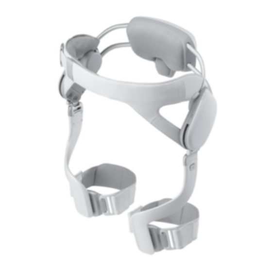
4.2. Device overview No. Parts Description 1 Control pack Computing unit and built‐in battery 2 Battery Power supplier 3 Power switch Power ON/OFF switch (switch up: ON, switch down: OFF) 4 Waist belt Waist belt 5 Actuator module Motor and reduction gears for generating the assistive force 6 Thigh support frame Rigid frame delivering the assistive force to the wearer’s thigh 7 Thigh support strap Fastening strap connecting the thigh support frame and to the wearer’s thigh SAIT‐IFU‐GEMS‐H Rev.1.1 (2019‐11) Page 16 of 79... -
Page 17: Accessory: Waist Extension Belt
4.3. Accessory: waist extension belt The extension belt may be used to increase the length of the waist belt by 5.9 inches (150 mm). It is used when the waist belt of the device is too short to fasten completely and comfortably around the patient’s waist. 4.4. Accessory: thigh support frame Small size Medium size Length, inches (mm) 9.1 (230) 10.0 (255) SAIT‐IFU‐GEMS‐H Rev.1.1 (2019‐11) Page 17 of 79... -
Page 18: Accessory: Thigh Support Strap
4.5. Accessory: thigh support strap Small size Medium size Large size Length, inches (mm) 14.2 (360) 16.1 (410) 17.7 (450) SAIT‐IFU‐GEMS‐H Rev.1.1 (2019‐11) Page 18 of 79... -
Page 19: Marking Plate
4.6. Marking plate SAIT‐IFU‐GEMS‐H Rev.1.1 (2019‐11) Page 19 of 79... -
Page 20: Chapter 5. Preparation
Chapter 5. Preparation 5.1. Device fitting procedure ① Measure the wearer’s hip width using the provided hip width ruler. ② Select the appropriate waist part size according to the wearer’s hip width. hip width: 12.4 ~ 14.4” (315 ~ 365 mm) Small hip width: 14.0 ~ 15.9” (355 ~ 405 mm) Medium hip width: 15.9 ~ 17.9” (405 ~ 455 mm) Large ③ Use the torque wrench provided to adjust the waist part width according to the wearer’s hip width. Details of the waist part adjustment are shown in section 5.3 Adjust the waist part width. ④ Use the extension belt if the length of the waist belt is too short. The extension belt may be used to increase the length of the waist belt by up to 5.9 inches (150 mm). ⑤ Use a Medium‐size thigh support frame initially. If the thigh support frame area comes in contact with the knee cap, then use the Small‐size thigh support frame. ⑥ Use the thigh support strap size which fits the wearer’s thigh. Choose the strap size adequately, so that the Velcro can be securely fastened. SAIT‐IFU‐GEMS‐H Rev.1.1 (2019‐11) Page 20 of 79... -
Page 21: Determine The Waist Part Size
5.2. Determine the waist part size 5.2.1. Waist part size The device width can be adjusted within a range of about 2 inches (50 mm) by adjustment of the waist part. Small [inches (mm)] Medium [inches (mm)] Large [inches (mm)] Hip width 12.4 ~ 14.4 (315 ~ 365) 14.0 ~ 15.9 (355 ~ 405) 15.9 ~ 17.9 (405 ~ 455) Waist depth 5.7 ~ 6.7 (145 ~ 170) 7.9 ~ 9.8 (200 ~ 250) 9.4 ~ 12.2 (240 ~ 310) Waist circumference 30.7 ~ 34.3 (780 ~ 870) 32.3 ~ 36.2 (820 ~ 920) 36.2 ~ 43.3 (920 ~ 1100) SAIT‐IFU‐GEMS‐H Rev.1.1 (2019‐11) Page 21 of 79... - Page 22 5.2.2. Hip width measurement When the measured hip width falls between the applicable size ranges of two different devices, it is recommended that the device of the bigger size be selected. A 10 mm margin of safety is automatically included on each side by the hip width ruler provided, as shown below, and is usually suitable if the measurement is taken loosely. If the device is still too tight, the user should adjust the device for patient comfort at their discretion. ① Identify the hip joint location. ② Measure the hip width using the ruler provided, as shown above. ③ Select the waist part size which fits the wearer’s hip width. hip width: 12.4 ~ 14.4” (315 ~ 365 mm) Small hip width: 14.0 ~ 15.9” (355 ~ 405 mm) Medium hip width: 15.9 ~ 17.9” (405 ~ 455 mm) Large SAIT‐IFU‐GEMS‐H Rev.1.1 (2019‐11) Page 22 of 79...
-
Page 23: Adjust The Waist Part Width
5.2.3. Size markings The size of the waist part is indicated on the front clasp (S, M, and L). 5.3. Adjust the waist part width Property damage when the screws are over tightened! The product may be damaged if the screws are over tightened or continuously tightened after clicking sounds are emitted from the torque wrench provided. ‐ Do not tighten further after clicking sounds emit from the torque wrench provided. Property damage when the screws are not fully tightened! If the screws are not fully tightened, the screws will be too loose during walking and the waist part may be damaged. ‐ Before putting the device on the patient, check that the screws are tightened securely enough that noise is not made, as the screws loosen during walking. ① Ensure the Velcro on the waist belt is unfastened. ② Adjust the device width by loosening the two screws, one on each side of the control pack. SAIT‐IFU‐GEMS‐H Rev.1.1 (2019‐11) Page 23 of 79... -
Page 24: Wear The Waist Belt & Fasten Thigh Support Frames
③ Use the provided torque wrench to loosen both screws. Turn counter‐clockwise (CCW) to loosen. ④ Check the ruler scale on the upper beams (metric‐based, one tick mark indicates 10 mm), and adjust the width by holding the lower beams and applying a gentle force. ⑤ Once the waist part has been adjusted to the appropriate size, use the provided torque wrench to tighten (turn clockwise) the screws until the wrench clicks. 5.4. Wear the waist belt & fasten thigh support frames Risk of serious injury due to improper device sizing to the patient! Improper sizing of the waist part and thigh support frames could cause skeletal fractures and injury to the patient. ‐ The therapists must determine the proper size of the waist part and thigh support frames to suit the patient. ... - Page 25 Risk of potentially falling due to the loosened waist belt! If the device is used frequently, Velcro on the waist belt may lose its adhesion. If the patient wears the thigh support strap loosely during rehabilitation, this may result in the patient having difficulty balancing, and potentially falling. ‐ Check whether the waist belt is fastened before walking. Risk of potentially falling due to loosening the thigh support frame during walking! When the therapist attaches the thigh support frames loosely, the thigh support frames may be disconnected during walking. This may result in the patient having difficulty balancing, and potentially falling. ‐ Make sure that the thigh support frame fastening hook is securely fastened before walking. (Check whether the release button had popped out and also try pulling out the thigh support frame) ...
-
Page 26: Fasten Both Thigh Support Straps
⑥ Use a Medium‐size thigh support frame initially, and use a Small‐size if the length of the wearer’s thigh is somewhat short (i.e., if the thigh support frame comes in contact with the knee cap). ⑦ The size is indicated on the release button of the thigh support frame (S, M). 5.5. Fasten both thigh support straps Risk of serious injury to the patient due to excessive tightening! Excessive tightening may cause discomfort, skin pressure/friction, bruising, pain, or unusual swelling caused by the exoskeleton which has the potential to lead to skin breakdown or abrasions. ‐ When putting on the device, the thigh support straps should be fitted with the knees slightly bent to avoid excessive tightening or pressing. ‐ The therapist should check for discomfort and check the skin pressure of the patient. Risk of falling due to broken buckle! If you insert the buckle while pulling sideways, the buckle may be broken. This may result in the patient having difficulty balancing, and potentially falling. ‐... - Page 27 The therapist can use a different size selection for the waist part, thigh support frame, and thigh support strap for each patient. For example, the therapist can select the Medium waist part, the Small thigh support frames, and the Large thigh support straps, and so on. ① Use a Medium‐size thigh support strap initially. Switch to Small or Large‐size if needed. ② Fasten both thigh support straps by attaching the buckles on the strap to the thigh support frame. ③ Make sure the strap Velcro is securely fastened around the wearer’s leg. Here is how to connect the strap with buckles. SAIT‐IFU‐GEMS‐H Rev.1.1 (2019‐11) Page 27 of 79...
-
Page 28: Waist Part Position
5.6. Waist part position Risk of serious injury due to incorrect waist part positioning! Incorrect waist part positioning on the patient could cause discomfort, skin pressure/friction, bruising, pain, or unusual swelling. ‐ Before turning the device on, ask the patient to walk in place to check for any discomfort. If so, reposition the device or try donning the device again. The therapist may need to re‐adjust the waist part width or the tightness of the waist belt. Examples of correct and incorrect waist part positioning: • The rotation axis of the actuator should align with the greater trochanter. • The control pack should rest directly below the lumbar curve near the sacrum. Examples of correct and incorrect thigh support frame positioning: SAIT‐IFU‐GEMS‐H Rev.1.1 (2019‐11) Page 28 of 79... -
Page 29: Check Prior To Use/Operation Of The Device
5.7. Check prior to use/operation of the device 5.7.1. Check for before use ① Check that the screws for adjusting the hip width of the waist part are not loose. ② Check that the thigh support frame fastening hook and strap Velcro are securely fastened. ③ Use the device after it is fully charged. Monitor the battery level and if the battery level is below 20 %, charge the device before use. 5.7.2. Check for any discomfort while walking ① Before turning the device on, make the wearer walk around to check for any discomfort. If there is discomfort, reposition the device or try donning the device again. You may need to readjust the width of the waist part or the waist belt tightness. ② Confirm with the patient that there is no pinching of the skin. If the patient is comfortable then the measurement is acceptable. ... -
Page 30: Chapter 6. Operating The Device
Chapter 6. Operating the device 6.1. Turn on the device Turn on the power switch by pushing it up. The indicator light (Power LED) will turn green. Then check that the front left and right LEDs (Control LED) are ON, which indicates that the device is booting up. This may take up to 15 seconds. When device is ready for operation, only the orange light is on. Sequence of LED (control LED and power LED) Lighting Situation LED state Example 1) Power off Both light off Control LED 2) Power on Power light on ... -
Page 31: Opening And Closing The Gems-H Application
6.2. Opening and closing the GEMS‐H application 6.2.1. Opening the GEMS‐H application An android application controls and monitors the GEMS‐H using Bluetooth communication. Press the “GEMS‐H” icon on the home screen of the tablet PC to execute the application and it will show the login screen. SAIT‐IFU‐GEMS‐H Rev.1.1 (2019‐11) Page 31 of 79... - Page 32 6.2.2. Closing the GEMS‐H application If you want to close the application, 1) Press the “Recent apps” button at the bottom left of the home screen, as shown below. 2) Press the “Close all” button. If the user does not close the application properly, the following message will appear when the application is run again. Please press the “RESTART” button to start the application anew, or press the “CONTINUE” button to continue using the current application. SAIT‐IFU‐GEMS‐H Rev.1.1 (2019‐11) Page 32 of 79...
-
Page 33: Login Screen
6.3. Login screen The user and the administrator passwords should be managed by the authorized administrator. In particular, the administrator password should not be exposed to patients and non‐administrators. 6.3.1. Logging in ① A physical therapist may use the app as a general user by using a password given by an administrator. ② Administrators can change the user password with admin password in order to manage authorized users. 6.3.2. Changing the user and admin password The initial admin password will be given by the manufacturer, and the administrator can later change the password as needed. If you forget the admin password, you will need to contact the manufacturer to reinstall the application, which will erase your stored patient information. SAIT‐IFU‐GEMS‐H Rev.1.1 (2019‐11) Page 33 of 79... - Page 34 ① Click “Change password”. ② Enter the admin password. ③ Select “user” or “admin” and save the new password. SAIT‐IFU‐GEMS‐H Rev.1.1 (2019‐11) Page 34 of 79...
-
Page 35: Overall Gems-H User Interface
6.4. Overall GEMS‐H user interface 1) Patient Info Tab User interface to manage patient information (See section 6.5 The ‘Patient Info’ tab for details). 2) Device Connect Tab User interface for connecting the device using Bluetooth (See section 6.6 The ‘Device Connect’ tab for details). 3) Device Control Tab User interface to control the device (See section 6.7 The ‘Device Control’ tab for details). SAIT‐IFU‐GEMS‐H Rev.1.1 (2019‐11) Page 35 of 79... -
Page 36: The 'Patient Info' Tab
6.5. The ‘Patient Info’ tab Be sure to ask the patient whether the information is correct or not. Select the patient ID from the list and load the information accordingly. Give a new patient ID for the first‐time patients and specify name, gender, age, height, weight, and note associated with a patient ID. Patient information is only for user reference and does not affect any functions of the device. Therefore, input of patient information can be skipped. SAIT‐IFU‐GEMS‐H Rev.1.1 (2019‐11) Page 36 of 79... - Page 37 Press the “SAVE” button to save the patient ID and associated patient information. If you use a patient ID that already exists, all previous information will be updated with the new information. Press the “DEL” button to delete patient ID and associated information. SAIT‐IFU‐GEMS‐H Rev.1.1 (2019‐11) Page 37 of 79...
- Page 38 Uncheck “Unit (US)” in order to use SI Units instead of US Units. SAIT‐IFU‐GEMS‐H Rev.1.1 (2019‐11) Page 38 of 79...
-
Page 39: The 'Device Connect' Tab
6.6. The ‘Device Connect’ tab ① Check the device name on the top of the clasp. ② Select the name of the device to enable so that it is highlighted in yellow. Press the “SCAN” button again if the desired device is not found. ③ Connect the selected device by pressing the “CONNECT” button. message will appear and the text on the button will changed to “DISCONNECT”. SAIT‐IFU‐GEMS‐H Rev.1.1 (2019‐11) Page 39 of 79... -
Page 40: The 'Device Control' Tab
6.7. The ‘Device Control’ tab The screen configuration of the ‘Device Control’ tab is shown below. SAIT‐IFU‐GEMS‐H Rev.1.1 (2019‐11) Page 40 of 79... - Page 41 6.7.1. Monitoring area 1) Monitoring option Device and patient information may be monitored as a graph or as text. Press the “Monitoring Option” button to open the “Monitoring Option Screen”. In the monitoring option screen, the user may select data to be displayed on the main screen graphically or textually. These selections may be made by checking “Graph” or “Text” in the relevant row of the monitoring option screen. The “MAX” column shows the graph range for each monitoring data. The default settings of the monitoring option screen are shown below / above. SAIT‐IFU‐GEMS‐H Rev.1.1 (2019‐11) Page 41 of 79...
- Page 42 ① The “Max” label on graph view refers to the max value in the monitoring option screen as shown below: ② Legend of selected data as shown below: ③ The following table explains the meaning of the possible monitoring data variables: JointAngL left hip joint angle JointAngR right hip joint angle JointVelL left hip joint angular velocity JointVelR right hip joint angular velocity JointTrqL left hip assist torque, measured JointTrqR right hip assist torque, measured ImuEulerX Euler angle of X axis from the IMU sensor ImuEulerY Euler angle of Y axis from the IMU sensor ImuEulerZ Euler angle of Z axis from the IMU sensor SAIT‐IFU‐GEMS‐H Rev.1.1 (2019‐11) Page 42 of 79...
- Page 43 ImuGyroX angular velocity of X axis from the IMU sensor ImuGyroY angular velocity of Y axis from the IMU sensor ImuGyroZ angular velocity of Z axis from the IMU sensor ImuAccX acceleration of X axis from the IMU sensor ImuAccY acceleration of Y axis from the IMU sensor ImuAccZ acceleration of Z axis from the IMU sensor LeftButton currently not available RightButton currently not available ControlTrqL left hip torque goal from the algorithm ControlTrqR right hip torque goal from the algorithm Description of monitoring data 2) Monitoring Stop If you want to look at the graph in detail, you can freeze the monitoring data by pressing the “Monitoring Stop” button and zoom in on the graph. ...
- Page 44 4) Text Screen [Patient Info] Patient ID and name. [Device Info] Device ID, time duration since power on and battery level. [Mod e ] SAIT‐IFU‐GEMS‐H Rev.1.1 (2019‐11) Page 44 of 79...
- Page 45 6.7.2. Assist control area 6.7.2.1. Set the stand pose Make sure that hip angle is as close to neutral as possible with the patient standing naturally. If the patient is walking with their back bent, their neutral posture will also be standing with back bent. Incorrect setting of the stand pose may cause uncomfortable assistance or degrade clinical effectiveness. Make sure that both the left and right joint angle options are selected within the monitoring option dialog. ① Reset the hip angle sensor while the patient is standing in a neutral posture with hips straight if possible, or with comfortable posture otherwise. This will be used as the reference position for calculating flexion and extension. ② Press the “Set Stand Pose” button to reset the hip angle to zero and to calibrate the reference posture. ③ If the stand pose is not set, the “START” button will not be activated. ④ Make sure that both left the right joint angles are selected in the monitoring option dialog to see both joint angles in the graph. ...
- Page 46 6.7.2.2. Set assist mode ① By pressing the “Set Assist Mode” button, the therapist can change the assist mode and parameters. ② At present, only the Walk Assist mode is provided. ③ Pre‐saved assist parameters can be selected. The default parameters are available as “Normal,” and an additional saved parameter set called “Strong” is available by default. ④ Assist parameters can be saved with a user‐defined name using the “Save” button. ⑤ Parameters that are no longer needed can be deleted with the “Del“ button. The default parameters cannot be deleted. ⑥ Select the “log” check box to automatically log data when the assist starts. If you are interested in using your log data for research or other purposes, please contact the manufacturer. SAIT‐IFU‐GEMS‐H Rev.1.1 (2019‐11) Page 46 of 79...
- Page 47 6.7.2.3. Start/Stop assistance 1) Start assistance ① Press the “START” button to run the assistance algorithm. ② If the algorithm runs properly, the tablet PC interface and the LEDs on the device will change as shown below. 2) Stop assistance ① Press the “STOP” button to stop the assistance algorithm. ② If the algorithm stops properly, the tablet PC interface and LEDs on the device will change as shown below. SAIT‐IFU‐GEMS‐H Rev.1.1 (2019‐11) Page 47 of 79...
- Page 48 6.7.3. The parameter control area 6.7.3.1. Parameter control descriptions The parameter control area contains a number of parameters that can be controlled by the user while therapy is in progress. The following illustrations and table describe the use of the parameter control area. Assist pattern changes by controlling parameters SAIT‐IFU‐GEMS‐H Rev.1.1 (2019‐11) Page 48 of 79...
- Page 49 Parameter GUI element Function Adjust assist strength to be weak or strong. Gradually increase the gain after confirming that the torque is not too strong for the wearer. Each press will change the parameter by 0.2. This parameter ranges from 0 to 15. The default setting is 7 and usually assists around 5 Nm. ...
- Page 50 Parameter GUI element Function GainL +/‐ Adjust assist strength of left leg only. GainR +/‐ Adjust assist strength of right leg only. Turn off joint limit monitor (extension 40 degree ~ flexion 100 Disable Joint Limit degree) which is used for safety functions. Free The device gives no assistive force, and moves itself just enough to Motion follow the patient as the patient moves. Lock Disable all buttons to prevent accidental button presses. Buttons Reset Reset all assist parameters back to initial values of the START point. Params 6.7.3.2. Parameter control monitoring The therapist can monitor the control parameters and assist torque. ...
- Page 51 1) Control parameters: Gain, Delay parameters As shown in the figure below, the user can monitor parameter adjustments. If a parameter is adjusted beyond the defined parameter range, the parameter will not change. 2) Monitor parameter: Maximum Torque Parameters (MaxTrqL, MaxTrqR) Users can monitor the maximum assistive torques that the device delivers to the patient as the user changes the assist gain. The maximum assistive torques MaxTrqL and MaxTrqR indicate the maximum values of assistive torques provided by the device for the last two steps. Even with parameters fixed, the assistive strength will vary based on the patient walking condition such as step length, walking speed, and other factors. SAIT‐IFU‐GEMS‐H Rev.1.1 (2019‐11) Page 51 of 79...
- Page 52 6.7.3.3. Example of parameter control SAIT‐IFU‐GEMS‐H Rev.1.1 (2019‐11) Page 52 of 79...
-
Page 53: Safety Features
6.8. Safety features 6.8.1. Mitigation of risks related to a fully discharged Lithium Ion battery The Li‐ion battery used in this device has a risk of explosion and of material leakage when completely discharged. To prevent this, the power control module (PCM) circuit is designed to fundamentally cut off the power before the battery discharges fully. In addition, the battery level is continuously measured and displayed on the application. Status of the device and recommended user action An alert will appear on the associated tablet PC if the battery level is below 20 % and 10 %, and the battery level will be shown in red. When the battery level is below 20 %, the physical therapist is recommended to charge the battery within 5 minutes. When the battery level is below 10 %, it is recommended that device operation be stopped immediately, and that the device be charged before further use. As a final warning, if the battery level is almost zero, then without further warning messages, the low battery warning sound will be played from the device speaker, and device assistance will be stopped immediately. ... - Page 54 Error message examples SAIT‐IFU‐GEMS‐H Rev.1.1 (2019‐11) Page 54 of 79...
- Page 55 6.8.2. Mitigation of risks due to excessive power output In order to avoid an excessive torque being applied to the patient, the device is designed to not to transmit a torque of more than 12 Nm ±15 % to the patient. When the assistive force reaches the predetermined maximum force, then the device will cease applying the assistive force. Status of the device and recommended user action: If assistive force is ceased due to an over‐torque situation, the associated tablet PC will display an error message of “EXCEEDED TORQUE LIMIT.” When this message is displayed and the device is stopped, the physical therapist may try to start the device again by pressing the “START” on the tablet PC. If the problem persists, reboot the device and the tablet PC. If there is still the problem with the device, turn off the device immediately and contact the manufacturer. Error message examples SAIT‐IFU‐GEMS‐H Rev.1.1 (2019‐11) Page 55 of 79...
- Page 56 6.8.3. Mitigation of risks due to excessive joint angle movement The GEMS‐H joints have mechanical stoppers to restrict over‐extension of joints, as well as software limits on joint movement. The mechanical stoppers are designed to ensure that the hip joints stay within the specified range even in the case of a malfunctioning device. The mechanical stoppers are set to a maximum of 110 degrees for flexion and a maximum of 45 degrees for extension. The delayed output controller (software) is limited to a maximum of 100 degrees for flexion and a maximum of 40 degrees for extension in normal use. Status of the device and recommended user action: When the joint angle reaches the joint angle limit, the device alerts the physical therapist by displaying a warning message of “EXCEED JOINT LIMIT”. When the joint angle reaches these joint limits, the device ceases applying assistive force. Thereafter, the physical therapist may reset the device by asking the patient to stand with upright posture and tapping the “Set Stand Pose” button on the tablet PC. Pressing the “START” button will then cause the ...
- Page 57 6.8.4. Mitigation of risks due to disconnection from the tablet PC When using the GEMS‐H, status monitoring and operation are done through a tablet PC via Bluetooth wireless communication. If the Bluetooth communication is interrupted, the monitoring and control of the GEMS‐H are designed to cease, but the device will continue operation. Status of the device and recommended user action: In the case that communication ceases, the tablet PC alerts the physical therapist by displaying the “DISCONNECTED” warning message on the application. For safety, when such an event occurs, the GEMS‐H continues at the current assistance setting. The physical therapist should stop the current treatment and reconnect the tablet PC. When the tablet PC is reconnected to the GEMS‐H, ...
- Page 58 6.8.5. Mitigation of risks due to abnormal actuator module status If the actuator module does not work properly during use, the controller may generate abnormal power. The actuator module is monitored continuously during treatment, and when an abnormality is detected, the assistive force is turned off. Status of the device and recommended user action: Should abnormal actuator status be detected, the tablet PC will display the error “DETECTED ABNORMAL ACTUATOR” The actuator status is considered abnormal when data transmitted from the actuator does not match the expected signals, for example, when the device detects patient movement, but actuator readings are constant. This may result from disconnected communication lines, actuator faults, and/or software failure. The physical therapist should attempt to fix the problem by rebooting both the device and the tablet PC. If this corrects the error, the tablet PC will ...
-
Page 59: Chapter 7. Shutdown
Chapter 7. Shutdown 7.1. Stop the assistance When the “STOP” button is touched on the tablet PC, the device will cease applying assistive force and buttons in the Assist Control Area will deactivate. 7.2. Turn off the device Turn off the power switch by pushing it down. The green power LED indicator will turn off. SAIT‐IFU‐GEMS‐H Rev.1.1 (2019‐11) Page 59 of 79... -
Page 60: How To Take Off The Device
7.3. How to take off the device ① Unfasten the thigh support straps. ② Push the release button on the thigh support frame to unhook the thigh support frame. ③ Detach both thigh support frames. ④ Unfasten the waist belt Velcro. ⑤ Open the waist belt and remove the device from the wearer’s waist. Be careful not to let the device fall. ⑥ Charge the device before its next use and place it in the storage case provided if use is not anticipated. SAIT‐IFU‐GEMS‐H Rev.1.1 (2019‐11) Page 60 of 79... -
Page 61: Chapter 8. Maintenance
Chapter 8. Maintenance 8.1. Storage To prevent damage during storage, it is recommended that the thigh support frames and the waist part are disconnected prior to storage. The device should be stored under the following recommended environmental conditions: Storage & Transport Temperature ‐ 77 ℉ to 158 ℉ (‐ 25 ℃ to 70 ℃) Humidity 10 to 94 % (non‐condensing) Pressure 500 hPa to 1060 hPa When the device is not in use, it is recommended that the device be stored in the shock‐resistant case, as shown below: SAIT‐IFU‐GEMS‐H Rev.1.1 (2019‐11) Page 61 of 79... -
Page 62: Regular Maintenance (Weekly Checklist)
8.2. Regular maintenance (Weekly Checklist) Check that the bolts on the actuator cover are not loose. Check that the bolts on the battery cover are not loose. Check that the bolts on the thigh support frame are not loose. 8.3. Cleaning Risk of electrical shock hazard due to moisture! Electrical shock may be delivered to the patient and the user due to excessive moisture when the device is turned on while cleaning. ‐ Do not clean while in use. ‐ Be sure to turn off the power before cleaning. Property damage may occur due to improper cleaning procedures or agents! The product may be damaged if it is cleaned and disinfected with improper procedures or agents. ‐ Use only this procedure for cleaning. ... -
Page 63: How To Charge The Gems-H
④ Dampen (but do not soak) a lint‐free cloth with purified water. ⑤ Wipe the surface of the device for at least five (5) minutes. ⑥ Let the device dry completely in air. ⑦ Store the device in its storage case provided until the next use. 8.4. How to charge the GEMS‐H Property damage may occur when the charger cable receives any force! If the charger cable receives any force when the terminal pin is plugged in, the connector of the charger cable can be damaged beyond repair. ‐ Make sure that the charge cable does not receive any force when the terminal pin is plugged in. ① There is a terminal for charging on the right side of the control pack. ② Charging begins automatically when the charger cable is plugged in. ③ When charging, the LED lights on the charger are illuminated (see image below). ④ After the device is fully charged, the green charger LED will come on. ⑤ It takes about two hours to fully charge the device (50 minutes with a high‐speed charger), and the device may be used for about two hours on a full charge. ⑥ The device may be left on while charging, but the user should not use the device while charging. SAIT‐IFU‐GEMS‐H Rev.1.1 (2019‐11) Page 63 of 79... - Page 64 SAIT‐IFU‐GEMS‐H Rev.1.1 (2019‐11) Page 64 of 79...
-
Page 65: Chapter 9. Troubleshooting
Chapter 9. Troubleshooting Property damage may occur due to improper repair. If personnel other than authorized by the manufacturer carries out the repair, it may irreversibly damage the device. ‐ Repair should only be performed by the manufacturer. 9.1. Troubleshooting Issue Recommended action(s) • The hip joint of the device becomes If the actuator becomes stuck during operation, do not apply excessive stuck during operation. force to the device. • First, turn off and then take off the device. • Check what the problem is while gently moving the corresponding joint. • If the problem persists or occurs repeatedly, please contact the manufacturer. • Case / Frame / Fastener breaks If the hardware is damaged, do not operate the device. Contact the manufacturer. • There is unusual noise coming from If you hear noise from the device that is not associated with normal use, the device. please contact the manufacturer. • No Bluetooth connection. Make sure that Bluetooth is activated on the tablet PC. (Check this from Quick Settings on the top of the tablet screen). • Restart the GEMS‐H App. (Press the button left of the home button on the bottom of the tablet screen to completely close the app). • Restart the GEMS‐H Device. (Use the power switch located at the bottom ... -
Page 66: Device Messages
Issue Recommended action(s) • Restart the GEMS‐H Device. (Use the power switch located at the bottom of the control pack). • If the above procedure does not solve the problem, the actuator may not be in a normal state. Please contact the manufacturer of the device. • The following malfunctions: First, turn off and then take off the device. ‐ The assistive force suddenly • Restart the GEMS‐H Device. (Use the power switch located at the bottom ceases without any reasons. of the control pack). ‐ The assistive forces are being • delivered to the patient, but hip If the problem persists or occurs repeatedly, please contact the angles and torques are not manufacturer. displayed on the connected tablet PC. ‐ The device turns off unexpectedly. 9.2. Device messages Messages Causes Recommended action(s) [Error] DETECTED ABNORMAL ACTUATOR The physical therapist should attempt to fix the problem by rebooting both the device and the tablet PC. If this corrects the error, the tablet PC will display “NORMAL OPERATION”. ... - Page 67 SAIT‐IFU‐GEMS‐H Rev.1.1 (2019‐11) Page 67 of 79...
- Page 68 Messages Causes Recommended action(s) [Error] EXCEEDED TORQUE LIMIT When this message is displayed and the device is stopped, the physical therapist may try to start the device again by pressing the “START” button on the tablet PC. If the problem persists, reboot the device and the tablet PC. If there is still a problem with the device, turn off the device immediately and contact the manufacturer. [Warn] EXCEEDED JOINT LIMIT When the joint angle reaches these joint limits, the device ceases applying assistive force. Thereafter, the physical therapist may reset the device by asking the patient to stand with upright posture and tapping the “Set Stand Pose” button on the tablet PC. Pressing the “START” button will then cause the device to start providing assistive force again. [Warn] EXCEEDED ASSIST LIMIT SAIT‐IFU‐GEMS‐H Rev.1.1 (2019‐11) Page 68 of 79...
- Page 69 Messages Causes Recommended action(s) [Warn] DISCONNECTED The physical therapist should stop the current treatment and reconnect the tablet PC. When the tablet PC is reconnected to the GEMS‐H, the application will display the message “CONNECTED”, and the tablet PC resumes operation. [Status] NORMAL OPERATION n/a [Status] CONNECTED n/a SAIT‐IFU‐GEMS‐H Rev.1.1 (2019‐11) Page 69 of 79...
-
Page 70: Chapter 10. Technical Specifications
Chapter 10. Technical specifications 10.1. Specifications Device Sizes S, M, and L size Battery Rechargeable lithium ion, 21.6 V, 2950 mAh, 2 hrs charge time Minimum 2 Hr. of continuous walking* (with gain = 7, delay = 0.25 s) Working time Minimum 1 Hr. of continuous walking* (with gain = 8, delay = 0.25 s) * at a walking speed of about 1.9 ~ 2.5 MPH (0.8 ~ 1.1 m/s) Device Weight 4.7 lbs (2.1 Kg) Range of Motion Hip: 100° flexion to 40° extension Actuator Spec. 2 motors, 12 Nm ±15 % max torque Failsafe Feature Motor torque disables; device becomes passive Frequency range: 2402‐2480 MHz Bluetooth version: V2.1 + EDR Bluetooth Modulation type: Frequency hopping spread spectrum Transmit power: 4.61 dBm (Peak) Dwell time: <=0.4 s The GEMS‐H is classified in the following categories for compliance with IEC 60601‐1: Internally powered, Type‐B applied part For continuous operation Product compliance Not suitable for use in the presence of flammable anesthetics Not for use in the presence of an oxygen‐enriched atmosphere Degree of protection against particulate matter: IP20 Safety related to the range of motion Torque tracking at maximum angular velocity Maximum torque Essential Providing assistive torques at operation for walking and stopping ... - Page 71 Model: JBL7451251700002FJ Manufacturer: BRIDGEPOWER CORP. Device Charger* Input: 100 ‐ 240 Vac, 50 ‐ 60 Hz, 1.0 A Output: 25.2 Vdc, 1.7 A Model: Galaxy Tab S5e Manufacturer: Samsung Electronics Co., Ltd. Battery: 7040 mAh Tablet PC* CPU: Octa‐Core, 2 GHz, 1.7 GHz Display: Super AMOLED, 2560 x 1600, 10.5 inch(267.2 mm) Network: 2G GSM, 3G UMTS, 4G FDD LTE, 4G TDD LTE Model: EP‐TA20JBE Manufacturer: Samsung Electronics Co., Ltd. Tablet PC Charger* Input: 100 ‐ 240 Vac, 50 ‐ 60 Hz, 0.5 A Output: 9.0 Vdc, 1.87 A or 5.0 Vdc, 2.0 A * Evaluated as a ME system in safety test. For details of the tablet PC and its charger, refer to the relevant user’s manual. SAIT‐IFU‐GEMS‐H Rev.1.1 (2019‐11) Page 71 of 79...
-
Page 72: Emc (Electromagnetic Compatibility)
10.2. EMC (Electromagnetic Compatibility) Risk of serious injury due to radiation! Use of this equipment adjacent to or stacked with other equipment should be avoided because it could result in improper operation. If such use is necessary, this equipment and the other equipment should be observed to verify that they are operating normally. Risk of serious injury due to radiation! Use of accessories, transducers and cables other than those specified or provided by the manufacturer of this equipment could result in increased electromagnetic emissions or decreased electromagnetic immunity of this equipment and result in improper operation. Risk of serious injury due to radiation! Portable RF communications equipment (including peripherals such as antenna cables and external antennas) should be used no closer than 30 cm (12 inches) to any part of the GEMS‐H, including cables specified by the manufacturer. Otherwise, degradation of the performance of this equipment could result. Risk of serious injury due to radiation! If you are going to have an X‐ray, CT scan, MRI, or be exposed to other types of radiation, remove the GEMS‐H, and leave them outside the radiation area. The GEMS‐H is designed and tested to tolerate common electromagnetic interference. ... - Page 73 EMC Table – Guidance and manufacturer’s declaration Electromagnetic emissions The GEMS‐H is intended for use in electromagnetic environments, as specified below. The customer or the user of the GEMS‐H should ensure that it is used in such an environment. Emission test Compliance Electromagnetic environment – guidance RF emissions Group 1 The GEMS‐H uses RF energy only for its internal function. Therefore, its CISPR11 RF emissions are very low and are not likely to cause any interference in nearby electronic equipment. RF emissions Class A The GEMS‐H is suitable for use in all establishments other than CISPR11 domestic, and may be used in domestic establishments and those directly connected to the public low‐voltage power supply network that ...
- Page 74 Guidance and manufacturer's declaration ‐ electromagnetic immunity The GEMS‐H is intended for use in the electromagnetic environment specified below. The customer or the user of the GEMS‐H should assure that it is used in such an environment. IEC 60601 Immunity test Compliance level Electromagnetic environment‐ guidance test level Portable and mobile RF communications equipment should be used no closer to any part of the GEMS‐H, including cable. Then the recommended separation ...
- Page 75 Recommended separation distance between portable and mobile RF communications equipment and the GEMS‐H The GEMS‐H is intended for use in an electromagnetic environment in which radiated RF disturbances are controlled. The customer or the user of the GEMS‐H can help prevent electromagnetic interference by maintaining a minimum distance between portable and mobile RF communications equipment (transmitters) and the GEMS‐H as recommended below, according to the maximum output power of the communications equipment. ...
- Page 76 LTE Band 1,2,4,25 UMTS 2400 – 2570 MHz Bluetooth Pulse modulation 28 V/m 28 V/m WLAN 217 Hz 802.11b/g/n RFID 2450 LTE Band 7 5100 – 5800 MHz WLAN 802.11a/n Pulse modulation 9 V/m 9 V/m 217 Hz NOTE : These guidelines may not apply in all situations. Electromagnetic propagation is affected by absorption and reflection from structures, objects and people. a For some services, only the uplink frequencies are included. 10.3. FCC 10.3.1. FCC Compliance Statement This device complies with part 15 of the FCC rules. Operation is subject to the following two conditions: (1) This device ...
-
Page 77: Chapter 11. Clinical Studies
Chapter 11. Clinical studies 11.1. Introduction In 2019, Samsung conducted a clinical study of the GEMS‐H device primarily to evaluate the safety and efficacy of using the GEMS‐H device in the outpatient setting for post‐stroke rehabilitation. In addition, the effects on functional ambulation are also being investigated in this project. The primary objectives are: 1) To determine safety and efficacy of Samsung GEMS‐H during physical therapy care in an outpatient setting for post stroke individuals. 2) To determine the effect on gait speed, as assessed by the 10 meter walk test, after gait training using Samsung GEMS‐H device in an outpatient setting for post stroke individuals. 11.2. Adverse events There was no serious device related adverse events during the course of the clinical studies. The adverse events . reported were all skin related, such as abrasions and were all resolved with adjustments to the fit of the device SAIT‐IFU‐GEMS‐H Rev.1.1 (2019‐11) Page 77 of 79... -
Page 78: Summary Of Studies
To determine safety and efficacy of Samsung GEMS‐H hip assist exoskeleton during physical therapy care in an outpatient setting for post stroke individuals. To determine the effect on gait speed, as assessed by the 10 meter walk test, after gait training using Samsung GEMS‐H device in an outpatient setting for post stroke individuals. ... - Page 79 Statistical methods Multiple ANOVAs Performance results: Primary performance endpoints Secondary performance endpoints Safety results: Summary conclusions Primary safety endpoints Secondary safety endpoints Conclusions: NCT number SAIT‐IFU‐GEMS‐H Rev.1.1 (2019‐11) Page 79 of 79...