Table of Contents
Advertisement
Advertisement
Table of Contents

Related Manuals for Ohmeda Ohio 2000 IWS Series


Summary of Contents for Ohmeda Ohio 2000 IWS Series
- Page 1 ® Ohio Infant Warmer Systems All Models Operation and Maintenance Manual...
- Page 2 Should such repair or replace- ment become necessary, Ohmeda Medical recommends that a telephone or written request for service advice be made to the nearest Ohmeda Medical Regional Service Center. This Product or any of its parts should not be repaired other than in accordance with written instructions provided by Ohmeda Medical and by Ohmeda Medical trained personnel.
-
Page 3: Table Of Contents
Table of Contents Table of Contents Model Descriptions ......................v Definitions ........................vii General Precautions .....................ix Warnings ......................ix Cautions ....................... xiii 1/Description 1.1 General ....................1-1 1.2 Support Structure ................1-1 1.3 Heater Assembly ................1-1 1.4 Control Unit ..................1-2 1.5 Bed Platform .................. - Page 4 Table of Contents 3.4 Bassinet Operation (model 3500 only) ..........3-11 3.5 Bed Platform Operation ..............3-12 3.6 Side Panel Operation ............... 3-13 3.7 X-ray Procedures ................3-14 3.8 Oxygen Administration ..............3-16 3.9 Gas Cylinder Installation and Operation .......... 3-16 3.10 Mounting Accessories ..............
- Page 5 Table of Contents Mechanical (Without Accessories) ............. A-6 3500 Bassinet ..................A-7 Accessories ..................A-8 Radiant Energy Distribution ............. A-10 Thermalink Option Specifications ............. A-10 Hewlett Packard CMS Monitor (Vuelink) .......... A-10 SpaceLabs Monitor (Flexport) ............A10 Serial data ..................A-10 Nurse Call specifications ..............
- Page 6 Notes Table of Contents 6600-0255-000 12/20/00...
-
Page 7: Model Descriptions
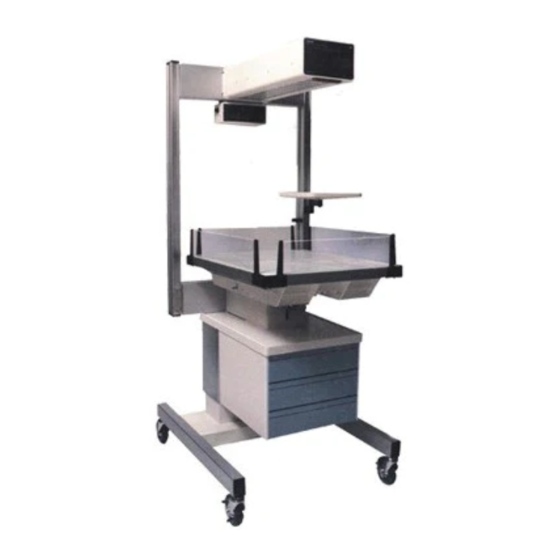
Model Descriptions Table of Contents 2001 IWS (international only) 3000 IWS 3050 IWS 3100 IWS 3150 IWS 3300 IWS 3400 IWS 3500 IWS 4000 IWS 4300 IWS 4400 IWS 6600-0255-000 12/20/00... - Page 8 Model Descriptions Table of Contents All models of the Ohmeda Medical Infant Warmer System provide a controlled source of radiant heat for infants and pediatric patients. The control system uses a microprocessor and provides both manual and servo modes of operation (except for the 2001 International, which is manual mode only).
-
Page 9: Definitions
Definitions Table of Contents Note: A Note provides additional information to clarify a point in the text. Important: An Important statement is similar to a note but used for greater emphasis. CAUTION: A Caution statement is used when the possibility of damage to the equipment exists. - Page 10 Notes Table of Contents viii viii 6600-0255-000 12/20/00...
-
Page 11: General Precautions
Table of Contents w w w w w Warnings Before using the Ohmeda Medical Infant Warmer System, read this entire manual. Attempting to use this device without a thorough understanding of its operation may result in patient or user injury. This device should only be... - Page 12 Notes Table of Contents 6600-0255-000 12/20/00...
-
Page 13: 1/Description
1.7 Accessories ......................1-3 1.1 General All models of the Ohmeda Medical Infant Warmer System provide a controlled source of radiant heat for infants and pediatric patients. The control system uses a microprocessor and provides both manual and servo modes of operation (model 2001 International is manual mode only). -
Page 14: Control Unit
1/Description The heater assembly consists of a radiant heater, parabolic reflector, observation light, and a visual alarm light. The parabolic reflector focuses radiant energy on the bed surface, minimizing energy loss due to scattering and providing an even field of radiant heat over the bed surface. -
Page 15: Accessories
1/Description 2. A mattress. 3. A tiltable, positive-lock bed platform which allows Trendelenburg and reverse Trendelenburg positioning at 4° and 8° tilt positions . 4. Three drawers which open from the front (or from the side in an optional configura- tion) for storing equipment or supplies. - Page 16 Notes 1/Description 6600-0255-000 12/20/00...
-
Page 17: Setup
For model 3050, 3100 and 3150 wall mounted units, refer to the mounting instructions in the Appendix. After removal from the shipping containers, inspect the Ohmeda Infant Warmer System and all accessory items for any signs of damage which may have occurred during shipment. File a damage claim with the shipping carrier if damage has occurred. -
Page 18: Heater Assembly Rotation
2/Setup and Checkout Procedures 3. For the model 3500, separate the warmer from the bassinet. 4. For units with casters, check that all casters are in firm contact with the floor and that the warmer is stable and moves freely. For the model 3500, check that all six casters on the warmer move freely. -
Page 19: Warmer/Bassinet Interlock (Model 3500 Only)
2/Setup and Checkout Procedures D. Warmer/Bassinet Interlock (model 3500 only) 1. Lock the 3500 warmer’s two rear casters. 2. Align the rear of the bassinet with the warmer’s base. 3. Push the bassinet into the alignment/locking track of the warmer’s base. 4. -
Page 20: Wall Mount Checkout
2/Setup and Checkout Procedures G. Wall Mount Checkout Figure 2-1 Wall mount pin insertion Verify that the warmer is rigidly secured to the wall and the heater assembly is level. Note: To access the control unit and display module for service procedures, either hinge pin may be removed, allowing the warmer to pivot away from the wall. -
Page 21: Control Unit Check
2/Setup and Checkout Procedures A. Control Unit Check 1. Connect the warmer power cord to an appropriate power source. Refer to the rating plate on the Warmer for the proper voltage needed. Switch the power On and verify the following on the Control Panel (Figure 2-1): a. -
Page 22: Elapsed Timer Check
2/Setup and Checkout Procedures Note: The functionality of the remainder of the alarms is continually checked by the microprocessor software during normal operation. If a fault occurs in any of this cir- cuitry, an indicator lights and a tone is sounded. The patient alarm can be verified manually by placing the unit in the manual mode and setting the power to 50%. -
Page 23: Interlock Switch Check
2/Setup and Checkout Procedures 3. Press the foot switches on both sides of the unit and verify that they raise and lower the bed. E. Interlock Switch Check 1. Place the warmer in the manual mode at 25% power output. 2. - Page 24 Notes 2/Setup and Checkout Procedures 6600-0255-000 12/20/00...
-
Page 25: 3/Operation
3/Operation 3/Operation In this section 3.1 Control Panel Operation ..................3-1 A. Displays ......................3-1 B. Indicator Lights ....................3-2 C. Switches ......................3-2 D. Alarms ......................3-4 3.2 Manual and Servo Mode Operation ..............3-7 3.3 Elapsed Timer Operation .................. 3-11 3.4 Bassinet Operation (model 3500 only) .............3-11 3.5 Bed Platform Operation ..................3-12 3.6 Side Panel Operation .................. -
Page 26: Indicator Lights
3/Operation % Power: The % power display indicates the percentage of maximum power that is being sup- plied to the radiant heater in 5% increments. The preheat range (0 to 25% power) allows operation without the 12 minute check patient alarm in the manual mode. Elapsed Time: The elapsed time display indicates elapsed time in minutes and seconds up to a maximum of 60 minutes. - Page 27 3/Operation • Alarm Silence • Start/Hold • Reset • Apgar Tones On/Off • Light On/Off • Raise bed (M) (Elevating Models Only) • Lower bed (?) (Elevating Models Only) Mode Switch: (all models except the 2001 international) This switch is used to select either the Manual or Servo mode of operation. An audio tone sounds momentarily when the mode switch is depressed.
-
Page 28: Alarms
3/Operation CAUTION: Do not continue to run the motor at the upper and lower limit positions; equip- ment damage may result. This switch raises the bed to a maximum height of 118 cm from the floor. Lower Bed (? ? ? ? ? ) (Elevating Models Only) This switch lowers the bed to a minimum height of 98 cm from the floor. - Page 29 3/Operation Probe Failure Alarm: (all models except the 2001 international) The probe failure alarm is only active in the servo mode of operation. The alarm activates when the skin temperature probe fails electrically due to an open or short circuit, or is disconnected from the Warmer. The heater deactivates and the patient temperature display flashes “HH.H”...
- Page 30 3/Operation Check Patient Alarm: 1. Manual Mode: The check patient alarm activates in the manual mode of operation when the heater has been energized at a power level greater than 25% for 12 minutes. The alternating single tone alarm is activated for this condition. Pressing the alarm silence switch silences this alarm and resets the timer for another 12 minutes of operation.
-
Page 31: Manual And Servo Mode Operation
3.2 Manual and Servo Mode Operation WARNING: Before using the Ohmeda Infant Warmer System, read this entire manual. Attempting to use this device without a thorough understanding of its operation may result in patient or user injury. This device should only be... - Page 32 3/Operation WARNING: Do not use the Warmer in the presence of flammable anesthetics; a possible explosion hazard exists under these conditions. Radiant energy can adversely affect blood components. When using intravenous tubing systems for delivery of blood components to patients occupying a warmer, shield any tubing with aluminum foil.
- Page 33 Rectal temperatures must never be used to servo control a patient’s temperature. The Ohmeda Patient probe lead is made from low mass wire that helps prevent probe detachment while reducing pulling on the neonate’s skin. Place the metal side of the skin temperature probe on the skin over the liver area of the infant’s abdomen.
- Page 34 3/Operation Connect the skin temperature probe to the Warmer by plugging the probe connector into the left side of the display module as viewed from the front. (See Figure 3-3.) CAUTION: Always remove the probe from the patient by grasping and removing the heat reflective patch first, then remove the probe from the patient or the patch.
-
Page 35: Elapsed Timer Operation
3/Operation The servo control temperature is adjusted by pressing the increase (M) or the decrease (?) touch switches. The control temperature can be adjusted from 35 to 37.5°C. In the servo mode, the temperature sensed by the skin temperature probe is used by the control system to modulate the radiant heat and maintain the patient’s skin temperature at the selected control temperature. -
Page 36: Bed Platform Operation
3/Operation To return the bassinet to its locked position, align the bassinet with the warmer . Push the bassinet over the warmer’s alignment/locking track. Continue pushing the bassinet until its locking pin drops into the socket at the end of the alignment/locking track. There should be an audible click when the pin drops into position. -
Page 37: Side Panel Operation
3/Operation 3.6 Side Panel Operation (See Figure 3-5.) WARNING: Do not leave the patient unattended when the side panels are lowered. Do not move the warmer by pushing or pulling on the bedside panels. This action may lead to the deterioration and breakage of the components which form a safety barrier around the infant. -
Page 38: X-Ray Procedures
3/Operation Tubes up to 9 mm O.D. Tubes up to Tubes up to Figure 3-6 13 mm O.D. 21 mm O.D. Tubing organizer panel WARNING: Inspect all patient connected tubes or wires before and after moving or tilting the bed. Tilting or moving the warmer bed up or down can pull on tubing or leads connected to the patient. - Page 39 3/Operation Carefully rotate the heater to the left. Figure 3-7 Heater Rotation for X-ray Procedures Using the tray WARNING: Limit the load placed on X-ray tray 2.3 Kg to avoid a tipping hazard. Never place an infant on the X-ray cassette tray. 1.
-
Page 40: Oxygen Administration
X-ray procedures. Incompatible materials in the path of the X-ray may adversely affect the quality of the X-ray image. Use of mattress or bedding materials other than those supplied by Ohmeda should be evaluated by a Neonatologist or Radiologist. - Page 41 (by hand only) to hold the cylinder firmly in place. Do not use wrenches or any other tool on the Tee Handle screws. 5. If only one oxygen cylinder is used, a yoke plug (Ohmeda Stock No. 6600-0399- 500) and a gasket are required to seal the unused yoke cylinder port.
-
Page 42: Mounting Accessories
3/Operation 3. Use new gaskets and full cylinders at each cylinder port (optionally, one full cylinder and a yoke plug may be used on a 2 cylinder oxygen manifold) 4. Open a cylinder valve at each manifold to charge the manifold(s) to a minimum of 5137 kPa and then close the valve(s). -
Page 43: Mounting And Releasing Procedure
3/Operation Rail system components mount to the uprights and provide ready access to commonly used equipment such as suction regulators, flowmeters, collection bottles, etc. Loosen mounting screw and Tighten mounting screw. place mounting block in position. Figure 3-10 Mounting rail system components A. -
Page 44: Ecmo Adapter
3/Operation Tighten the mounting screws. Figure 3-11 Mounting the Adapter Plate C. ECMO Adapter The ECMO adapter raises the bed an additional six inches to facilitate Extra-Corporeal Membrane Oxygeneration procedures on model 4400 and 5000 units. WARNING: Due to the increased height of units with the ECMO option installed, a tipping hazard may exist. -
Page 45: Using The Serial Data Interface
3/Operation The ThermaLink Serial data and Nurse Call connections are options offered with the Warmer (units with version 5.0 software or higher) . Your unit has this option if there is a nine pin connector on the back left side of the controller cover. See Figure 3-12. Using the Serial Data interface WARNING: Remote monitoring does not replace the need for direct patient observa-... -
Page 46: Nurse Call Checkout
3/Operation Refer to the Appendix for additional information on Nurse Call connections. Nurse Call checkout 1. Complete the checkout procedure in section 2.3. 2. Verify proper operation of the Nurse Call station. 3. Connect the Nurse Call connector to the warmer. 4. -
Page 47: 4/Cleaning And Disinfecting
4/Cleaning and Disinfecting 4/Cleaning and Disinfecting In this section 4.1 Cleaning ......................4-1 4.2 Wood Surfaces (model 3500 only) ..............4-2 4.3 Reusable Skin Temperature Probe ..............4-2 4.1 Cleaning WARNING: Disconnect power to the Warmer and allow the heat rod to cool before cleaning to avoid the possibility of a burn. -
Page 48: Wood Surfaces (Model 3500 Only)
4/Cleaning and Disinfecting 3. The mattress, X-ray tray, bed, and side panels may be cleaned without immersing by using a disinfecting agent safe for use on the materials. Note: Bleach (sodium hypochlorite) should not be used tthe soft heater end cap. The following lists recommended cleaning solutions that may be used safely. -
Page 49: 5/Maintenance
4. Ship to and bill to information. 5. Person (name and telephone number) to contact for functional questions. In all cases, other than where Ohmeda Medical’s warranty is applicable, repairs will be made at Ohmeda Medical’s current list price for replacement part(s) plus a reasonable labor charge. -
Page 50: Circuit Breaker Reset
A. Alarm Lamp Replacement (See Figure 5-2.) Lamp: GTE Sylvania 120 MB 6W, Ohmeda Medical Stock No. 0690-2100-315. 1. Disconnect the Warmer power cord and allow the unit to cool for 10 minutes. 6600-0255-000... -
Page 51: Observation Lamp Replacement
B. Observation Lamp Replacement (See Figures 5-8, 5-9 and 5-10.) Lamp: GE EXZ (Q50 MR16/NFL), Ohmeda Medical Stock No. 0208-0516-300 or GE EXN (Q50 MR16/FL). 1. Disconnect the power cord for the Warmer and allow the unit to cool for 10 minutes. - Page 52 5/Maintenance Carefully rotate the heater to the left. Figure 5-3 Heater rotation to the side position 3. Refer to Figure 5-4. Use a Phillips head screwdriver to remove the back panel of the heater assembly. Unscrew the two cover mounting screws and remove the cover.
-
Page 53: Yoke Manifold Assembly
5/Maintenance Lever Lamp Figure 5-5 Observation Lamp replacement 5.4 Yoke Manifold Assembly w w w w w WARNING: Never oil or grease oxygen equipment. Oils and grease oxidize readily, and in the presence of oxygen, will burn violently. Vac Kote is the oxygen service lubricant recommended (Stock No. -
Page 54: Maintenance Schedule
5/Maintenance 5.6 Maintenance Schedule The unit should be maintained in accordance with the procedures detailed in the Service Manual. Service maintenance must be performed by a technically competent individual as described in the Repair Policy. A. Operator Maintenance This schedule lists the minimum frequencies. Always follow hospital and local regula- tions for required frequencies. -
Page 55: 6/Illustrated Parts
6/Illustrated Parts 6/Illustrated Parts Figure 6-1 Illustrated parts Stock Number Description 0305-5060-300 Small mattress 46.2 x 64 cm 0305-5061-300 Large mattress 59 x 74.2 cm 0217-5221-300 Mattress Support Panel - all models except 3500 6600-0228-800 Corner Block Kit, black - all models except 3500 (4 Blocks) 6600-0230-800 Corner Block Kit, black - model 3500 (4 Blocks) 6600-0185-700... - Page 56 6/Illustrated Parts 0212-0300-600 Collection Bottle, 1/4 Gallon 0221-6267-300 Collection Bottle Bracket 0221-6285-300 Collection Bottle Cap with Float Assembly 6702-1224-905 DISS Continuous 3 Mode Suction Regulator with Overflow Trap 6600-0006-850 Drawer Kit, Stationary, beige, 3 drawer (Model 2001 & Series 3000) (Figure 6-11) 6600-0006-851 Drawer Kit, Stationary, beige, 3 drawer (Model 5000 &...
- Page 57 6/Illustrated Parts Figure 6-2 Adapter Plate (0217-5363-800) Figure 6-3 Air Flowmeter (50 psi) with DISS Fittings (0217- 5372-800) Figure 6-4 IV Pole, 30 cm (0217-5378-800) Figure 6-5 Airway Manometer Assembly (0217-5377-800) Figure 6-6 Oxygen Yoke and Regulator Assembly (see list on 6-1 and 6-2) Figure 6-7 Routing Clip (Package of 6)
- Page 58 6/Illustrated Parts Figure 6-8 Utility Post, 3.5 Inch stub (0217-5374-800) Figure 6-9 Vacuum Manifold with DISS Fittings (0217-5369-800) Figure 6-10 Vacuum Slide Bracket (0217-5367-800) Figure 6-11 Drawer Module Stationary (See list on 6-1 and 6-2) Figure 6-12 Instrument Shelf (See list on 6-1 and 6-2) Figure 6-13 Monitor Shelf (See list on 6-1 and 6-2)
-
Page 59: Appendix
Appendix Appendix In this section Temperature Conversion Chart .................. A-1 Servo Mode Algorithm ....................A-2 Infant Warmer System Specifications ................. A-2 Electrical ......................A-2 Controller ......................A-3 Alarms ........................ A-4 Environmental Specification ................A-5 Electromagnetic Compatibility (EMC) ..............A-6 Mechanical (Without Accessories) ..............A-6 3500 Bassinet .................... -
Page 60: Servo Mode Algorithm
Appendix Servo Mode Algorithm The servo mode uses the difference between the servo mode control temperature and the patient skin temperature to determine the percent of heater power required: Control Temp - Patient Temp Percent Heater Power 0.45°C 0.44 0.30°C 0.29 0.25°C 0.24... -
Page 61: Controller
2500 Vrms 60 Hz from the patient probe to the ac phase and neutral lines for one minute. WARNING: The patient probe is not isolated from earth ground. Any additional equip- ment used with the Ohmeda Infant Warmer System must comply with UL 544, CSA 22.2, IEC 601, and VDE 750. Leakage Current:... -
Page 62: Alarms
Appendix Temperature Sensing System: Range: 30 - 42°C Accuracy: ±0.3°C Resolution: ±0.1°C Probe interchangeability: ±0.1°C Probe Model Number: LA003 or LA005 Elapsed Timer: 60 minute elapsed timer with hold mode and Apgar tones. Manual Mode Heat Selector Range: All models: 0 to 540 watts in 20 increments of 5% each. -
Page 63: Environmental Specifications
Appendix System Failure Alarm: This alternating, two tone alarm cannot be silenced. Alarm activates and turns the heater off if any of the following occurs: 1. The analog-to-digital converter calibration drifts by more than 0.3°C. 2. The heater solid state relay fails. 3. -
Page 64: Electromagnetic Compatibility (Emc
Appendix Electromagnetic Compatibility (EMC) Specifications All models meet the requirements as specified in IEC 601-1-2 Collateral Standard Electromagnetic Compatibility - Requirements and Tests. Mechanical (Without Accessories) Overall Dimensions: Model Height - cm Depth - cm Width - cm Minimum Wt** number 2001 3000... - Page 65 Appendix Casters Model number 2001 13 cm dia., 2 locking, 2 non locking 3000 13 cm dia., 2 locking, 2 non locking 3050 — 3100 — 3150 — 3300 13 cm dia., 2 locking, 2 non locking 3400 13 cm dia., 2 locking, 2 non locking 3500 Warmer- 5 cm dia., 2 locking, 4 non locking Bassinet- 13 cm dia., 2 locking, 2 non locking...
-
Page 66: 3500 Bassinet
Appendix 3500 Bassinet Material: Select oak and oak veneer. Optional custom stain colors are available. Storage: Three Drawer storage opening from either side or the front of the unit, depending on the model ordered. Accessories Accessories include the following (see also Section 6/Illustrated Parts ): Air/Oxygen Yoke and Regulator: Pin indexed oxygen yokes accommodate two U.S. - Page 67 Appendix Instrument shelf: Dimensions 30 x 30 cm Load limit: 9kg Oxygen flowmeter with DISS fittings: 0 to 15 LPM Air flowmeter with DISS fittings: 0 to 15 LPM Airway Manometer: -20 to +100 centimeters of water IV pole - 30 and 60 cm Gas manifold with 1/8 inch NPT fitting 9 cm utility post Drawer Storage Accessory:...
-
Page 68: Radiant Energy Distribution
The warmer may be connected to a Hewlett Packard CMS Monitor via a Vuelink open interface module (HP P/N M1032A Option A05) and HP Ohmeda option cable. The parameters passed to the HP monitor are: patient temperature, set temperature, and heater power level;... - Page 69 Appendix Note: In the event of power failure, all serial communication will cease until power is restored. The Nurse Call and the serial data output share the same female, nine pin, d-type connector (DB9F). Pin 2: Receive Data (warmer input) Pin 3: Transmit Data (warmer output) Pin 5: Gnd (Signal Ground) Cable requirements...
-
Page 70: Nurse Call Specifications
Appendix alrmleds This series of bits represents the alarm LEDs. If an LED is illuminated, the correspond- ing bit is set to 1 (alarm active). If there is no alarm, the bit is set to 0. Checking the bits from right to left is the same as checking the alarm LEDs from top to bottom: 00000100 Probe Failure Alarm Patient Temperature Alarm... -
Page 71: Installing Wall Mounted Units
Appendix Table A-1 Nurse Call signals Warmer Nurse Call Signal Status Pins 1&6 Pins 1&9 Normal Closed Open Alarm Open Closed Power switch off Open Closed or power fails Nurse Call cable Open Open disconnected WARNING: If you use the normally open Nurse call connection, a disconnected Nurse Call cable DOES NOT trigger a remote alarm. -
Page 72: Pre-Installation Preparation
Appendix The following instructions describe the manufacturer’s recommended method of installation in new construction. Use only the Ohmeda hardware provided to mount the model 3050, 3100, and 3150. The installation should be approved by the appropriate State and Local authorities. - Page 73 Appendix 3. Utilizing a level, position the hinge bracket on the wall. The bottom edge of the heater mounting bracket on the model 3050 and 3100 must be 69 - 5, + 23 cm, inches from the bed surface of the mattress that will be used. See Figure A-3. The model 3150 integral bed warmer already comes with 69±5 cm bed-to-heater spacing.
- Page 74 Appendix Straps Metal Channel Ring Drywall Track Figure A-4 Toggler® anchor installation 7. Mount the hinge bracket on the wall with the flat washers, split ring washers and screws provided. See Figure A-5. Tighten the screws with approximately 80 lb/in of torque. Note: The screws provided (3/8 - 16 UNC, 2 a”...
- Page 75 Appendix Drywall 19 mm Dia. Hole 44 cm Flat Washer Slit Ring Washer Mounting Screw Stud Track ® Toggler Hinge Pin Hinge Bracket Power Cord Heater Assembly Figure A-5 Mounting the warmer 10. Position the lower mounting bracket on the wall. Use the lower hinge bracket as a template to mark the mounting holes on the wall for the lower bracket.
- Page 76 Notes Appendix A-18 A-18 6600-0255-000 12/20/00...
- Page 77 Notes Appendix A-19 A-19 6600-0255-000 12/20/00...
- Page 78 Notes Appendix A-20 A-20 6600-0255-000 12/20/00...
- Page 79 Warranty Appendix This Product is sold by Ohmeda Medical under the warranties set forth in the following paragraphs. Such warranties are extended only with respect to the purchase of this Product directly from Ohmeda Medical or Ohmeda Medical’s Authorized Dealers as new merchandise and are extended to the first Buyer thereof, other than for purpose of resale.
- Page 80 Fax 410-888-0544 North America Asia/Pacific Europe Latin America, Caribbean United States Japan France Datex-Ohmeda Latin America Datex-Ohmeda K. K. Datex-Ohmeda S.A.S. 10685 North Kendall Drive TRC Annex 9F 17 rue Jean-Elysée Dupuy Customer Service and Miami, FL 33176 6-1-1 Heiwajima...