Advertisement
OWNER'S
MANUAL
MODEL NO.
390.251183
390.251983
390.252283
CAUTION:
Read and Follow
All Safety Rules and
Operating Instructions
Before First Use of
This Product.
Save This Manual For
Future Reference.
Sears, Roebuck and Co., Hoffman Estates, IL 60179 U.S.A.
PRINTED IN U.S.A.
CRAFTSMAN
MODEL NO.
390.251183
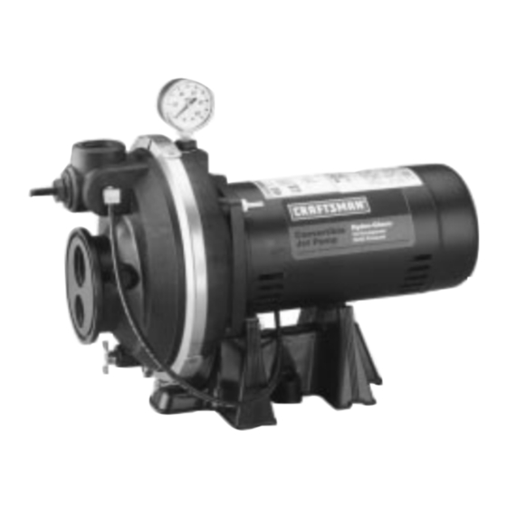
"HYDROGLASS"
CONVERTIBLE DEEP
WELL JET PUMP
• Safety Instructions
• Installation
• Operation
• Troubleshooting
• Repair Parts
CRAFTSMAN
PROFESSIONAL
MODEL NOS.
390.251983
390.252283
®
®
F642-9905
Form No.
(Rev. 4/19/01)
Advertisement

Related Manuals for Craftsman HYDROGLASS 390.251183


Summary of Contents for Craftsman HYDROGLASS 390.251183
- Page 1 OWNER’S CRAFTSMAN MODEL NO. MANUAL 390.251183 MODEL NO. 390.251183 390.251983 390.252283 CRAFTSMAN PROFESSIONAL MODEL NOS. 390.251983 390.252283 ® ® “HYDROGLASS” CAUTION: Read and Follow CONVERTIBLE DEEP All Safety Rules and WELL JET PUMP Operating Instructions Before First Use of • Safety Instructions This Product.
- Page 2 READ AND FOLLOW SAFETY INSTRUCTIONS! This is the safety alert symbol. When you see this symbol on your pump or in this manual, look for one of the fol- lowing signal words and be alert to the potential for per- sonal injury: DANGER warns about hazards that will cause serious per- sonal injury, death or major property damage if ignored.
-
Page 3: Table Of Contents
Maintenance ..............10 Service ................11-12 Pump Performance............14 Repair Parts..............15-19 FULL ONE YEAR WARRANTY ON CRAFTSMAN ® WELL PUMPS For one year from the date of purchase, Sears will repair or replace this pump, free of charge, if defective in material or workmanship. - Page 4 INSTALLATION – DEEP WELL PLASTIC PIPE 1" PLASTIC PIPE 1-1/4" WELL SEAL PIPE ADAPTERS 1" PLASTIC PIPE 1-1/4" PLASTIC PIPE CHECK VALVE AND STRAINER 1400 1194 Figure 1 – Captive Air ® Pressure Tank Installation - Deep Well PLASTIC PIPE 1"...
- Page 5 INSTALLATION – SHALLOW WELL Figure 3 – Captive Air ® Pressure Tank Installation - Shallow Well Figure 4 – Standard Pressure Tank Installation - Shallow Well...
-
Page 6: Installation
INSTALLATION NOTICE: Use Teflon tape supplied with the pump or Plasto- In a shallow well installation, the jet assembly is attached Joint Stik1 for making all pipe-thread connections to the directly to the pump because the vacuum created will pull pump itself. - Page 7 INSTALLATION STEEL PIPING INSTALLATIONS SHALLOW WELL INSTALLATION AND OPERATION When steel pipe is used to install the jet, be sure all pipes are clean and the ends are reamed. Screw both 1-1/4” NPT Installing the Pump on a Shallow Well suction pipe and 1’’...
- Page 8 INSTALLATION Discharge Pipe Sizes NEVER run pump dry. Running pump with- When the pump is set a distance from the house, barns, or out water may overheat unit, damaging seals and possibly other points of water use, the discharge pipe size should be burning persons handling pump.
-
Page 9: Electrical
ELECTRICAL Disconnect power before working on pump, motor, pressure switch, or wiring. Your Motor Terminal Board (under the motor end cover) if line voltage is 230 Volts or if you have a single voltage and Pressure Switch look like one of those shown below. motor. -
Page 10: Operation
OPERATION MAINTENANCE PRIMING THE SHALLOW WELL PUMP LUBRICATION TO PREVENT DAMAGE TO INTERNAL PARTS, DO NOT It is not necessary to lubricate the pump or its motor. The START MOTOR UNTIL PUMP HAS BEEN FILLED WITH motor has two ball bearings lubricated for life. The me- WATER. -
Page 11: Service
SERVICE REMOVING MOTOR FOR SERVICE 8. Slide seal assembly on shaft (sealing face first) until rub- ber drive ring hits shaft shoulder. BE SURE you don’t chip AND REPLACING SHAFT SEAL or scratch sealing face on shaft shoulder. Should repair or replacement of motor or seal be necessary, 9. - Page 12 SERVICE CLEANING IMPELLER HOW TO HANDLE A GASEOUS WELL 1. Disassemble pump per disassembly instruction on Page In some localities well water contains gases which must be allowed to escape before the water is used. This can be done as shown in Figure 12. 2.
- Page 13 TROUBLESHOOTING CHART SYMPTOM POSSIBLE CAUSE(S) CORRECTIVE ACTION Motor will not run 1. Disconnect switch is off 1. Be sure switch is on 2. Fuse is blown 2. Replace fuse 3. Starting switch is defective 3. Replace starting switch 4. Wires at motor are loose, 4.
-
Page 14: Pump Performance
TROUBLESHOOTING CHART SYMPTOM POSSIBLE CAUSE(S) CORRECTIVE ACTION Leaks at the metal 1. Loose clamps or O-Ring 1. First check the clamp tightening screw to see if it is tight. If it is tight and clamps not sealed slight leakage still occurs, place a piece of wood on the clamp and firmly tap the wood with a hammer. - Page 15 SHALLOW WELL JET AND CHECK VALVE ASSEMBLY STOCK NO. 29650 For Pump Models 390.251183, 390.251983 and 390.252283 To Order Parts, Call Sears Product Service, 1-800-366-7278 1722 0495 Figure 13 Repair Parts Part Number Part Description U9-202 O-Ring - Jet Body J19-6 Clamp U9-201...
- Page 16 REPAIR PARTS 1402 1194 Figure 14...
- Page 17 1/2 HP 3/4 HP 1 HP Model Model Model Part 390.251183 390.251983 390.252283 Description J218-953C – – Motor - 1/2 HP, 115/230V, 60 Cycle – J218-954C – Motor - 3/4 HP, 115/230V, 60 Cycle – – J218-955C Motor - 1 HP, 115/230V, 60 Cycle 17351-0009 17351-0009 17351-0009...
-
Page 18: Repair Parts
REPAIR PARTS Single Pipe Jets Double Pipe Jets SINGLE PIPE JETS Part Description Pkg. Max. Stamped Pump Stock Pumping Packer Check Valve Turned Casing Size Model Depth Venturi Nozzle* Nozzle Body Leather Spacer Washer Valve Seat Coupling Adapter 40’ J32P-24 J34P-44 J40-24 J57-1 J43-14P... - Page 19 REPAIR PARTS VERTICAL CASING ADAPTERS To Order Parts, Call Sears Product Service, 1-800-366-7278 1723 0495 2” AND 3” VERTICAL CASING ADAPTER 2” Vertical 3” Vertical Casing Casing Part Adapter Adapter Description – J216-13 – 2” Vertical Casing Adapter – – J216-14 3”...
- Page 20 ® OWNER’S ® “HYDROGLASS” MANUAL CONVERTIBLE DEEP WELL JET PUMP For the repair or replacement parts you need MODEL NO. Call 7 am - 7 pm, 7 days a week 1-800-366-PART 390.251183 (1-800-366-7278) 390.251983 390.252283 For in-home major brand repair service Call 24 hours a day, 7 days a week 1-800-4-REPAIR REPAIR SERVICES...