D-Link DFL-1100 User Manual
Network security firewall
Hide thumbs
Also See for DFL-1100:
- Manual (91 pages) ,
- User manual (86 pages) ,
- Installation manual (25 pages)

Related Manuals for D-Link DFL-1100


Summary of Contents for D-Link DFL-1100
- Page 1 D-Link DFL-1100 Network Security Firewall Manual Building Networks for People (04/19/2005)
-
Page 2: Table Of Contents
Introduction to Local Area Networking ... 8 LEDs & Physical Connections... 9 Package Contents ... 10 System Requirements ... 10 Managing D-Link DFL-1100 ... 11 Resetting the DFL-1100 ...11 Administration Settings... 12 Administrative Access ... 12 Add ping access to an interface...13 Add Admin access to an interface...13... - Page 3 Add Administrative User...42 Change Administrative User Access level ...43 Change Administrative User Password...43 Delete Administrative User...44 Users... 45 The DFL-1100 RADIUS Support...45 Enable User Authentication via HTTP / HTTPS...46 Enable RADIUS Support...46 Add User ...47 Change User Password ...47 Delete User ...48 Schedules ...
- Page 4 Grouping Services ...52 Protocol-independent settings ...53 VPN... 54 Introduction to IPSec...54 Introduction to PPTP...54 Introduction to L2TP...55 Point-to-Point Protocol ...55 Authentication Protocols ...56 MPPE, Microsoft Point-To-Point Encryption...56 L2TP/PPTP Clients ...57 L2TP/PPTP Servers...58 IPSec VPN between two networks ...59 Creating a LAN-to-LAN IPSec VPN Tunnel ...59 VPN between client and an internal network ...60 Creating a Roaming Users IPSec Tunnel ...60 Adding an L2TP/PPTP VPN Client ...61...
- Page 5 Ping ... 71 Ping Example ...71 Dynamic DNS... 72 Add Dynamic DNS Settings ...72 Backup ... 73 Exporting the DFL-1100’s Configuration ...73 Restoring the DFL-1100’s Configuration...73 Restart/Reset ... 74 Restoring system settings to factory defaults ...75 Upgrade ... 76 Upgrade Firmware ...76 Upgrade IDS Signature-database...76...
- Page 6 Settings for Main office ...113 Windows XP client and L2TP server ...116 Settings for the Windows XP client ...116 Settings for Main office ...118 Intrusion Detection and Prevention ... 120 Appendixes... 123 Appendix A: ICMP Types and Codes ... 123 Appendix B: Common IP Protocol Numbers ...
-
Page 7: Introduction
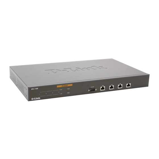
The DFL-1100 provides four 10/100Mbps Ethernet network interface ports, which are (1) Internal/LAN, (1) External/WAN, (1) DMZ, and (1) ETH4 port. In addition the DFL-1100 also provides a user-friendly Web UI that allows users to set system parameters or monitor network activities using a Web browser supporting Java. -
Page 8: Introduction To Local Area Networking
Introduction to Local Area Networking Local Area Networking (LAN) is the term used when connecting several computers together over a small area such as a building or group of buildings. LANs can be connected over large areas. A collection of LANs connected over a large area is called a Wide Area Network (WAN). -
Page 9: Leds & Physical Connections
DC Power (on rear of unit): Use the included PC power cable to connect to an 110/120VAC electrical receptacle. Do not use more than 110/120VAC to power the device, doing so will damage the unit. Power Switch (on rear of unit): Use the Power switch to turn the DFL-1100 off and on. -
Page 10: Package Contents
Package Contents Contents of Package: • D-Link DFL-1100 Firewall • Manual and CD • Installation Guide • PC Power cable • Straight-through CAT-5 cable • RS-232 Null Modem Cable If any of the above items are missing, please contact your reseller. -
Page 11: Managing D-Link Dfl-1100
Configuration Changes page, by choosing the time from the dropdown menu. Resetting the DFL-1100 To reset the DFL-1100 to factory default settings you must do so through the Web UI or the Console Interface. Refer to the section on resetting the DFL-1100 to factory default settings for more information. -
Page 12: Administration Settings
Ping – If enabled, it specifies who can ping the IP interface of the DFL-1100. Enabling Default allows anyone to ping the interface IP. Admin – If enabled, it allows all users with admin access to connect to the DFL-1100 and change configuration; this can be HTTPS or HTTP and HTTPS. -
Page 13: Add Ping Access To An Interface
192.168.1.0/24 for a whole class C network or 172.16.0.1 – 172.16.0.10 for a range of IP addresses. Step 4. Specify protocol to be used to access the DFL-1100 via the dropdown menu. Select HTTP and HTTPS (Secure HTTP) or HTTPS only. -
Page 14: Add Read-Only Access To An Interface
192.168.1.0/24 for a whole class C network or 172.16.0.1 – 172.16.0.10 for a range of IP addresses. Step 4. Specify protocol to be used to access the DFL-1100 via the dropdown menu. Select HTTP and HTTPS (Secure HTTP) or HTTPS only. -
Page 15: System
Please keep in mind that the DHCP scope will also need to be changed to correspond with the new LAN, DMZ, or ETH4 IP. If the computer through which the DFL-1100 is being configured is a DHCP client, you will need to manually release and renew the IP address after applying changes and restarting. -
Page 16: Wan Interface Settings - Using Static Ip
WAN Interface Settings – Using Static IP If you are using Static IP, you have to fill in the IP address information provided to you by your ISP. All fields are required except the Secondary DNS Server. Note: Do not use the numbers displayed in these fields, they are only used as an example. -
Page 17: Wan Interface Settings - Using Pppoe
WAN Interface Settings – Using PPPoE Use the following procedure to configure DFL-1100 interface to use PPPoE (Point-to-Point Protocol over Ethernet). configuration is required if your ISP uses PPPoE to assign the IP address of the external interface. You will have to fill in the username and password provided to you by your ISP. -
Page 18: Wan Interface Settings - Using Pptp
• PPTP Server IP – The IP of the PPTP server that the DFL-1100 will connect to. Before PPTP can be used to connect to your ISP, the physical (WAN) interface parameters must be input. You can use either DHCP or Static IP, depending on the type of ISP used. -
Page 19: Wan Interface Settings - Using L2Tp
• L2TP Server IP – The IP of the L2TP server that the DFL-1100 will connect to. Before L2TP can be used to connect to your ISP, the physical (WAN) interface parameters must be input. You can use either DHCP or Static IP, depending on the type of ISP used. -
Page 20: Wan Interface Settings - Using Bigpond
DFL-1100. For example, the policy for the web server might be given higher priority than the policies for most employees' computers. -
Page 21: Mtu Configuration
Ideally, you want this MTU to be the same as the smallest MTU of all the networks between the DFL-1100 and the Internet. If the packets the DFL-1100 sends are larger, they get broken up or fragmented, which could slow down transmission speeds. -
Page 22: Vlan
VLAN Click on System in the menu bar, and then click VLAN below it, this will give a list of all configured VLAN Tags, which should look something like this: Add a new VLAN Follow these steps to add a new route. Step 1. -
Page 23: Routing
Click on System in the menu bar, and then click Routing below it; this will provide a list of all configured routes, and it will look something like this: The Routes configuration section describes the firewall’s routing table. The DFL-1100 uses a slightly different method of describing routes compared to most other systems. -
Page 24: Add A New Static Route
Add a new Static Route Follow these steps to add a new route. Step 1. Go to System and Routing. Step 2. Click on Add new in the bottom of the routing table. Step 3. Choose the interface that the route should be sent through from the dropdown menu. -
Page 25: High Availability
As is the case with all other firewalls supporting stateful failover, the D-Link High Availability will only work between two D-Link DFL-1100 Firewalls. As the internal workings of different firewalls, and, indeed, different major versions of the same firewall, can be radically different, there is no way of communicating "state"... -
Page 26: Ip Addresses Explained
IP Addresses explained For each cluster interface, there are three IP addresses: • Two "real" IP addresses; one for each firewall. These addresses are used to communicate with the firewalls themselves, i.e. for remote control and monitoring. They should not be associated in any way with traffic flowing through the cluster; if either firewall is inoperative, the associated IP address will simply be unreachable. -
Page 27: Cluster Heartbeats
Cluster heartbeats A firewall detects that its peer is no longer operational when it can no longer hear "cluster heartbeats" from its peer. Currently, a firewall will send five cluster heartbeats per second. When a firewall has "missed" three heartbeats, i.e. after 0.6 seconds, it will be declared inoperative. -
Page 28: Setting Up A High Availability Cluster
Setting up a High Availability cluster First of all, each of the DFL-1100 Firewalls must be setup so far that one can manage them over the web interface. In this example the two units are configured as follow, the master DFL-1100 will be configured with 192.168.1.2 on its internal interface, and the slave DFL-1100 with 192.168.1.3. -
Page 29: Interface Monitoring
Now login to the slave firewall and click on System in the menu bar, and then click HA below it; in this screen you will click on Receive configuration from first unit. You will need to fill in the cluster id configured on the first unit. When you click Apply the unit should transfer the configuration from the first unit and you HA cluster should be operating. -
Page 30: Logging
The D-Link DFL-1100 provides several options for logging activity. The D- Link DFL-1100 logs activity by sending the log data to one or two log receivers in the network. All logging is done to SYSLog recipients. The log format used for SYSLog logging is... -
Page 31: Enable Logging
Step 2. Choose the sensitivity level. Step 3. In the SMTP Server field, fill in the SMTP server to which the DFL-1100 will send the e-mail alerts. Step 4. Specify up to three valid email addresses to receive the e-mail alerts. -
Page 32: Time
Time Click on System in the menu bar, and then click Time below it. This will give you the option to either set the system time by synchronizing with an Internet Network Time Server (NTP) or by entering the system time manually. -
Page 33: Changing Time Zone
Changing time zone Follow these steps to change the time zone. Step 1. Choose the correct time zone in the drop down menu. Step 2. Specify the dates to begin and end daylight saving time or choose no daylight saving time by checking the correct box. Click the Apply button below to apply the settings or click Cancel to discard changes. -
Page 34: Firewall
The first step in configuring security policies is to configure the mode for the firewall. The firewall can run in NAT or No NAT (Route) mode. Select NAT mode to use DFL-1100 network address translation to protect private networks from public networks. In NAT mode, you can connect a private network to the internal interface, a DMZ network to the DMZ interface, and a public network, such as the Internet, to the external interface. -
Page 35: Source And Destination Filter
Source and Destination Filter Source Nets – Specifies the sender span of IP addresses to be compared to the received packet. Leave this blank to match everything. Source Users/Groups – Specifies if an authenticated username is needed for this policy to match. -
Page 36: Intrusion Detection / Prevention
Inspection Only or Prevention. Inspection Only will only inspect the traffic, and if the DFL-1100 detects anything it will log, e-mail an alert (if configured), and pass on the traffic. If Prevention is used the traffic will be dropped and logged and if configured, an e-mail alert will be sent. -
Page 37: Add A New Policy
There are two ways to configure Policy Routing; both include specifying the Gateway to send the traffic over. The first one, Redirect via routing (make gateway next hop), will just reroute the traffic to the given gateway as if it was just another router. The second mode, Via address translation (change destination IP), will change the destination IP in the IP header and then pass the packet on to the gateway, used for example in transparent squid-proxy setups. -
Page 38: Change Order Of Policy
Change order of policy Follow these steps to change the order of a policy. Step 1. Choose the policy list for which you would like to change the order from the available policy lists. Step 2. Click on the Edit link corresponding to the rule you want to move. Step 3. -
Page 39: Configure Intrusion Prevention
Configure Intrusion Prevention Follow these steps to configure IDP on a policy. Step 1. Choose the policy you would like have IDP on. Step 2. Click on the Edit link corresponding to the rule you want to configure. Step 3. Enable the Intrusion Detection / Prevention checkbox. Step 4. -
Page 40: Add A New Mapping
Port mapping / Virtual Servers The Port mapping / Virtual Servers configuration section is where you can configure virtual servers (such as a LAN Web server) on the LAN or DMZ Interfaces to be accessible through the WAN. One may also regulate how bandwidth management (traffic shaping) is applied to traffic flowing through the WAN interface of the firewall to the LAN or DMZ. -
Page 41: Delete Mapping
Delete mapping Follow these steps to delete a mapping. Step 1. Choose the mapping list (WAN, LAN, or DMZ) you would like do delete the mapping from. Step 2. Click on the Edit link corresponding to the rule you want to delete. Step 3. -
Page 42: Administrative Users
The first column shows the access levels, Administrator and Read-only. An Administrator user can add, edit and remove rules, change settings of the DFL-1100 and so on. The Read- only user can only look at the configuration. The second column shows the users in each access level. -
Page 43: Change Administrative User Access Level
Change Administrative User Access level To change the access lever of a user click on the user name and you will see the following screen. From here you can change the access level by entering the appropriate level in the Group Membership field. Access levels •... -
Page 44: Delete Administrative User
Delete Administrative User To delete a user click on the user name and you will see the following screen. Follow these steps to delete an Administrative User. Step 1. Click on the user you would like to delete. Step 2. Enable the Delete user checkbox. -
Page 45: Users
Before any traffic is allowed to pass through any policies configured with username or groups, the user must first authenticate him/her-self. The DFL-1100 can either verify the user against a local database or pass along the user information to an external authentication server, which verifies the user and the given password, and transmits the result back to the firewall. -
Page 46: Enable User Authentication Via Http / Https
Enable User Authentication via HTTP / HTTPS Follow these steps to enable User Authentication. Step 1. Enable the checkbox for User Authentication. Step 2. Specify if HTTP and HTTPS or only HTTPS should be used for the login. Step 3. Specify the idle-timeout, the time a user can be idle before being logged out by the firewall. -
Page 47: Add User
Add User Follow these steps to add a new user. Step 1. Click on add corresponding to the type of user you would like to add, Admin or Read-only. Step 2. Fill in User name; make sure you are not trying to add one that already exists. -
Page 48: Delete User
Delete User To delete a user click on the user name and you will see the following screen. Follow these steps to delete a user. Step 1. Click on the user you would like to delete. Step 2. Enable the Delete user checkbox. -
Page 49: Schedules
The DFL-1100 can be configured to have a start time and stop time, as well as 2 different time periods in a day. For example, an organization may... -
Page 50: Add New One-Time Schedule
Add new one-time schedule Follow these steps to create and add a new one-time schedule. Step 1. Go to Firewall and Schedules and choose Add new. Step 2. Choose the starting and ending date and hour when the schedule should be active. Step 3. -
Page 51: Services
Services A service is basically a definition of a specific IP protocol with corresponding parameters. The service http, for instance, is defined as using the TCP protocol with destination port 80. Services are simplistic, in that they cannot carry out any action in the firewall on their own. Thus, a service definition does not include any information whether the service should be allowed through the firewall or not. -
Page 52: Adding Ip Protocol
Adding IP Protocol When the type of the service is IP Protocol, an IP protocol number may be specified in the text field. To have the service match the GRE protocol, for example, the IP protocol should be specified as 47. A list of some defined IP protocols can be found in the appendix named “IP Protocol Numbers.”... -
Page 53: Protocol-Independent Settings
It is generally not a good idea to allow any inbound ICMP message to be able to have those error messages forwarded. To solve this problem, the DFL-1100 can be instructed to pass an ICMP error message only if it is related to an existing connection. Check this option to enable this feature for connections using this service. -
Page 54: Vpn
IPSec, Internet Protocol Security, is a set of protocols defined by the IETF, Internet Engineering Task Force, to provide IP security at the network layer. An IPSec based VPN, such as that of the DFL-1100, is made up of two basic parts: •... -
Page 55: Introduction To L2Tp
Link Control Protocols (LCP) to negotiate parameters, test and establish the link. • Network Control Protocol (NCP) to establish and negotiate different network layer protocols (DFL-1100 only supports IP) • Data encapsulation to encapsulate datagram’s over the link. To establish a PPP tunnel, both sides send LCP frames to negotiate parameters and test the data link. -
Page 56: Authentication Protocols
RFC 1994. CHAP uses an MD5 one-way encryption scheme to hash the response to a challenge issued by the DFL-1100. CHAP is superior to PAP in that the password is never sent over the link. Instead the password is used to create the one-way MD5 hash. -
Page 57: L2Tp/Pptp Clients
L2TP/PPTP Clients Settings for L2TP/PPTP Client Configuration Name – Specifies a friendly name for the PPTP/L2TP Client tunnel. Username – Specify username for this PPTP/L2TP Client tunnel. Password/Confirm Password – The password to use for this PPTP/L2TP Client tunnel. Interface IP - Specifies if the L2TP/PPTP Client tunnel should use a Static IP or obtain a dynamic IP from the server. -
Page 58: L2Tp/Pptp Servers
L2TP/PPTP Servers Settings L2TP/PPTP Server Configuration Name – Specifies a name for this PPTP/L2TP Server. Outer IP - Specifies the IP that the PPTP/L2TP server should listen on, leave it Blank for the WAN IP. Inner IP - Specifies the internal IP of the VPN tunnel. -
Page 59: Ipsec Vpn Between Two Networks
PSK, make sure both firewalls use exactly the same PSK. Step 5. For Tunnel Type, choose LAN-to-LAN tunnel and specify the network behind the other DFL-1100 as Remote Net. Also specify the external IP of the other DFL-1100, either an IP or a DNS name. -
Page 60: Vpn Between Client And An Internal Network
Internet. Communication between the client and the internal network takes place in an encrypted VPN tunnel that connects the DFL-1100 and the roaming users across the Internet. The example shows a VPN between a roaming VPN client and the internal network, but you can also create a VPN tunnel that uses the DMZ network. -
Page 61: Adding An L2Tp/Pptp Vpn Client
Adding an L2TP/PPTP VPN Client Follow these steps to add an L2TP or PPTP VPN Client configuration. Step 1. Go to Firewall and VPN and choose Add new PPTP client or Add new L2TP client in the L2TP/PPTP Clients section. Step 2. -
Page 62: Vpn - Advanced Settings
VPN – Advanced Settings Advanced settings for a VPN tunnel is used when the user needs to change some characteristics of the tunnel to, for example, try to connect to a third party VPN Gateway. The different settings per tunnel are: Limit MTU With this setting it is possible to limit the MTU (Max Transferable Unit) of the VPN tunnel. -
Page 63: Proposal Lists
Proposal Lists To agree on the VPN connection parameters, a negotiation process is performed. As the result of the negotiations, the IKE and IPSec security associations (SA) are established. As the name implies, a proposal is the starting point for the negotiation. A proposal defines encryption parameters, for instance encryption algorithm, life times etc, that the VPN gateway supports. -
Page 64: Certificates
Web interface to provide HTTPS access. Note: The certificate named Admin can only be replaced by another certificate. It cannot be deleted or renamed. This is used for HTTPS access to the DFL-1100. Certificates of remote peers This is a list of all certificates of individual remote peers. -
Page 65: Identities
Note: If the uploaded certificate is a CA certificate, it will automatically be placed in the Certificate Authorities list, even if Add New was clicked in the Remote Peers list. Similarly, a non-CA certificate will be placed in the Remote Peers list even if Add New was clicked from the Certificate Authorities list. -
Page 66: Content Filtering
Content Filtering DFL-1100 HTTP content filtering may be configured to scan all HTTP protocol streams for URLs or for potentially dangerous Web page content. If a match is found between the requested URL and the URL Blacklist the DFL-1100 will block the Web page. -
Page 67: Edit The Url Global Blacklist
Edit the URL Global Blacklist Follow these steps to add or remove a URL. Step 1. Navigate to Firewall Content Filtering and choose Edit global Blacklist. Step 2. Add or edit a URL that should be filtered and blocked. File extensions may also be defined to block download of specified file types. -
Page 68: Servers
DHCP requests and forward those requests to a specified DHCP server. The relay function allows the use of existing DHCP servers in conjunction with the DFL-1100 to ensure all users on all interfaces receive IP addresses when requested. The DFL-1100 will also configure dynamic routes based on those DHCP leases. -
Page 69: Enable Dhcp Server
Enable DHCP Server To enable the DHCP Server on an interface, click on Servers in the menu bar, and then click DHCP Server below it. Follow these steps to enable the DHCP Server on the LAN interface. Step 1. Choose the LAN interface from the Available interfaces list. Step 2. -
Page 70: Dns Relay Settings
DNS Relay Settings Click on Servers in the menu bar, and then click DNS Relay below it. The DFL-1100 contains a DNS Relay function that can be configured to relay DNS queries from the internal LAN to the DNS servers used by the firewall itself. -
Page 71: Tools
Tools Ping Click on Tools in the menu bar, and then click Ping below it. This tool is used to send a specified number of ICMP Echo Request packets to a given destination. All packets are sent in immediate succession rather than one per second. This method is the best suited for diagnosing connectivity problems. -
Page 72: Dynamic Dns
Dynamic DNS The Dynamic DNS (requires Dynamic DNS Service) allows you to alias a dynamic IP address to a static hostname, allowing your device to be more easily accessed by a specific name. When this function is enabled, the IP address in Dynamic DNS Server will be automatically updated with the new IP address provided by ISP. -
Page 73: Backup
System Administrators can restore the firewall’s configuration file with the one stored on disc. Exporting the DFL-1100’s Configuration Follow these steps to export the configuration. Step 1. Under the Tools menu and the Backup section, click on the Download configuration button. -
Page 74: Restart/Reset
Restart/Reset Restarting the DFL-1100 Follow these steps to restart the DFL-1100. Step 1. Choose if you want to do a quick or full restart. Step 2. Click Restart Unit and the unit will restart. -
Page 75: Restoring System Settings To Factory Defaults
Wizard to complete basic connectivity configurations. You can restore your system settings by uploading a previously generated system configuration file to the DFL-1100 if a backup of the device has been downloaded to your Local Machine Prior to reset. -
Page 76: Upgrade
Upgrade The DFL-1100’s software, IDS signatures, and system parameters are all stored on a flash memory card. The flash memory card is re-writable and re-readable. Upgrade Firmware upgrade firmware of the DFL-1100, obtain the latest version from support.dlink.com (US). Make... -
Page 77: Status
Status In this section, the DFL-1100 displays the status information about the Firewall. Administrator may use the Status section to check the System Status, Interface statistics, VPN status, IP connections, and DHCP Servers Status. System Click on Status in the menu bar, and then click System below it. A window will appear providing some information about the DFL-1100. -
Page 78: Interfaces
Click on Status in the menu bar, and then click Interfaces below it. A window will appear providing information about the interfaces on the DFL-1100. By default, information about the LAN interface will be displayed. To see information for a specific interface, click on the respective link. -
Page 79: Vpn
Click on Status in the menu bar, and then click Interfaces below it. A window will appear providing information about the VPN connections on the DFL-1100. By default information about the first VPN tunnel will be displayed. To see another one, click on that VPN tunnels name. -
Page 80: Connections
Connections Click on Status in the menu bar, and then click Connections below it. A window will appear providing information about content of the state table. The state table shows the last 100 connections opened through firewall. Connections are created when traffic is permitted to pass via the policies. -
Page 81: Dhcp Server
DHCP Server Click on Status in the menu bar, and then click DHCP Server below it. A window will appear providing information about the configured DHCP Servers. By default, information about the LAN interface will be displayed. To see another one, click on that interface. -
Page 82: How To Read The Logs
How to read the logs Although the exact format of each log entry depends on how your SYSLog recipient works, most are very similar. The way in which logs are read is also dependent on how your SYSLog recipient works. SYSLog daemons on UNIX servers usually log to text files, line by line. Most SYSLog recipients preface each log entry with a timestamp and the IP address of the machine that sent the log data: Oct 20 2003 09:45:23 gateway... -
Page 83: Conn Events
CONN events These events are generated if auditing has been enabled. One event will be generated when a connection is established. This event will include information about the protocol, receiving interface, source IP address, source port, destination interface, destination IP address, and destination port. Open Example: Oct 20 2003 09:47:56 gateway EFW: CONN: prio=1 rule=Rule_8 conn=open connipproto=TCP connrecvif=lan connsrcip=192.168.0.10 connsrcport=3179 conndestif=wan... -
Page 84: Step By Step Guides
Step by Step Guides The following guides make use of example IP Addresses, users, sites and passwords. You will have to exchange the example information with your own values. Passwords used in these examples are not recommended for real life use. Strong passwords and keys should be chosen making use of symbols, letters, and numbers to decrease the likelihood of a brute force dictionary attack success. -
Page 85: Lan-To-Lan Vpn Using Ipsec
LAN-to-LAN VPN using IPSec Settings for Branch office 1. Setup interfaces, System->Interfaces: WAN IP: 194.0.2.10 LAN IP: 192.168.4.1, Subnet mask: 255.255.255.0 2. Setup IPSec tunnel, Firewall->VPN: Under IPSec tunnels click Add new Name the tunnel ToMainOffice Local net: 192.168.4.0/24 PSK: 1234567890 (Do not use this as your PSK) Retype PSK: 1234567890... - Page 86 Select Tunnel type: LAN-to-LAN tunnel Remote Net: 192.168.1.0/24 Remote Gateway: 194.0.2.20 Enable Automatically add a route for the remote network Click Apply 3. Setup policies for the new tunnel, Firewall->Policy: Click Global policy parameters Enable Allow all VPN traffic: internal->VPN, VPN->internal and VPN->VPN Click Apply 4.
-
Page 87: Settings For Main Office
Settings for Main office 1. Setup interfaces, System->Interfaces: WAN IP: 194.0.2.20 LAN IP: 192.168.1.1, Subnet mask: 255.255.255.0 2. Setup IPSec tunnel, Firewall->VPN: Under IPSec tunnels click add new Name the tunnel ToBranchOffice Local net: 192.168.1.0/24 PSK: 1234567890 (Note! You should use a key that is hard to guess) Retype PSK: 1234567890 Select Tunnel type: LAN-to-LAN tunnel Remote Net: 192.168.4.0/24... - Page 88 3. Setup policies for the new tunnel, Firewall->Policy: Click Global policy parameters Enable Allow all VPN traffic: internal->VPN, VPN->internal and VPN->VPN Click Apply 4. Click Activate and wait for the firewall to restart This example will allow all traffic between the two offices. To get a more secure solution read A more secure LAN-to-LAN VPN solution section of this user guide.
-
Page 89: Lan-To-Lan Vpn Using Pptp
LAN-to-LAN VPN using PPTP Settings for Branch office 1. Setup interfaces, System->Interfaces: WAN IP: 194.0.2.10 LAN IP: 192.168.4.1, Subnet mask: 255.255.255.0 2. Setup PPTP client, Firewall->VPN: Under PPTP/L2TP clients click Add new PPTP client Name the tunnel toMainOffice... - Page 90 Username: BranchOffice Password: 1234567890 (Note! You should use a password that is hard to guess) Retype password: 1234567890 Interface IP: leave blank Remote gateway: 194.0.2.20 Remote net: 192.168.1.0/24 Dial on demand: leave unchecked Under authentication MSCHAPv2 should be the only checked option.
-
Page 91: Settings For Main Office
Under MPPE encryption 128 bit should be the only checked option. Leave Use IPSec encryption unchecked Click Apply 3. Setup policies for the new tunnel, Firewall->Policy: Click Global policy parameters Enable Allow all VPN traffic: internal->VPN, VPN->internal and VPN->VPN Click Apply 4. - Page 92 2. Setup PPTP server, Firewall->VPN: Under L2TP / PPTP Server click Add new PPTP server Name the server pptpServer Leave Outer IP and Inner IP blank Set client IP pool to 192.168.1.100 – 192.168.1.199 Check Proxy ARP dynamically added routes Check Use unit’s own DNS relayer addresses Leave WINS settings blank...
- Page 93 Under authentication MSCHAPv2 should be the only checked option. Under MPPE encryption 128 bit should be the only checked option. Leave Use IPsec encryption unchecked Click Apply 3. Setup policies for the new tunnel, Firewall->Policy: Click Global policy parameters Enable Allow all VPN traffic: internal->VPN, VPN->internal and VPN->VPN Click Apply...
- Page 94 4. Set up the authentication source, Firewall->Users: Select Local database Click Apply 5. Add a new user, Firewall->Users: Under Users in local database click Add new Name the new user BranchOffice Enter password: 1234567890 Retype password: 1234567890 Leave static client IP empty (could also be set to 192.168.1.200. If no IP is set here the IP pool from the PPTP server settings are used).
-
Page 95: Lan-To-Lan Vpn Using L2Tp
LAN-to-LAN VPN using L2TP Settings for Branch office 1. Setup interfaces, System->Interfaces: WAN IP: 194.0.2.10 LAN IP: 192.168.4.1, Subnet mask: 255.255.255.0 2. Setup L2TP client, Firewall->VPN: Under L2TP / PPTP client click Add new L2TP client Name the server toMainOffice... - Page 96 Username: BranchOffice Password: 1234567890 (Note! You should use a password that is hard to guess) Retype password: 1234567890 Interface IP: leave blank Remote gateway: 194.0.2.20 Remote net: 192.168.1.0/24 Dial on demand: leave unchecked Under authentication only MSCHAPv2 should be checked...
- Page 97 Under MPPE encryption only None should be checked Check Use IPsec encryption Enter key 1234567890 (Note! You should use a key that is hard to guess) Retype key 1234567890 Click Apply 3. Setup policies for the new tunnel, Firewall->Policy: Click Global policy parameters Enable Allow all VPN traffic: internal->VPN, VPN->internal and VPN->VPN Click Apply 4.
-
Page 98: Settings For Main Office
Settings for Main office 1. Setup interfaces, System->Interfaces: WAN IP: 194.0.2.20 LAN IP: 192.168.1.1, Subnet mask: 255.255.255.0 2. Setup L2TP server, Firewall->VPN: Under L2TP / PPTP Server click Add new L2TP server Name the server l2tpServer Leave Outer IP and Inner IP blank Set client IP pool to 192.168.1.100 –... - Page 99 Under authentication MSCHAPv2 should be the only checked option. Under MPPE encryption None should be the only checked option. Check Use IPSec encryption Enter key 1234567890 (Note! You should not use this key) Retype key 1234567890 Click Apply...
- Page 100 3. Setup policies for the new tunnel, Firewall->Policy: Click Global policy parameters Enable Allow all VPN traffic: internal->VPN, VPN->internal and VPN->VPN Click Apply 4. Set up authentication source, Firewall->Users: Select Local database Click Apply...
- Page 101 5. Add a new user, Firewall->Users: Under Users in local database click Add new Name the new user BranchOffice Enter password: 1234567890 Retype password: 1234567890 Leave static client IP empty (could also be set to eg 192.168.1.200. If no IP is set here the IP pool from the L2TP server settings are used).
-
Page 102: A More Secure Lan-To-Lan Vpn Solution
A more secure LAN-to-LAN VPN solution In order to establish a more secure LAN-to-LAN VPN connection, traffic policies should be created instead of allowing all traffic between the two private Networks. The following steps show how to enable some common services allowed through the VPN tunnel. In this example we have a mail server, ftp server and a web server (intranet) in the main office that we want to access from the branch office. - Page 103 4. Setup the new rule: Name the new rule: allow_pop3 Select action: Allow Select service: pop3 Select schedule: Always We don’t want any Intrusion detection for now, so leave this option unchecked. Click Apply...
- Page 104 5. The first policy rule is now created. Repeat step 4 to create services named allow_imap, allow_ftp and allow_http. The services for these policies should be imap, ftp_passthrough and http respectively. The policy list for LAN->toMainOffice should now look like this. 6.
-
Page 105: Settings For Main Office
Settings for Main office 1. Setup policies for the new tunnel, Firewall->Policy: Click Global policy parameters Disable Allow all VPN traffic: internal->VPN, VPN->internal and VPN->VPN Click Apply 2. Now it is possible to create policies for the VPN interfaces. Select from toBranchOffice to LAN and click Show. -
Page 106: Windows Xp Client And Pptp Server
Windows XP client and PPTP server Settings for the Windows XP client 1. Open the control panel (Start button -> Control panel). If you are using the Classic view, click on the Network Connections icon. 3. Under Network task, click Create a new connection 4. - Page 107 5. Select Connect to the network at my workplace and click Next...
- Page 108 6. Select Virtual Private Network connection and click Next...
- Page 109 7. Name the connection MainOffice and click Next...
- Page 110 8. Select Do not dial the initial connection and click Next...
- Page 111 9. Type the IP address to the server, 194.0.2.20, and click Next 10. Click Finish...
- Page 112 11. Type user name HomeUser and password 1234567890 (Note! You should use a password that is hard to guess) 12. Click Properties...
-
Page 113: Settings For Main Office
13. Select the Networking tab and change Type of VPN to PPTP VPN. Click OK. All settings needed for the XP client are now complete. Once we have configured the server on the firewall you should be able to click Connect to establish the connection to the Main office. - Page 114 2. Setup PPTP server, Firewall->VPN: Under L2TP / PPTP Server click Add new PPTP server Name the server pptpServer Leave Outer IP and Inner IP blank Set client IP pool to 192.168.1.100 – 192.168.1.199 Check Proxy ARP dynamically added routes Check Use unit’s own DNS relayer addresses Leave WINS settings blank Under authentication MSCHAPv2 should be the only checked option.
- Page 115 This example will allow all traffic from the client to the main office network. To get a more secure solution read the Settings for the Main office part of the A more secure LAN-to- LAN VPN solution section.
-
Page 116: Windows Xp Client And L2Tp Server
Windows XP client and L2TP server The Windows XP client to L2TP server setup is quite similar to the PPTP setup above. Settings for the Windows XP client To setup a L2TP connection from Windows XP to the Main office firewall, please follow the steps in the PPTP guide above for the client side. - Page 117 2. Select the Security tab and click IPSec Settings 3. Check Use pre-shared key for authentication, type the key and click OK...
-
Page 118: Settings For Main Office
Settings for Main office 1. Setup interfaces, System->Interfaces: WAN IP: 194.0.2.20 LAN IP: 192.168.1.1, Subnet mask: 255.255.255.0 2. Setup L2TP server, Firewall->VPN: Under L2TP / PPTP Server click Add new L2TP server Name the server l2tpServer Leave Outer IP and Inner IP blank Set client IP pool to 192.168.1.100 –... - Page 119 5. Add a new user, Firewall->Users: Under Users in local database click Add new Name the new user HomeUser Enter password: 1234567890 Retype password: 1234567890 Leave static client IP empty (could also be set to eg 192.168.1.200. If no IP is set here the IP pool from the PPTP server settings are used).
-
Page 120: Intrusion Detection And Prevention
Intrusion Detection and Prevention Intrusion detection and prevention can be enabled for both policies and port mappings. In this example we are using a port mapping. The policy setup is quite similar. In this example a mail server with IP 192.168.2.4 and a web server with IP 192.168.2.5 is connected to the DMZ interface on the firewall. - Page 121 2. Set up the newly created port mapping: Name the rule map_www Select service http-in-all Enter pass to IP: 192.168.2.5 (the IP of the web server) Check the Intrusion detection / prevention option Select mode Prevention Enable email alerting by checking the Alerting box Click Apply...
- Page 122 The new mapping is now in the list. 3. Setup email server and enable alerting, System->Logging: Check Enable E-mail alerting for IDS/IDP events Select sensitivity Normal Enter SMTP server IP (email server): 192.168.2.4 Enter sender: idsalert@examplecompany.com Enter E-mail address 1: webmaster@examplecompany.com Enter E-mail address 2: steve@examplecompany.com Click Apply 4.
-
Page 123: Appendixes
Appendixes Appendix A: ICMP Types and Codes The Internet Control Message Protocol (ICMP) has many messages that are identified by a “type” field; many of these ICMP types have a "code" field. Here we list the types with their assigned code fields. Type Name Echo Reply... - Page 124 Echo Router Advertisement Router Selection Time Exceeded Parameter Problem Timestamp Timestamp Reply Information Request Information Reply Address Mask Request Address Mask Reply Traceroute Datagram Conversion Error Photuris Source: http://www.iana.org/assignments/icmp-parameters Redirect Datagram for the Host Redirect Datagram for the Type of Service and Network Redirect Datagram for the Type of Service and Host No Code...
-
Page 125: Appendix B: Common Ip Protocol Numbers
Appendix B: Common IP Protocol Numbers These are some of the more common IP Protocols. For a list of all protocols, follow the link after the table. Decimal Keyword ICMP IGMP IPComp VRRP L2TP Source: http://www.iana.org/assignments/protocol-numbers Description Internet Control Message Internet Group Management Gateway-to-Gateway IP in IP (encapsulation) -
Page 126: Appendix C: Multiple Public Ip Addresses
Mapping/Virtual Server rule that forwards specified services to a single LAN or DMZ host to be accessible through a WAN IP not used by the DFL-1100; add a static route in the firewall’s routing table indicating the internal interface to which the Public IP should be mapped. For an increased level of protection from Network Intrusions or malicious attacks, isolation of servers accessible to the public from the Private network is recommended. - Page 127 To accomplish this we need to create the following firewall settings: Configure two static routes (one for each public IP we wish to forward) Create two port mappings (one for each public IP mapping to each private Server) Routing configuration: Static Route Configuration for a Server on the LAN: Navigate to the SYSTEM tab, then the ROUTING page of the Web-based configuration.
- Page 128 Static Route Configuration for a Server on the DMZ: Navigate to the SYSTEM tab, then the ROUTING page of the Web-based configuration. Select the Add New link to create the second static route. Select the Interface that the Internal Server is connected to (LAN or DMZ). Specify the Public IP to be forwarded in the Network field.
- Page 129 Configure Port Mapping/Virtual Server Rules for LAN Server: Virtual Server Configuration for a Server on the LAN: Navigate to the FIREWALL tab, PORT MAPPING page of the Web-based configuration. Click the Add New link to create a new Port Mapping. Input the Public IP address to be forwarded in the Destination IP field.
- Page 130 Virtual Server Configuration for a Server on the DMZ: Navigate to the FIREWALL tab, PORT MAPPING page of the Web-based configuration. Click the Add New link to create a new Port Mapping. Input the Public IP address to be forwarded in the Destination IP field. Select the Service to be forwarded to the Internal Server (pre-defined or custom).
- Page 131 A new route must be added to inform the firewall on which interface the Public IP will reside. Navigate to SYSTEM > ROUTING in the web-based configuration of the DFL-1100. Click on Add New to create a new static route.
- Page 132 The default WAN route must be modified to enable Proxy ARP. The default route for any interface cannot be deleted or modified other than to enable the Proxy ARP feature. From the SYSTEM > ROUTING page select WAN to edit the default route of the WAN interface.
- Page 133 Disable NAT on the DMZ Interface: By default the DFL-1100 is enabled to perform NAT on both LAN and DMZ interfaces. Disable NAT on the DMZ interface. Navigate to Firewall > Policy in the web-based configuration. Click on DMZ->WAN to modify the behavior of the DMZ interface.
-
Page 134: Appendix D: Http Content Filtering
Appendix D: HTTP Content Filtering HTTP Content Filtering Global Policy Protection from malicious or improper web content is a must for Business owners and concerned parents alike. There are numerous vehicles for hackers to damage or take control of one’s PC or even Network. Malicious code may be delivered in deviously crafted ActiveX controls, Java Scripts, cookies, or tainted file downloads. - Page 135 The Whitelist Items entered in the Whitelist will always be allowed through the firewall, assuming HTTP content filtering is enabled. This section should only be used to allow essential domains and servers, such as Microsoft.com and DLink.com to ensure the ability to locate and download critical updates or firmware is not hindered.
- Page 136 Navigate to the Firewall tab, Content Filtering section of the web-administration. Click on Edit URL Black List to modify or append the contents of the filtering database. To allow an entire domain and all sub-domains use the following syntax dlink.com/* *.dlink.com/* Once finished editing the Whitelist, click Apply to save changes or Cancel to clear.
- Page 137 Navigate to the Firewall tab, Content Filtering section of the web-administration. Click on Edit URL Black List to modify or append the contents of the filtering database. To block an entire domain and all sub-domains use the following syntax casino.com/* *.casino.com/* To block specific file types from download through HTTP use the following syntax *.exe...
- Page 138 Navigate to the Firewall tab, Content Filtering section of the web-administration. Click the check box next to each filter you would like to enable. Once finished selecting additional filters, click Apply to save changes or Cancel to clear. HTTP Rule using the HTTP ALG Now that the content to be filtered has been decided on, a rule needs to be configured for each interface that this filtering should be applied to utilizing the HTTP ALG.
- Page 139 Check the check box next to delete this rule. Click Apply. To allow DNS queries to pass through Navigate to the Firewall tab, Policy section of the web-administration. Select the appropriate policy based on desired effect (LAN->WAN or DMZ->WAN). Click Add New at the bottom of the list. Give the rule a friendly name, such as dns_out.
- Page 140 To configure the HTTP Content Filtering rule - Navigate to the Firewall tab, Policy section of the web-administration. Select the appropriate policy based on desired effect (LAN->WAN or DMZ->WAN). Click Add New at the bottom of the list. Give the rule a friendly name, such as http_cntnt_filtr. Position does not matter, leave blank or choose a position.
-
Page 141: Warranty
D-Link’s sole obligation shall be to repair or replace the defective Hardware during the Warranty Period at no charge to the original owner or to refund at D-Link’s sole discretion. Such repair or replacement will be rendered by D-Link at an Authorized D-Link Service Office. The replacement Hardware need not be new or have an identical make, model or part. - Page 142 RMA number must be prominently marked on the outside of the package. Do not include any manuals or accessories in the shipping package. D-Link will only replace the defective portion of the Product and will not ship back any accessories.
- Page 143 Limitation of Liability: TO THE MAXIMUM EXTENT PERMITTED BY LAW, D-LINK IS NOT LIABLE UNDER ANY CONTRACT, NEGLIGENCE, STRICT LIABILITY OR OTHER LEGAL OR EQUITABLE THEORY FOR ANY LOSS OF USE OF THE PRODUCT, INCONVENIENCE OR DAMAGES OF ANY CHARACTER, WHETHER DIRECT, SPECIAL, INCIDENTAL OR CONSEQUENTIAL (INCLUDING, BUT...
- Page 144 Reorient or relocate the receiving antenna. Increase the separation between the equipment and receiver. Connect the equipment into an outlet on a circuit different from that to which the receiver is connected. Consult the dealer or an experienced radio/TV technician for help. For detailed warranty outside the United States, please contact corresponding local D- Link office.