Table of Contents
Advertisement
Quick Links
TURBO HD
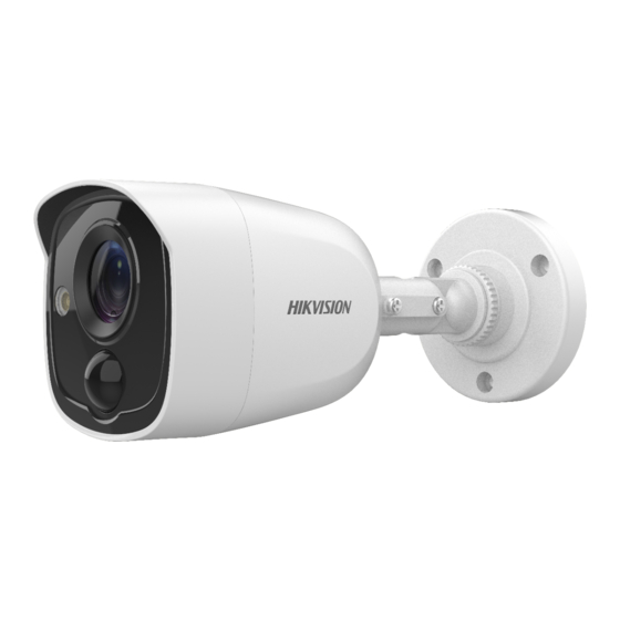
D8T PIR Series Bullet
Camera
User Manual
User Manual
Thank you for purchasing our product. If there are any
questions, or requests, do not hesitate to contact the
dealer.
This manual applies to the models below:
Type
Type I Camera
Type II Camera
This manual may contain several technical incorrect
places or printing errors, and the content is subject to
change without notice. The updates will be added to
the new version of this manual. We will readily improve
or update the products or procedures described in the
manual.
Model
DS-2CE11D8T-PIRL
DS-2CE12D8T-PIRL
0100001071019
Advertisement
Table of Contents

Related Manuals for HIKVISION DS-2CE11D8T-PIRL

Summary of Contents for HIKVISION DS-2CE11D8T-PIRL
- Page 1 This manual applies to the models below: Type Model Type I Camera DS-2CE11D8T-PIRL Type II Camera DS-2CE12D8T-PIRL This manual may contain several technical incorrect places or printing errors, and the content is subject to change without notice. The updates will be added to the new version of this manual.
-
Page 2: Regulatory Information
Regulatory Information FCC Information Please take attention that changes or modification not expressly approved by the party responsible for compliance could void the user’s authority to operate the equipment. FCC compliance: This equipment has been tested and found to comply with the limits for a Class A digital device, pursuant to part 15 of the FCC Rules. - Page 3 Safety Instruction These instructions are intended to ensure that user can use the product correctly to avoid danger or property loss. The precaution measure is divided into “Warnings” and “Cautions”. Warnings: Serious injury or death may occur if any of the warnings are neglected.
- Page 4 Keep the camera away from liquid while in use for non-water-proof device. While in delivery, the camera shall be packed in its original packing, or packing of the same texture. Mark Description Table 0-1 Mark Description Mark Description DC Voltage 1 Introduction 1.1 Product Features...
-
Page 5: Installation
2 Installation Before you start Make sure that the device in the package is in good condition and all the assembly parts are included. Make sure that all the related equipment is power-off during the installation. Check the specification of the products for the ... - Page 6 For cement wall/ceiling, expansion bolts are required to fix the camera. For wooden wall/ceiling, self-tapping screws are required. 4. Route the cables through the cable hole, or the side opening. 5. Connect the corresponding power cord, and video cable. 6.
- Page 7 Figure 2-5 Fix the Camera on the Junction Box’s Cover 5. Attach the junction box body to the ceiling/wall by aligning the screw holes of the junction box. 6. Secure the junction box’s body with supplied screws on the ceiling/wall. Figure 2-6 Fix the Junction Box to the Wall/Ceiling 7.
- Page 8 Figure 2-8 Drill Template Note: Drill the cable hole in the center of the drill template, when adopting ceiling outlet to route the cable. 3. Route the cables through the cable hole (optional) or the side opening. 4. Fix the camera to the ceiling with supplied screws. Figure 2-9 Fix the Camera to the Ceiling Note: The supplied screw package contains self-tapping...
- Page 9 2. Drill screw holes and the cable hole (optional) in the ceiling/wall according to the holes of the drill template. Figure 2-11 Drill Template Note: Drill the cable hole, when adopting ceiling outlet to route the cable. 3. Take apart the junction box, and align the screw holes of the bullet camera with those on the Junction box’s cover.
-
Page 10: Menu Description
3 Menu Description Purpose: Call the menu by clicking button on the PTZ Control interface, or call the preset No.95. Steps: 1. Connect the camera with the TVI DVR, and the monitor, shown as the figure 3-1. Figure 3-1 Connection 2. -
Page 11: White Light
3.2 LANGUAGE Supports English, and Chinese. 3.3 WHITE LIGHT The embedded white light source can be worked as the visible alarm, or the lighting. In the WHITE MODE, you can set the mode as ALARM, LIGHTING, or OFF. 3.3.1 ALARM In the ALARM mode, you can select the TRIGGER MODE as DVR, or CAMERA. - Page 12 BLC (Backlight Compensation) BLC (Backlight Compensation) compensates light to the object in the front to make it clear, but this may cause the over-exposure of the background where the light is strong. When BLC is selected as the exposure mode, the BLC level can be adjusted from 0 to 8.
- Page 13 DAY NIGHT AUTO MODE INFRARED SMART IR RETURN Figure 3-5 DAY NIGHT INFRARED You can turn on/off the infrared to meet the requirements of different circumstances. SMART IR The Smart IR function is used to adjust the light to its most suitable intensity, and prevent the image from over exposure.
-
Page 14: Save And Exit
Figure 3-7 PRIVACY Select a PRIVACY area. Set the DISPLAY status as ON. Click up/down/left/down button to define the position, and the size of the area. MOTION In the user-defined motion detection surveillance area, the moving object can be detected and the alarm will be triggered.