Table of Contents
Advertisement
M910x
User Guide and
Hardware Maintenance Manual
Machine Type (MT):
10MY, 10N0, 10N1, 10N2, 10QQ
Energy Star MT:
10MY, 10N0, 10N1, 10N2, 10QQ
Overview
Locations of indicators,
connectors, and
controls provided on
your computer
Replaceable parts
Locations of the
replaceable parts on
your computer
Computer locks
Locking devices for
your computer
Replacing CRUs
Replacing instructions
for customer-
replaceable units
(CRUs)
Specifications
Specifications of your
computer
Replacing FRUs
Replacing instructions
for field-replaceable
units (FRUs) (for
technicians only)
Advertisement
Table of Contents

Related Manuals for Lenovo ThinkCentre M910x


Summary of Contents for Lenovo ThinkCentre M910x
- Page 1 M910x User Guide and Hardware Maintenance Manual Machine Type (MT): 10MY, 10N0, 10N1, 10N2, 10QQ Energy Star MT: 10MY, 10N0, 10N1, 10N2, 10QQ Overview Computer locks Specifications Locations of indicators, Locking devices for Specifications of your connectors, and your computer computer controls provided on your computer...
-
Page 2: Table Of Contents
Contents Overview .........3 Replacing the external I/O box ........26 Replacing the power adapter bracket ....27 Front view ............... 3 Removing the computer cover ........28 Rear view ................ 4 Replacing the storage drive ........29 System board ..............6 Replacing the internal speaker ........30 Machine type and model label ........ -
Page 3: Overview
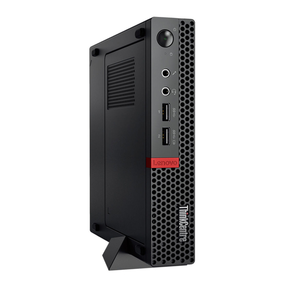
Overview Front view Note Your computer model might look slightly different from the illustration. Power indicator This indicator is on when the computer is on. Power button Used to turn on your computer. When you cannot shut down the computer from the operating system, press and hold the power button for four or more seconds to turn off the computer. -
Page 4: Rear View
Rear view Note Your computer model might look slightly different from the illustration. Mini DisplayPort® connectors (4) (optional) Used to send or receive audio and video signals. You can attach a compatible audio or video device to this connector, such as a high-performance monitor. - Page 5 USB 3.0 connector Used to connect a device that requires a USB 2.0 or USB 3.0 connection. DisplayPort connector Used to send or receive audio and video signals. You can attach a compatible audio or video device to this connector, such as a high-performance monitor.
-
Page 6: System Board
System board Note Front view Rear view for additional component descriptions. Serial connector 1 Serial connector 2 USB 3.0 connector Storage drive fan connector Microprocessor socket Coin-cell battery Illuminated red dot connector Internal speaker connector System fan connector Advanced speaker connector SATA storage drive connector M.2 Wi-Fi card slot PCI Express graphics card slot... -
Page 7: Machine Type And Model Label
Machine type and model label The machine type and model label identifies your computer. When you contact Lenovo for help, the machine type and model information helps support technicians to identify your computer and provide faster service. The machine type and model label is attached on the side of your computer as shown. -
Page 8: I/O Box
I/O box Overview Note Depending on your computer model, the I/O box might be optional. USB 2.0 connectors (2) Serial connector (optional) USB 2.0 connectors (2) USB 3.0 connectors (2) USB 3.0 connector (for connecting to the computer) I/O box... -
Page 9: Using The I/O Box
Using the I/O box When you use the I/O box with the ThinkCentre tiny computer, note the following: • The I/O box supports a maximum current rating of 5 A. It is recommended that you connect low-current devices to the I/O box and connect high-current devices directly to the ThinkCentre tiny computer to ensure the best performance of the devices. -
Page 10: Computer Locks
Depending on the type selected, the cable lock can be operated with a key or combination. The cable lock also locks the buttons used to open the computer cover. This is the same type of lock used with many notebook computers. You can order such a cable lock directly from Lenovo by searching for Kensington at: http://www.lenovo.com/support. -
Page 11: Specifications
Specifications Power supply 135 watt automatic voltage-sensing power supply Storage drives Up to three storage drives Video features The integrated graphics card supports the following: • DisplayPort connectors Audio features The integrated audio card supports the following: • Advanced speaker (optional) •... -
Page 12: Replacing Hardware
• In most areas of the world, Lenovo requires the return of defective CRUs (Customer Replaceable Units). Information about this will come with the CRU or will come a few days after the CRU arrives. -
Page 13: Knowing Replaceable Parts
CRU. Optional-service CRUs can be removed and installed by users or, during the warranty period, by a Lenovo service technician. Field-Replaceable Units (FRUs) FRUs are computer parts that a trained technician can upgrade or replace. -
Page 14: Crus And Frus Locations
CRUs and FRUs locations Refer to the following illustrations to check the locations of CRUs and FRUs within the computer. • Some of the following parts might look different from the one illustrated. Note • Some of the following parts are optional on some models. Self-service CRU Vertical stand p. - Page 15 Optional-service CRU Internal speaker p. 30 System fan p. 31 Storage drive p. 29 Storage drive bracket p. 29 Wi-Fi card shield p. 34 Wi-Fi card p. 34 PCI Express card p. 32 PCI Express card adapter p. 32 Replacing hardware...
- Page 16 Microprocessor p. 50 Coin-cell battery p. 52 Illuminated red dot cable p. 43 Advanced speaker p. 44 Antenna bracket p. 54 System board p. 55 Chassis p. 55 Storage drive cable p. 48 Wi-Fi antennas p. 45 Heat sink p. 49 Replacing hardware...
-
Page 17: Replacing Crus
Replacing CRUs Before replacing CRUs Customer Replaceable Units (CRUs) are computer parts that a user can upgrade or replace. There are two types of CRUs: self-service and optional-service. To check the locations of CRUs, see CRUs and FRUs locations. Do not open your computer or attempt any repairs before reading the Important Attention Product Information Guide. - Page 18 PCI Express card Wi-Fi card adapter Bottom cover Memory module M.2 storage drive To replace a component that is not in the list above, contact a Lenovo service Note technician. The support phone numbers are available at http://www.lenovo.com/ support/phone. Replacing CRUs...
-
Page 19: Replacing The Keyboard Or Wireless Keyboard
Replacing the keyboard or wireless keyboard Note The wireless keyboard is available only on some models. Replacing the keyboard Turn off the computer and disconnect all power cords from electrical outlets. Disconnect the old keyboard cable from the computer. Connect a new keyboard to the appropriate connector on the computer. Replacing the wireless keyboard Remove your old wireless keyboard. -
Page 20: Replacing The Mouse Or Wireless Mouse
Replacing the mouse or wireless mouse Note The wireless mouse is available only on some models. Replacing the mouse Turn off the computer and disconnect all power cords from electrical outlets. Disconnect the old mouse cable from the computer. Connect a new mouse to the appropriate connector on the computer. Replacing the wireless mouse Disconnect the USB dongle from your computer. - Page 21 • The green LED indicates that the mouse is ready for use. Note • The flashing amber LED indicates a low battery level. • Push the power switch to the off position when you are not using the mouse to extend the battery life.
-
Page 22: Replacing The Power Adapter
Replacing the power adapter Do not open your computer or attempt any repairs before reading the Important Attention Product Information Guide. Remove any media from the drives and turn off all connected devices and the computer. Disconnect all power cords from electrical outlets and disconnect all cables that are connected to the computer. -
Page 23: Replacing The Vertical Stand
Replacing the vertical stand Do not open your computer or attempt any repairs before reading the Important Attention Product Information Guide. Remove any media from the drives and turn off all connected devices and the computer. Disconnect all power cords from electrical outlets and disconnect all cables that are connected to the computer. -
Page 24: Replacing The Vesa Mount Bracket
Replacing the VESA mount bracket Do not open your computer or attempt any repairs before reading the Important Attention Product Information Guide. Remove any media from the drives and turn off all connected devices and the computer. Disconnect all power cords from electrical outlets and disconnect all cables that are connected to the computer. -
Page 25: Replacing The External Optical Drive
Replacing the external optical drive Do not open your computer or attempt any repairs before reading the Important Attention Product Information Guide. Remove any media from the drives and turn off all connected devices and the computer. Disconnect all power cords from electrical outlets and disconnect all cables that are connected to the computer. -
Page 26: Replacing The External I/O Box
Replacing the external I/O box Do not open your computer or attempt any repairs before reading the Important Attention Product Information Guide. Remove any media from the drives and turn off all connected devices and the computer. Disconnect all power cords from electrical outlets and disconnect all cables that are connected to the computer and the external I/O box. -
Page 27: Replacing The Power Adapter Bracket
Replacing the power adapter bracket Do not open your computer or attempt any repairs before reading the Important Attention Product Information Guide. Remove any media from the drives and turn off all connected devices and the computer. Disconnect all power cords from electrical outlets and disconnect all cables that are connected to the computer. -
Page 28: Removing The Computer Cover
Removing the computer cover Do not open your computer or attempt any repairs before reading the Important Attention Product Information Guide. Remove any media from the drives and turn off all connected devices and the computer. Disconnect all power cords from electrical outlets and disconnect all cables that are connected to the computer. -
Page 29: Replacing The Storage Drive
Replacing the storage drive Do not open your computer or attempt any repairs before reading the Important Attention Product Information Guide. Remove any media from the drives and turn off all connected devices and the computer. Disconnect all power cords from electrical outlets and disconnect all cables that are connected to the computer. -
Page 30: Replacing The Internal Speaker
Replacing the internal speaker Do not open your computer or attempt any repairs before reading the Important Attention Product Information Guide. Remove any media from the drives and turn off all connected devices and the computer. Disconnect all power cords from electrical outlets and disconnect all cables that are connected to the computer. -
Page 31: Replacing The System Fan
Replacing the system fan Do not open your computer or attempt any repairs before reading the Important Attention Product Information Guide. Remove any media from the drives and turn off all connected devices and the computer. Disconnect all power cords from electrical outlets and disconnect all cables that are connected to the computer. -
Page 32: Replacing The Pci Express Card And Pci Express Card Adapter
Replacing the PCI Express card and PCI Express card adapter Do not open your computer or attempt any repairs before reading the Important Attention Product Information Guide. Remove any media from the drives and turn off all connected devices and the computer. Disconnect all power cords from electrical outlets and disconnect all cables that are connected to the computer. - Page 33 Reinstall the computer cover and reconnect the cables. For details, see Completing the parts replacement. Replacing CRUs...
-
Page 34: Replacing The Wi-Fi Card
Replacing the Wi-Fi card Do not open your computer or attempt any repairs before reading the Important Attention Product Information Guide. Remove any media from the drives and turn off all connected devices and the computer. Disconnect all power cords from electrical outlets and disconnect all cables that are connected to the computer. - Page 35 • Type 2 Replacing CRUs...
- Page 36 Reinstall the computer cover and reconnect the cables. For details, see Completing the parts replacement. Replacing CRUs...
-
Page 37: Replacing The Bottom Cover
Replacing the bottom cover Do not open your computer or attempt any repairs before reading the Important Attention Product Information Guide. Remove any media from the drives and turn off all connected devices and the computer. Disconnect all power cords from electrical outlets and disconnect all cables that are connected to the computer. -
Page 38: Replacing The Memory Module
Replacing the memory module Do not open your computer or attempt any repairs before reading the Important Attention Product Information Guide. If your computer supports one memory module, install the module into the DIMM 1 slot. If your computer supports two memory modules, install one memory module into the DIMM 1 slot first and then install the other into the DIMM 2 slot. -
Page 39: Replacing The M.2 Storage Drive
Replacing the M.2 storage drive Do not open your computer or attempt any repairs before reading the Important Attention Product Information Guide. If your computer supports one M.2 storage drive, install the drive into the M.2 storage drive slot 1. If your computer supports two M.2 storage drives, install one drive into the M.2 storage drive slot 1 first and then install the other into the slot 2. -
Page 40: Completing The Parts Replacement
Completing the parts replacement After completing the installation or replacement for all parts, reinstall the computer cover and reconnect the cables. To reinstall the computer cover and reconnect the cables to your computer, do the following: Ensure that all components have been reassembled correctly and that no tools or loose screws are left inside your computer. -
Page 41: Replacing Frus
• Replace an FRU only with another FRU of the correct model. When you replace an FRU, ensure that the model of the machine and the FRU part number are correct by referring to the website http://www.lenovo.com/serviceparts-lookup. • An FRU should not be replaced because of a single, unreproducible failure. - Page 42 Storage drive cable Heat sink Microprocessor Coin-cell battery Antenna bracket System board Chassis To replace a component that is not in Note the list above, contact a Lenovo service technician. The support phone numbers are available at http://www.lenovo.com/support/phone. Replacing FRUs...
-
Page 43: Replacing The Illuminated Red Dot Cable
Replacing the illuminated red dot cable Do not open your computer or attempt any repairs before reading the Important Attention Product Information Guide. Remove the computer cover. For details, see Removing the computer cover. Disconnect the illuminated red dot cable from the system board. See System board. ... -
Page 44: Replacing The Advanced Speaker
Replacing the advanced speaker Note The advanced speaker is available only on some models. Do not open your computer or attempt any repairs before reading the Important Attention Product Information Guide. Remove the computer cover. For details, see Removing the computer cover. Remove the storage drive. -
Page 45: Replacing The Wi-Fi Antennas
Replacing the Wi-Fi antennas Do not open your computer or attempt any repairs before reading the Important Attention Product Information Guide. Replacing the front Wi-Fi antenna Remove the computer cover. For details, see Removing the computer cover. Remove the storage drive. For details, see Replacing the storage drive. ... -
Page 46: Replacing The Rear Wi-Fi Antenna
Replacing the rear Wi-Fi antenna Remove the computer cover. For details, see Removing the computer cover. Remove the storage drive. For details, see Replacing the storage drive. Remove the system fan. For details, see Replacing the system fan. Remove the PCI Express card. For details, see Replacing the PCI Express card and PCI Express card adapter. ... - Page 47 Connect the rear Wi-Fi antenna cable to the Wi-Fi card. Reinstall the removed parts and computer cover. For details, see Completing the parts replacement. Replacing FRUs...
-
Page 48: Replacing The Storage Drive Cable
Replacing the storage drive cable Do not open your computer or attempt any repairs before reading the Important Attention Product Information Guide. Remove the computer cover. For details, see Removing the computer cover. Remove the storage drive. For details, see Replacing the storage drive. ... -
Page 49: Replacing The Heat Sink
Replacing the heat sink Do not open your computer or attempt any repairs before reading the Important Attention Product Information Guide. Remove the computer cover. For details, see Removing the computer cover. Remove the storage drive. For details, see Replacing the storage drive. Remove the internal speaker. -
Page 50: Replacing The Microprocessor
Replacing the microprocessor Do not open your computer or attempt any repairs before reading the Important Attention Product Information Guide. The heat sink and microprocessor might be very hot. Before you open the computer Caution cover, turn off the computer and wait several minutes until the computer is cool. Remove the computer cover. - Page 51 Reinstall the removed parts and computer cover. For details, see Completing the parts replacement. Replacing FRUs...
-
Page 52: Replacing The Coin-Cell Battery
Replacing the coin-cell battery Do not open your computer or attempt any repairs before reading the Important Attention Product Information Guide. Your computer has a special type of memory that maintains the date, time, and settings for built- in features, such as parallel connector assignments (configurations). A coin-cell battery keeps this information active when you turn off the computer. - Page 53 Replace the coin-cell battery. Reinstall the removed parts and computer cover. For details, see Completing the parts replacement. To dispose of the coin-cell battery, refer to the “Lithium coin-cell battery notice” topic in the Safety and Warranty Guide. Replacing FRUs...
-
Page 54: Replacing The Antenna Bracket
Replacing the antenna bracket Do not open your computer or attempt any repairs before reading the Important Attention Product Information Guide. Remove the computer cover. For details, see Removing the computer cover. Remove the storage drive. For details, see Replacing the storage drive. Remove the internal speaker. -
Page 55: Replacing The System Board And Chassis
Replacing the system board and chassis Do not open your computer or attempt any repairs before reading the Important Attention Product Information Guide. Remove the computer cover. For details, see Removing the computer cover. Remove the storage drive. For details, see Replacing the storage drive. ... - Page 56 Replace the system board and chassis. Note Carefully handle the system board by its edges. Route all the cables that you disconnected from the failing system board, and then reconnect the cables to the new system board. See System board. Reinstall the removed parts and computer cover.
-
Page 57: Notices & Trademarks
Any warranties in certain transactions, therefore, this reference to a Lenovo product, program, or service statement may not apply to you. is not intended to state or imply that only that Lenovo product, program, or service may be used. -
Page 58: Trademarks
Web sites. The materials at those Web Electronics Standards Association. sites are not part of the materials for this Lenovo VESA is a Trademark of the Video Electronics product, and use of those Web sites is at your own Standards Association.