Panasonic VL-SWD273 Installation Manual
Hide thumbs
Also See for VL-SWD273:
- Important information and quick manual (16 pages) ,
- Quick start manual (2 pages)
Advertisement
Quick Links
R This guide is for use with the above 3 models.
R The Installation Guide in Indonesian can be accessed from the following site:
https://panasonic.net/cns/pcc/support/intercom/swd273
R Door station is described as "doorphone" and Main monitor station is described as "main
monitor" in this guide.
R In this guide, the suffix of each model number (e.g., the "BX" in "VL-MWD273BX") is omitted
unless necessary.
Note to the installer
R Before attempting to connect or operate this product, please read the label on the rear of
the doorphone and the main monitor/extension monitor.
R Please read this guide carefully, and install the product safely and correctly by following
the instructions. Carefully read the information found in the section titled "For your
safety" in particular.
R Only use attachments/accessories specified by the manufacturer.
R The installation shall be carried out in accordance with all applicable installation rules.
R
To the maximum extent permitted by law, Panasonic assumes no responsibility for
injuries or property damage resulting from failures arising out of improper installation or
operation inconsistent with this document.
R After installation, make sure to leave this guide with the customer.
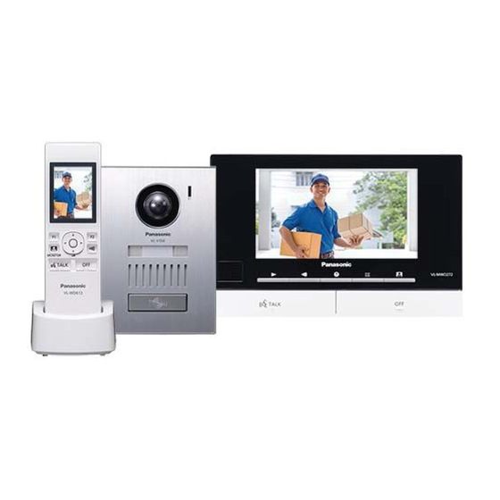
Model Name
Wireless Video Intercom System
Video Intercom System
Main Monitor Station
VL-V554
Door station
Installation Guide
VL-MWD273
Main monitor station
Model No.
Model No.
VL-SWD273
VL-SVD273
VL-MWD273
Advertisement

Related Manuals for Panasonic VL-SWD273


Summary of Contents for Panasonic VL-SWD273
- Page 1 R Only use attachments/accessories specified by the manufacturer. R The installation shall be carried out in accordance with all applicable installation rules. To the maximum extent permitted by law, Panasonic assumes no responsibility for injuries or property damage resulting from failures arising out of improper installation or operation inconsistent with this document.
-
Page 2: For Your Safety
RDo not use the supplied power supply For your safety unit for outdoor installations (it is for indoor use only). To prevent severe injury and loss of life/ RDo not install the main monitor/ property, read this section carefully extension monitor in the following before using the product to ensure places: proper and safe operation of your... -
Page 3: Preventing Injury
may cause such devices to RIf the wiring is outdoors, use a malfunction, resulting in an accident. protection tube or a surge protector. Preventing injury CAUTION Install the product securely adhering to the instructions in this guide to Preventing electric shock prevent it from falling off the wall. -
Page 4: Precautions For Installation
[Locally procured] – Power cables (AC/DC cables), wires (for doorphone and other connections): Prepare wires of the appropriate specification. (a"Wire type and length") Note: R The illustrations in the supplied manual(s) may vary slightly from the actual product. *1 VL-SWD273AZ/VL-SVD273AZ models only *2 VL-MWD273BX/VL-MWD273ML models only *3 VL-SWD273AZ/VL-SVD273AZ/VL-MWD273AZ models only Precautions for installation... - Page 5 Wiring schematic diagram Set up correctly according to the following wiring schematic diagram and "Wire type and length". R For information, such as order numbers, about optional devices that can be connected to, refer to the "Additional/replacement accessories" section in the Operating Instructions. DOORPHONE 1 DOORPHONE 2 D1 D2 S1 S2...
- Page 6 Wire type and length Wire type Wiring run Diameter Length (Max.) ø 0.65 mm 22 AWG 100 m Doorphone – Main monitor – ø 1.0 mm 18 AWG 130 m Extension monitor ø 0.5 mm CAT 5 50 m ø 0.65 mm 22 AWG 10 m Main monitor –...
- Page 7 Connecting an optional lobby station VL-V590 Lobby station MAIN MONITOR <Rear view> Ml-1 Ml-2 MO-1 MO-2 MO-3 MO-4 MO-5 MO-6 NP: Non-polarised <Be sure to perform the following to ensure proper operation> R Connecting an optional VL-V590 lobby station – Connect terminal D1/D2 on the main monitor with terminal D1/D2 on the lobby station. –...
- Page 8 Doorphone installation position Installation height and area visible by the camera lens (when connected to VL-SWD273 series) You can use the [Wide/Zoom settings] setting on the main monitor to select the area that is visible when a visitor calls; available settings are [Wide] and [Zoom]. (Default setting: [Wide]) R The following values are for when the doorphone is installed in the standard position (the centre of the doorphone’s height is approximately 1450 mm) and the visitor is approximately 500 mm away from the...
- Page 9 Up and down Left and right (when looking from above) (Units: mm) (Units: mm) Left A Image range B Approx. 55° C Center of A Image range: Approx. 900 B Approx. 500 doorphone D Approx. 1450 E Approx. 500 C Approx. 85° D Approx. 170° F Approx.
- Page 10 When using mounting box (option): Installing the doorphone Model No. VL-MB554 Install the flush mounting box (A) in the Important: wall. R On the bottom surface of the doorphone and the mounting base, there are holes to allow water to drain.
- Page 11 Connect the wires. When using mounting box (option): Loosen the screws. Push in the wires to the Model No. VL-MB554 terminal connectors (non-polar), then tighten Attach the doorphone to the flush mounting box. the screws (A, B). A Terminal for the main monitor B Terminal for the electric lock –...
- Page 12 Power supply unit (with cable covers Installing the power supply removed) Top view Bottom view unit (VL-MWD273BX, VL- MWD273ML models only) About the installation location R The device must be installed inside an electrical panel or cabinet. R A readily accessible disconnect device shall be incorporated external to the equipment.
-
Page 13: Installing The Power Supply Unit
Power supply unit (with cable cover removed) Installing the power supply Top view Bottom view unit (VL-SWD273AZ, VL- SVD273AZ, VL-MWD273AZ models only) About the installation location R The AC cable plug is used as the main K DC cable binder hole disconnect device. - Page 14 Main monitor/extension Installing the main monitor/ monitor installation position extension monitor About the installation position of the main Attach the mounting bracket (A) to the wall monitor/extension monitor and mounting securely. bracket R Install the mounting bracket on a vertical flat R Place the main monitor/extension monitor in a wall (B).
- Page 15 2-2 How to make wiring connections monitor, and push the main monitor/extension While pressing on the button (F) with a monitor down until it is secure. pointed object such as a screwdriver, insert the wire into the terminal connector (G). (To disconnect a wire, pull out the wire while pressing on the button (F).) Notes about electrical wiring...
- Page 16 1006, Oaza Kadoma, Kadoma-shi, Osaka 571-8501, Japan http://www.panasonic.com © Panasonic Corporation 2017 PNQX8466ZA C0417MM0...