Table of Contents
Advertisement
Quick Links
Advertisement
Chapters
Table of Contents

Related Manuals for Lenovo E470


Summary of Contents for Lenovo E470
- Page 1 E470, E470c, and E475 Hardware Maintenance Manual...
- Page 2 Appendix A “Notices” on page 93. Third Edition (July 2017) © Copyright Lenovo 2016, 2017. LIMITED AND RESTRICTED RIGHTS NOTICE: If data or software is delivered pursuant to a General Services Administration “GSA” contract, use, reproduction, or disclosure is subject to restrictions set forth in Contract No. GS-...
-
Page 3: Table Of Contents
Checkout guide ....Chapter 6. Function keys ..47 Lenovo Companion ... Quick test programs ... - Page 4 1090 Speaker assembly ... Appendix B. Abbreviation table ..95 1110 System board and thermal fan assembly . . . E470, E470c, and E475 Hardware Maintenance Manual...
-
Page 5: About This Manual
Use this manual along with the advanced diagnostic tests to troubleshoot problems effectively. Before servicing a ThinkPad product, be sure to read all the information under Chapter 1 “Safety information” on page 1 and Chapter 2 “Important service information” on page 21. © Copyright Lenovo 2016, 2017... - Page 6 E470, E470c, and E475 Hardware Maintenance Manual...
-
Page 7: Chapter 1. Safety Information
Do not use this type of mat to protect yourself from electrical shock. © Copyright Lenovo 2016, 2017... -
Page 8: Safety Inspection Guide
If any unsafe conditions are present, you must determine how serious the apparent hazard could be and whether you can continue without first correcting the problem. E470, E470c, and E475 Hardware Maintenance Manual... -
Page 9: Handling Devices That Are Sensitive To Electrostatic Discharge
0.1 ohm or less between the external ground pin and the frame ground. b. The power cord should be the authorized type specified for your computer. Go to: http:// www.lenovo.com/serviceparts-lookup c. Insulation must not be frayed or worn. 4. Check for cracked or bulging batteries. -
Page 10: Grounding Requirements
The safety notices in this section are provided in the following languages: • English • Arabic • Brazilian Portuguese • French • German • Hebrew • Japanese • Korean • Spanish • Traditional Chinese DANGER DANGER DANGER E470, E470c, and E475 Hardware Maintenance Manual... - Page 11 DANGER DANGER DANGER DANGER DANGER Chapter 1 Safety information...
- Page 12 E470, E470c, and E475 Hardware Maintenance Manual...
- Page 13 PERIGO PERIGO Chapter 1 Safety information...
- Page 14 PERIGO PERIGO PERIGO PERIGO PERIGO E470, E470c, and E475 Hardware Maintenance Manual...
- Page 15 PERIGO DANGER DANGER DANGER DANGER Chapter 1 Safety information...
- Page 16 DANGER DANGER DANGER DANGER VORSICHT E470, E470c, and E475 Hardware Maintenance Manual...
- Page 17 VORSICHT VORSICHT VORSICHT VORSICHT Chapter 1 Safety information...
- Page 18 VORSICHT VORSICHT VORSICHT E470, E470c, and E475 Hardware Maintenance Manual...
- Page 19 Chapter 1 Safety information...
- Page 20 E470, E470c, and E475 Hardware Maintenance Manual...
- Page 21 Chapter 1 Safety information...
- Page 22 E470, E470c, and E475 Hardware Maintenance Manual...
- Page 23 Chapter 1 Safety information...
- Page 24 E470, E470c, and E475 Hardware Maintenance Manual...
- Page 25 Chapter 1 Safety information...
- Page 26 E470, E470c, and E475 Hardware Maintenance Manual...
-
Page 27: Chapter 2. Important Service Information
UEFI BIOS downloads. Telephone numbers for Lenovo Support are available at: http://www.lenovo.com/support/phone • System Disassembly/Reassembly videos that show the FRU removals or replacements for the Lenovo authorized service technicians are available in the following support site: http://www.lenovoservicetraining.com/ion/... -
Page 28: Important Notice For Replacing A System Board
Dynamic Configure To Order (CTO) This model provides the ability for a customer to configure a Lenovo solution from a web site, and have this configuration sent to fulfillment, where it is built and shipped directly to the customer. The machine label and eSupport will load these products as the 4-character MT, 4-character model and 2-character country code. -
Page 29: Fru Identification
20AA0009UK). FRU identification Use Lenovo eSupport to identify major FRUs, FRU part numbers, and FRU descriptions for a product at an MT - serial number level. Examples of major FRUs are hard disk drive, system board, liquid crystal display (LCD), and memory module. - Page 30 E470, E470c, and E475 Hardware Maintenance Manual...
-
Page 31: Chapter 3. General Checkout
This chapter introduces following information: • “What to do first” on page 25 • “Checkout guide” on page 26 – “Lenovo Companion” on page 26 – “Quick test programs” on page 26 – “UEFI diagnostic program” on page 27 – “Bootable diagnostic programs” on page 28 •... -
Page 32: Checkout Guide
Lenovo Companion is preinstalled on the computer and also is available for download at: https://shop.lenovo.com/us/en/accessories/software/apps/lenovo-apps/companion/ To run the Lenovo Companion program, open the Start menu and click Lenovo Companion, and then follow the instructions on the screen. For additional information, see the help system of the program. -
Page 33: Uefi Diagnostic Program
• Lenovo Wireless Quick Test • Lenovo PCI Express Quick Test • Lenovo RAID Quick Test • Lenovo Motherboard Bus Quick Test The quick test programs are applicable on the following operating systems: ® ® • Microsoft Windows • Microsoft Windows 8.1 •... -
Page 34: Bootable Diagnostic Programs
If the computer you are servicing is not installed with the UEFI diagnostic program, you can download a bootable diagnostic program from the Lenovo Support Web site. The bootable diagnostic programs enable you to test computer memory and internal storage devices, view system information, and check and recover the internal storage devices. -
Page 35: Power System Checkout
This computer supports only batteries specially designed for this specific system and manufactured by Lenovo or an authorized builder. The system does not support unauthorized batteries or batteries designed for other systems. If an unauthorized battery or a battery designed for another systems is installed, the system will not charge. -
Page 36: Checking The Coin-Cell Battery
Attention: Lenovo has no responsibility for the performance or safety of unauthorized batteries, and provides no warranties for failures or damage arising out of their use. The battery status icon in the Windows notification area displays the percentage of the remaining battery power. -
Page 37: Chapter 4. Related Service Information
If you did not create recovery media as a precautionary measure, you can contact Lenovo Customer Support Center and purchase a set of recovery media from Lenovo. For a list of the Lenovo Support phone numbers for your country or region, go to: http://www.lenovo.com/support/phone... -
Page 38: Reinstalling Preinstalled Programs And Device Drivers
• If the device subfolder contains a readme TXT file, the device driver installation information is included in the readme file. Follow the instructions to complete the installation. E470, E470c, and E475 Hardware Maintenance Manual... -
Page 39: Restoring The Factory Contents By Using The Recovery Disc Set
• If the device subfolder contains an INF file, right-click the INF file and select Install. Then follow the instructions on the screen to complete the installation. If you need updated device drivers for your computer, download and install them from the Lenovo Support Web site at: http://www.lenovo.com/support... -
Page 40: Recovery Overview For The Windows 10 Operating System
1. Open the Start menu and then click Settings ➙ Update & security ➙ Recovery. 2. In the Advanced startup section, click Restart now ➙ Troubleshoot ➙ Advanced options. 3. Select a desired startup option, then follow the instructions on the screen. E470, E470c, and E475 Hardware Maintenance Manual... -
Page 41: Recovering Your Operating System If Windows 10 Fails To Start
Recovering your operating system if Windows 10 fails to start The Windows recovery environment on your computer is capable of operating independently from the Windows 10 operating system. This enables you to recover or repair the operating system even if the Windows 10 operating system fails to start. -
Page 42: Power-On Password
If it has, it can be used for access to the hard disk drive. If no master hard disk password is available, neither Lenovo nor Lenovo authorized service technicians provide any services to reset either the user or the master hard disk password, or to recover data from the hard disk drive. The hard disk drive can be replaced for a scheduled fee. -
Page 43: How To Remove The Hard Disk Password
To put the system back to operational status, the only Lenovo and Lenovo-authorized service solution would be to replace the hard disk drive, hybrid drive, or solid-state drive with a scheduled fee. -
Page 44: Screen Blank Mode (For The Windows 7 Operating System Only)
If you do undock it and then try to resume normal operation, you will get an error message, and you will have to restart the system. E470, E470c, and E475 Hardware Maintenance Manual... -
Page 45: Symptom-To-Fru Index
If you have defined one of the following actions as the event that causes the system to go into hibernation mode, perform that action. • Closing the lid. • Pressing the power button. Also, the computer goes into hibernation mode automatically after a period of inactivity specified in power plan settings. - Page 46 Read error on HDD1 (Mini SATA) 2. Replace the mini SATA device. 3. Replace the system board. 2200 Replace the system board. Machine Type and Serial Number are invalid. 2201 Replace the system board. Machine UUID is invalid E470, E470c, and E475 Hardware Maintenance Manual...
-
Page 47: Error Messages
Thermal sensing error. Replace the system board. This system does not support batteries that are not Replace the battery. genuine Lenovo-made or authorized. The system will continue to boot, but may not charge unauthorized batteries. Attention: Lenovo has no responsibility for the... -
Page 48: Lcd-Related Symptoms
LCD technology, but excessive pixel problems can cause viewing concerns.If the LCD you are servicing has two or less visible defective pixels, it should not be considered faulty. However, if the LCD has three or more visible defective pixels, it will be deemed as defective by Lenovo and it should be replaced. Notes: •... - Page 49 3. Remove or disconnect all of the following devices: a. Non-ThinkPad devices b. Devices attached to the docking station or the port replicator c. Printer, mouse, and other external devices d. Battery pack e. Hard disk drive, hybrid drive, or solid-state drive f.
- Page 50 E470, E470c, and E475 Hardware Maintenance Manual...
-
Page 51: Chapter 5. Status Indicators
Table 7. Status indicators Indicator Meaning Caps Lock indicator When this indicator is on, you can type uppercase letters by directly pressing the letter keys. Camera status indicator When this indicator is on, the camera is in use. © Copyright Lenovo 2016, 2017... - Page 52 This indicator shows the ac power and charging status of the computer. • Green: connected to ac power (charging 90%–100%) • Yellow: connected to ac power (charging 0%–90%) • Off: not connected to ac power (no charging) E470, E470c, and E475 Hardware Maintenance Manual...
-
Page 53: Chapter 6. Function Keys
Manage external displays. Enable or disable the built-in wireless features. For Windows 7: Open Control Panel. For Windows 10: Open the Settings window. Enable or disable the built-in Bluetooth features. Open a keyboard setting page. © Copyright Lenovo 2016, 2017... - Page 54 1. Open Control Panel, and then change the view of Control Panel from Category to Large icons or Small icons. 2. Click Lenovo ➙ Keyboard Manager. In the Keyboard Manager window, click the USER-DEFINED KEY tab. On this setting page, you can also define different functions for the key combinations with F12, such as Shift+F12, Alt+F12, or Ctrl+F12.
-
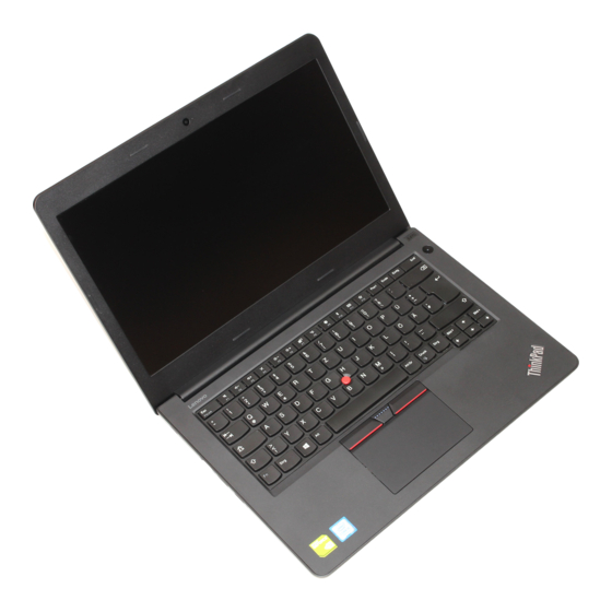
Page 55: Chapter 7. Locations
This topic helps you locate the controls, connectors, and indicators on your computer. Front view Microphones Camera Power button Security-lock slot USB 2.0 connector USB 3.0 connector Audio connector Media-card slot Fingerprint reader (available on some models) Trackpad ® TrackPoint buttons TrackPoint pointing stick © Copyright Lenovo 2016, 2017... -
Page 56: Bottom View
: Internal storage drive refers to the installed hard disk drive, solid-state drive, or hybrid drive. Rear view Fan louvers Locating FRUs and CRUs This topic introduces the following service parts: • “Major FRUs” on page 52 • “LCD FRUs” on page 54 E470, E470c, and E475 Hardware Maintenance Manual... - Page 57 CRUs, you can either install the CRU yourself or you can request that a Service Provider install the CRU according to the warranty service for your product. If you intend on installing the CRU, Lenovo will ship the CRU to you. CRU information and replacement instructions are shipped with your product and are available from Lenovo at any time upon request.
-
Page 58: Major Frus
Major FRUs E470, E470c, and E475 Hardware Maintenance Manual... - Page 59 Power cord ac power adapter Available on some models Note: The Lenovo factory recovery USB key and the Lenovo recovery disc set are used to restore the Microsoft Windows operating system. They might not come with the computer, and a user might order them from , though additional shipping and handling fees might apply.
-
Page 60: Lcd Frus
Table 10. LCD FRUs FRU descriptions Self-service Optional service LCD bezel assembly LCD panel LCD hinge assembly Camera and microphone combo card WLAN antenna assembly LCD rear cover assembly LCD/ThinkPad logo combo cable E470, E470c, and E475 Hardware Maintenance Manual... -
Page 61: Connector And Cable Guide
Connector and cable guide This topic provides information to help Lenovo authorized service technicians identify connectors and cables for replacement purpose. To view each FRU and the exploded illustration of the computer, see “Major FRUs” on page 52 and “LCD FRUs” on page 54. - Page 62 LCD panel connector and cable Table 12. LCD panel Ite- Connector (location) Internal cable required Cable connection LCD panel connector LCD cable Connect one end to this connector and the other end (internal) to the system board. E470, E470c, and E475 Hardware Maintenance Manual...
- Page 63 Camera/microphone combo card connector and cable Table 13. Camera/microphone combo card Connector (location) Internal cable required Cable connection Camera/microphone card Cable for camera and Connect one end to the LCD connector on the system, connector (internal) microphone combo card one end to the LCD connector on the LCD panel, and the other end to this connector.
-
Page 64: Looking Up Fru Information
Connect one end of the wireless-LAN black antenna to connector (internal) the A-cover and the other end to this connector. Looking up FRU information For detailed FRU information, including part numbers, descriptions, and substitution part numbers, go to: http://www.lenovo.com/serviceparts-lookup E470, E470c, and E475 Hardware Maintenance Manual... -
Page 65: Chapter 8. Fru Replacement Notices
CRU to you. CRU information and replacement instructions are shipped with your product and are available from Lenovo at any time upon request. You can find a list of CRUs for your product in this Hardware Maintenance Manual. An electronic version of this manual can be found at http://www.lenovo.com/support... -
Page 66: Retaining Serial Numbers
Maintenance Key. Note: Only an authorized Lenovo service technician can access the above Web site. 3. Restart the computer. 4. When the logo screen is displayed, press Esc. The ThinkPad Config Information Update Utility interface is displayed. -
Page 67: Retaining The Uuid
Maintenance key. Note: Only an authorized Lenovo service technician can access the above Web site. 3. Restart the computer. 4. When the logo screen is displayed, press Esc. The ThinkPad Config Information Update Utility interface is displayed. - Page 68 E470, E470c, and E475 Hardware Maintenance Manual...
-
Page 69: Chapter 9. Removing Or Replacing A Fru
CRU to you. CRU information and replacement instructions are shipped with your product and are available from Lenovo at any time upon request. You can find a list of CRUs for your product in this Hardware Maintenance Manual. An electronic version of this manual is available for downloading at http:// www.lenovo.com/support... -
Page 70: Before Servicing The Computer
Disconnect the battery Before replacing any FRU, ensure that you have disconnected the battery by doing the following: 1. Remove the screws , and then remove the bottom cover 2. Disconnect the battery E470, E470c, and E475 Hardware Maintenance Manual... -
Page 71: 1010 Bottom Cover
1010 Bottom cover Removal steps of the bottom cover Remove the screws , and then remove the bottom cover Step Screw (quantity) Color Torque Black 0.294 Nm M2 × 6.5 mm, flat-head, nylon-coated (3) (3.0 kgf-cm) Applying labels to the bottom cover The new bottom cover FRU is shipped with a kit containing labels of several kinds. -
Page 72: 1020 Internal Storage Drive
Brazil Anatel label Argentina CNC label Israel homologation label Indonesia Rating label FCC ID and IC label 1020 Internal storage drive For access, remove this FRU: • “1010 Bottom cover” on page 65 E470, E470c, and E475 Hardware Maintenance Manual... - Page 73 Attention: • Do not drop the drive or apply any physical shock to it. The drive is sensitive to physical shock. Improper handling can cause damage and permanent loss of data. • Before removing the drive, have the user make a backup copy of all the information on it if possible. •...
-
Page 74: 1030 Memory Module
Insert the notched end of the memory module into the memory slot. Press the memory module in firmly, and pivot it downward until it snaps into place. Ensure that the memory module is firmly installed in the slot and does not move easily. E470, E470c, and E475 Hardware Maintenance Manual... -
Page 75: 1040 Wireless Lan Card
1040 Wireless LAN card For access, remove this FRU: • “1010 Bottom cover” on page 65 Removal steps of the wireless LAN card Step Screw (quantity) Color Torque M2 × 3 mm, flat-head, nylon-coated (1) Black 0.294 Nm (3.0 kgf-cm) When installing: Plug the gray cable into the connector labeled MAIN on the card;... -
Page 76: 1060 Keyboard
• “1010 Bottom cover” on page 65 Removal steps of the keyboard Remove the screws that secure the keyboard. Step Screw (quantity) Color Torque M2 × 4.5 mm, flat-head, nylon-coated (2) Sliver 0.294 Nm (3.0 kgf-cm) E470, E470c, and E475 Hardware Maintenance Manual... - Page 77 Push hard in the direction as shown to unlatch the keyboard. Pivot the keyboard slightly upward until you can see the connectors on the bottom side of the keyboard. Then turn over the keyboard as shown Chapter 9 Removing or replacing a FRU...
-
Page 78: 1070 Battery Pack
The only exception to this is if the battery pack is physically damaged or a customer is reporting a possible safety issue. If the Lenovo Companion program is not installed on the computer, the customer should download and install the program to diagnose the battery pack, before getting a non-physically damaged battery pack replaced. -
Page 79: 1080 Keyboard Bezel Assembly
Step Screw (quantity) Color Torque M2 × 4.5 mm, small-head, nylon-coated (2) Silver 0.294 Nm (3.0 kgf-cm) 1080 Keyboard bezel assembly For access, remove this FRU: • “1010 Bottom cover” on page 65 • “1020 Internal storage drive” on page 66 •... -
Page 80: Step Screw (Quantity)
M2 × 6.5 mm, flat-head, nylon-coated (6) Black 0.294 Nm (3.0 kgf-cm) M2 × 4.5 mm, flat-head, nylon-coated (6) Silver 0.294 Nm (3.0 kgf-cm) M2 × 3 mm, flat-head, nylon-coated (1) Black 0.294 Nm (3.0 kgf-cm) E470, E470c, and E475 Hardware Maintenance Manual... -
Page 81: 1090 Speaker Assembly
Torque Step Screw (quantity) Color M2 × 4.5 mm, flat-head, nylon-coated (6) Silver 0.294 Nm (3.0 kgf-cm) 1090 Speaker assembly For access, remove these FRUs in order: • “1010 Bottom cover” on page 65 • “1020 Internal storage drive” on page 66 •... -
Page 82: 1070 Battery Pack
Remove the speaker cables as shown. Remove the screws that secure the speaker assembly. Step Screw (quantity) Color Torque M2 × (2.2 + 2.5) mm, big-head, nylon-coated (4) Black 0.294 Nm (3.0 kgf-cm) E470, E470c, and E475 Hardware Maintenance Manual... -
Page 83: 1110 System Board And Thermal Fan Assembly
Remove the speaker assembly. When installing: Ensure that the cables are properly connected. 1110 System board and thermal fan assembly Important notices for handling the system board When handling the system board, read the following: • The system board has an accelerometer, which can be broken when several thousands of G-forces are applied. - Page 84 For models with a discrete thermal module Microprocessor Video Graphic card (VGA) For models with an integrated thermal module Microprocessor ThinkPad E475 For models with a discrete thermal module Accelerated Processing Unit (APU) Video Graphic Array card (VGA) E470, E470c, and E475 Hardware Maintenance Manual...
- Page 85 For models with an integrated thermal module Accelerated Processing Unit (APU) Removal steps of the system board Disconnect the connectors attached to the system board. Chapter 9 Removing or replacing a FRU...
-
Page 86: Color Torque
Remove the screws that secure the system board. Step Screw (quantity) Color Torque M2 × 4.5 mm, flat-head, nylon-coated (4) Silver 0.294 Nm (3.0 kgf-cm) Remove the system board together with the thermal fan assembly. E470, E470c, and E475 Hardware Maintenance Manual... - Page 87 Turn over the system board. The thermal fan assembly is on the other side of the system board. Then remove the cables connected to the system board. Loosen the screws in the alphabetical order as shown. Remove the thermal fan assembly. When you install the thermal fan assembly: •...
-
Page 88: 1120 Base Cover Assembly And Lcd Unit
• “1070 Battery pack” on page 72 • “1080 Keyboard bezel assembly” on page 73 • “1090 Speaker assembly” on page 75 • “1110 System board and thermal fan assembly” on page 77 E470, E470c, and E475 Hardware Maintenance Manual... - Page 89 Removal steps of the base cover assembly Remove the screws in the alphabetical order as shown. Step Screw (quantity) Color Torque 0.392 Nm M2.5 × 4.0 mm, flat-head, nylon-coated (4) Silver (4.0 kgf-cm) Chapter 9 Removing or replacing a FRU...
-
Page 90: 2010 Lcd Bezel Assembly
Ensure that all the latches are attached firmly. 2020 LCD panel For access, remove these FRUs in order: • “1120 Base cover assembly and LCD unit” on page 82 • “2010 LCD bezel assembly” on page 84 E470, E470c, and E475 Hardware Maintenance Manual... -
Page 91: 2030 Hinge Kit
Removal steps of the LCD panel Torque Step Screw (quantity) Color M2 × 3 mm, flat-head, nylon-coated (4) Black 0.294 Nm (3.0 kgf-cm) 2030 Hinge kit For access, remove these FRUs in order: • “1120 Base cover assembly and LCD unit” on page 82 •... - Page 92 Removal steps of the short hinge kit Step Screw (quantity) Color Torque M2.5 × 4 mm, flat-head, nylon-coated (6) Sliver 0.392 Nm (4.0 kgf-cm) E470, E470c, and E475 Hardware Maintenance Manual...
- Page 93 Removal steps of the long hinge kit Step Screw (quantity) Color Torque M2.5 × 4 mm, flat-head, nylon-coated (6) Sliver 0.392 Nm (4.0 kgf-cm) M2 × 3 mm, flat-head, nylon-coated (2) Black 0.294 Nm (3.0 kgf-cm) Chapter 9 Removing or replacing a FRU...
-
Page 94: 2040 Integrated Camera And Microphone Combo Card
• “2020 LCD panel” on page 84 • “2030 Hinge kit” on page 85 Removal steps of the integrated camera and microphone combo card When installing: Ensure that the connector is attached firmly. E470, E470c, and E475 Hardware Maintenance Manual... -
Page 95: 2050 Thinkpad-Logo-Led Card And Lcd Cable Assembly
2050 ThinkPad-logo-LED card and LCD cable assembly For access, remove these FRUs in order: • “1120 Base cover assembly and LCD unit” on page 82 • “2010 LCD bezel assembly” on page 84 • “2020 LCD panel” on page 84 •... - Page 96 Removal steps of the Wireless LAN antennas assembly and the LCD rear cover assembly Release the wireless LAN antennas assembly from the tabs as shown. E470, E470c, and E475 Hardware Maintenance Manual...
- Page 97 Remove the wireless LAN antennas assembly from the LCD rear cover assembly. Antenna locations Wireless LAN main antenna (gray) Wireless LAN auxiliary antenna (black) Peel off the stickers on the wireless LAN antennas assembly from the LCD rear cover assembly. Attention: When you route the cables, ensure that they are not subject to any tension.
- Page 98 E470, E470c, and E475 Hardware Maintenance Manual...
-
Page 99: Appendix A. Notices
Lenovo representative for information on the products and services currently available in your area. Any reference to a Lenovo product, program, or service is not intended to state or imply that only that Lenovo product, program, or service may be used. Any functionally equivalent product, program, or service that does not infringe any Lenovo intellectual property right may be used instead. -
Page 100: Electronic Emissions Notices
For electronic emission information on Class B digital devices, refer to the corresponding information in the User Guide. EU contact: Lenovo, Einsteinova 21, 851 01 Bratislava, Slovakia Trademarks The following terms are trademarks of Lenovo in the United States, other countries or both: Lenovo ThinkPad ThinkPad logo TrackPoint Microsoft, Windows, and Windows Server are trademarks of the Microsoft group of companies. -
Page 101: Appendix B. Abbreviation Table
Field Replaceable Unit General Announce Variant Graphics Processing Unit Hard Disk Drive HDMI High-definition multimedia interface Integrated circuits ICCID Integrate circuit card identity International Standardization Organization Local area network Liquid Crystal Display Media Access Control © Copyright Lenovo 2016, 2017... - Page 102 Ring indicator Registered jack SATA Serial Advanced Technology Attachment Subscriber Identity Module Supervisor password TFTs Thin-film transistors UEFI Unified Extensible Firmware Interface Universal Serial Bus UUID Universally Unique Identifier VRAM Video Random Access Memory E470, E470c, and E475 Hardware Maintenance Manual...
- Page 104 Part Number: SP40G76211_02 Printed in China (1P) P/N: SP40G76211_02 *1PSP40G76211_02*...