Table of Contents
Advertisement
Quick Links
TABLE OF CONTENTS
1 Safety Precautions----------------------------------------------- 2
2 Specifications ----------------------------------------------------- 3
3 Location of Controls and Components ------------------- 5
4 Installation Instructions ---------------------------------------- 6
5 Operating Instructions------------------------------------------ 8
6 Test Mode ----------------------------------------------------------10
7 Service Mode -----------------------------------------------------12
8 Troubleshooting Guide ----------------------------------------13
9 Torque Values ----------------------------------------------------14
10 Disassembly and Assembly Instructions ---------------15
11 Component Specifications -----------------------------------25
12 Wiring Connection Diagram ---------------------------------32
13 Exploded View and Replacement Parts List -----------34
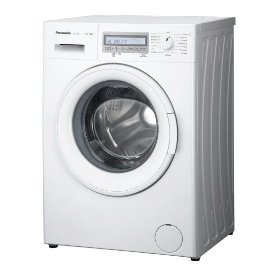
Drum Type Washing Machine
Model No.
Model No.
Model No.
Model No.
Model No.
Model No.
Product Color : White
Destination
PAGE
© Panasonic Corporation 2015 Unauthorized copy-
ing and distribution is a violation of law.
Order No. VES1504005CE
NA-127VC6WFR
NA-127VC6WES
NA-127VC6WTA
NA-127VC6WPL
NA-127VC6WGN
NA-127VC6WNR
: France, Spain, Italy, Poland, Estonia, Lat-
via, Lithuania, Holland, Belgium, Czech,
Hungary, Romania, Slovakia, Croatia,
Serbia, Slovenia, Bosnia-Herzegovina,
Sweden, Norway, Finland, Denmark
PAGE
Advertisement
Table of Contents

Related Manuals for Panasonic NA-127VC6WFR


Summary of Contents for Panasonic NA-127VC6WFR
-
Page 1: Table Of Contents
9 Torque Values ----------------------------------------------------14 10 Disassembly and Assembly Instructions ---------------15 11 Component Specifications -----------------------------------25 12 Wiring Connection Diagram ---------------------------------32 13 Exploded View and Replacement Parts List -----------34 © Panasonic Corporation 2015 Unauthorized copy- ing and distribution is a violation of law. -
Page 3: Specifications
2. Specifications 2.1. Product Specifications Model NA-127VC6 Product Type Front Loader Capacity 7 kg Max Spin Speed 1200 rpm Drum Volume 50 lt Energy Label Rating Energy Consumption 195 kWh / annum Water Consumption 10346 L / annum Wash 58 dBA Noise Level Spin 74 dBA... - Page 4 2.3. Dimension in millimetres NA-127VC6...
-
Page 5: Location Of Controls And Components
3. Location of Controls and Components... -
Page 6: Installation Instructions
4. Installation Instructions Moving and Installing 4.1. 4.1.1. Removal of Transportation Screw 4.1.2. Foot Adjustment 1. Transportation screws, which are located at the back side of 1. Do not install machine on rugs or similar surfaces. the machine, must be removed before running the machine. 2. - Page 7 4.1.4. Water Supply Connection 1. Washing machine is supplied with a single (cold) water inlet. 2. To prevent leakage from the connection joints, a rubber washer is included in the hose packing. Fit this washer at the end of water inlet hose on the tap side. 3.
-
Page 8: Operating Instructions
5. Operating Instructions 5.1. LCD Screen, Function Buttons & Knobs Program selector 16 programs including off position Switch 1, Start / Pause Switch 2, Temperature Selection Switch 3, Spin Speed Selection Switch 4, Delay Timer Selection Switch 5, Extra Rinse Option Switch 6, Easy Ironing Option Switch 7, Eco/Speed Mode Option 7 Segment LCD for Temperature Display... - Page 9 5.2. Program Details...
-
Page 10: Test Mode
5.3. Child Lock Activation The Child Lock Symbol on appears on the LCD display as Child Press SW7 for 5 seconds. Lock is active. Deactivation Press SW7 for 5 seconds. The Child Lock Symbol will disappear on LCD displayupon deactivation. 6. - Page 11 AUTOTEST Time in seconds (to be adjusted) Entering autotest Changing power to 220 50Hz Main Voltage 50 Hz Door Lock Powered (Depends on door lock) Motor Ramp to max spin (max. is 15 sec.) Time until motor is stopped (Depends on the motor stop time) Motor Preferred Run (Direction to Right) Motor Inverse Run (Direction to Left) EV1 (flowrate dependent of washer)
-
Page 12: Service Mode
7. Service Mode 7.1. Service Autotest 1. Set PR to program 3 (Colours) and press SW2 (T°C) 2. While pressing the SW2, change PR position from third to second, and release the SW2 button. 3. Bring PR to desired test step (1 ,2nd or 3 program position) as soon as “SAU”... -
Page 13: Troubleshooting Guide
7.2. Failure Codes Indication For User Indication For Service Error Indication Error Number Yes/No Yes/No Door is not locked Door is unlocked during programme Lack of water Pump failure Overflow NTC or Heater Failure Motor Failure - 1 (Tachometer open-short circuit or motor connector is disconnected) Motor Failure - 2 (triac short circuit) Electronic Pressure Sensor... -
Page 14: Torque Values
FAILURE PROBABLE CAUSE METHODS OF ELIMINATION Press the start/pause button. In order to stop the foam, dilute one table-spoon of softener in Too much detergent has been half liter of water and pour it in the detergent Excessive foam in used. -
Page 15: Disassembly And Assembly Instructions
10. Disassembly and Assembly Instructions 10.1. Top Plate Remove two screws that fix the top-plate at the back. Push the top-plate back and pull it up. 10.2. Door Remove two screws that fix the door. (by using T25 tool) Pull the door up. Remove screws that fix the door group. - Page 16 Remove the door handle. Remove the door handle pin. 10.3. Spring Wire First remove the spring wire fixing the tub bellows seal by using the small size screw driver. Pull the tub bellows Remove the tub bellows seal-body fixing spring. seal.
- Page 17 Pull the control panel out 10.6. Electronic Card & Fuse Release the socket fixing plastic by depressing the taps Depress the taps fixing the card by using a screwdriver with the help of a screwdriver Remove the card out off panel Remove the sockets on the card.
- Page 18 Remove the card from its housing and unplug its Remove the LCD screen by depressing the taps by using connector. a screwdriver. 10.7. Front Panel Remove the screw fixing the front panel at the bottom Remove two screws fixing the door lock Remove the tub bellows seal.
- Page 19 10.8. Support Bracket Remove two clips fixing detergent drawer housing to upper support bracket 10.9. Detergent Drawer Housing Remove the tub bellow hose by releasing the holder Unplug connectors from feed valve extensions of bellow hose Slightly turn the feed valve counter-clockwise to remove Remove the detergent drawer housing assembly 10.10.
- Page 20 Pull the power cable group up Remove EMI filter 10.11. Electronic Pressure Switch (EPS) Unplug EPS connector Pull EPS up 10.12. Door Lock Remove clamp from EPS hose Unplug door lock connector 10.13. Drain Pump Remove clamp holding drain hose by using a plier Remove clamp fixing tub outlet hose...
- Page 21 Unplug drain pump connector Remove screws holding drain pump 10.14. Front Counterweight Remove three screws on the front counterweight. Gently pull counterweight out (Wrench size 13 mm) 10.15. Heater Unplug heater connectors Remove nut (8 mm) fixing the heater Pull heater out gently holding both sides.
- Page 22 10.16. Tub Bellow Seal Hold the tub bellows seal and gasket-body fixing spring Remove the tub gasket clip by using small screwdriver together, and pull them out. 10.17. Transport Screw Remove four transport screws Hold the transport screw and pull it out. 10.18.
- Page 23 10.19. Washing Group Unplug motor connectors Cut all the cable ties which fix cable group Remove the screws fixing hanger bracket Remove the washing group carrying it out through front side 10.20. Shock Absorber Pin 10.21. Driven Pulley Remove shock absorber pins squeezing the ratchet by a Remove the belt rotating the driven pulley pliers 10.22.
- Page 24 10.23. Motor Remove two screws holding motor by using box wrench Pull motor up 10.24. Tub Remove tub inlet bellow hose loosening the clamp Remove screw holding EPS reservoir squeezing it by using a pliers Remove tub outlet bellowed hose loosening screwed- Remove 19 screws around tub using box wrench size 8 clamp Remove front tub...
-
Page 25: Component Specifications
Component Specifications 11.1. Drain Pump Drain pump is both a mechanical and electrical component which is used to drain water inside the washing machine. It has an synchronous motor inside. For better performance maintenance, pump filter should be cleaned regularly. Drain pump Technical features Nominal voltage... - Page 26 11.2. Heater Heating element (Resistance) is a component which is designed to regulate temperature of water inside the drum. It three connections: Phase, neutral ground connections. Resistance Technical features Heater type Tubular heating element Nominal power 2000 W (±5%) with NTC – sensor Resistance 26.4 ±5% Ω...
- Page 27 11.3. NTC Component which sends signals to PCB about the water temperature inside the tub. The Resistance (Ohm) value of the NTC decreases as the temperature increases. Technical features R min R max R min R max (°C) (kΩ) (kΩ) (°C) (kΩ) (kΩ)
- Page 28 11.4. Valve Valve is an electrical and mechanical component which is designed to take water from the network system into the washing machine. It is operated by PCB card. Valve Technical features Nominal voltage 220-240 V Rated flow 7 L/min (±15 %) Nominal power 8 VA Operating water pressure...
- Page 29 11.5. Electronic Pressure Sensor (EPS) Electromagnetic field occurs due to movement of pressurized membrane. The spring moves vertically by nucleus due to electromagnetic field. The water level is regulated according to the frequency changes of the spring by electronic card. Testing component Push the door lock slider with screwdriver Select the 1st program and start the machine...
- Page 30 11.6. Motor The washing machine has an asynchronous motor. It is controlled by the PCB. It is essential to check the motor for correct diagnosis and quick servicing. In the below picture, socket points on the motor is shown to measure with multimeter.
-
Page 31: Wiring Connection Diagram
11.7. Door Lock Door lock is activated at the beginning of the program in order to prevent the door from opening. Locking is generated by supplying power to PTC-bimetal, after max 6sec (220V), the bimetal will be warm and ready to close the contacts.