
Related Manuals for Bosch Rexroth PSI 6 Series


Summary of Contents for Bosch Rexroth PSI 6 Series
- Page 1 Rexroth PSI 6xxx Schweißsteuerung mit Mittelfrequenz-Umrichter Weld Timer with Medium-Frequency Inverter Betriebsanleitung | Operating Instructions Edition 12 1070080028...
- Page 2 This information does not release the user from per forming his own assessments and verifications. Our products are subject to natural wear and aging. © This manual is the exclusive property of Bosch Rexroth AG, Germany also in the case of intellec tual property right applications.
-
Page 3: Table Of Contents
1070080028 / 12 PSI 6xxx Bosch Rexroth AG 3 / 460 Inhalt Inhalt Zu dieser Dokumentation ....Gültigkeit der Dokumentation ...... - Page 4 4 / 460 Bosch Rexroth AG PSI 6xxx | 1070080028 / 12 Inhalt Produktbeschreibung ........
- Page 5 1070080028 / 12 PSI 6xxx Bosch Rexroth AG 5 / 460 Inhalt Produkt elektrisch anschließen ......
- Page 6 6 / 460 Bosch Rexroth AG PSI 6xxx | 1070080028 / 12 Inhalt Fehlersuche und Fehlerbehebung ... . . Technische Daten ......
-
Page 7: Zu Dieser Dokumentation
1070080028 / 12 PSI 6xxx Bosch Rexroth AG 7 / 460 Zu dieser Dokumentation Zu dieser Dokumentation Dieses Kapitel enthält Informationen, die zur Nutzung der Dokumenta tion bedeutsam sind. " Informieren Sie sich über das Produkt, bevor Sie damit arbeiten! Gültigkeit der Dokumentation... -
Page 8: Darstellung Von Informationen
8 / 460 Bosch Rexroth AG PSI 6xxx | 1070080028 / 12 Zu dieser Dokumentation Titel Dok.-Nr. Dokumentart D PSG xxxx: MF-Schweißtransfor 1070087062 Betriebsanleitung matoren D Rexroth PSG xxx R911342242 Sicherheits- und MF-Schweißtransformatoren Gebrauchshin Sicherheits- und Gebrauchshin weise weise BOS 6000 Meldungen... - Page 9 1070080028 / 12 PSI 6xxx Bosch Rexroth AG 9 / 460 Zu dieser Dokumentation Warnzeichen + SIGNALWORT Art und Quelle der Gefahr! Folgen bei Nichtbeachtung! " Maßnahme zur Gefahrenabwehr. " Weitere Maßnahme(n) zur Gefahrenabwehr. Integrierte Sicherheitshinweise können in das Format der Umge...
- Page 10 10 / 460 Bosch Rexroth AG PSI 6xxx | 1070080028 / 12 Zu dieser Dokumentation Zur Klassifizierung sind Sicherheitshinweise nach Gefahrenstufen Gefahrenstufen? (Gefahrenklassen) unterteilt. Das Signalwort repräsentiert die Gefah renstufe. Tab. 3: Gefahrenklassen nach ANSI Z535.6 Signalwort Bedeutung GEFAHR Gefährliche Situation, in der Tod oder schwere Körperver...
-
Page 11: Symbole
1070080028 / 12 PSI 6xxx Bosch Rexroth AG 11 / 460 Zu dieser Dokumentation 1.3.2 Symbole Die folgende Symbolik wird verwendet, um Textpassagen besonders zu kennzeichnen. Tab. 5: Verwendete Symbolik Symbol Bedeutung Kennzeichnung für einen Tipp oder eine Information. Hilft, das Produkt optimal zu nutzen, zu betreiben, oder Zusammenhänge besser zu verstehen. - Page 12 12 / 460 Bosch Rexroth AG PSI 6xxx | 1070080028 / 12 Zu dieser Dokumentation Notizen | Notes:...
-
Page 13: Sicherheitshinweise
1070080028 / 12 PSI 6xxx Bosch Rexroth AG 13 / 460 Sicherheitshinweise Sicherheitshinweise Dieses Kapitel enthält wichtige Informationen zum sicheren Umgang mit dem beschriebenen Produkt. Zu diesem Kapitel Das beschriebene Produkt wurde unter Beachtung der EG-Normen entwickelt, gefertigt, geprüft und dokumentiert. -
Page 14: Qualifikation Des Personals
(z.B. Luftfeuchtigkeit), • Elektrischer Anschluss entspricht nicht der Dokumentation. Für Schäden bei nicht bestimmungsgemäßer Verwendung übernimmt die Bosch Rexroth AG keine Haftung. Die Risiken bei nicht bestim mungsgemäßer Verwendung trägt allein der Betreiber/Benutzer. Qualifikation des Personals Diese Dokumentation wendet sich an speziell ausgebildetes Fachper... - Page 15 1070080028 / 12 PSI 6xxx Bosch Rexroth AG 15 / 460 Sicherheitshinweise Projektierung, Programmierung, Start und Bedienung sowie das " Verändern von Programmparametern darf nur durch entsprechend geschultes Fachpersonal erfolgen! Dieses Personal muss in der Lage sein, mögliche Gefahren zu erkennen, die durch Program...
-
Page 16: Allgemeine Sicherheitshinweise
16 / 460 Bosch Rexroth AG PSI 6xxx | 1070080028 / 12 Sicherheitshinweise Allgemeine Sicherheitshinweise Beachten Sie die gültigen Vorschriften zur Unfallverhütung und zum " Umweltschutz. " Beachten Sie die Sicherheitsvorschriften und -bestimmungen des Landes, in dem das Produkt eingesetzt/angewendet wird. -
Page 17: Produkt- Und Technologieabhängige Sicherheitshinweise
1070080028 / 12 PSI 6xxx Bosch Rexroth AG 17 / 460 Sicherheitshinweise Produkt- und technologieabhängige Sicherheitshinweise In diesem Kapitel finden Sie grundsätzliche Hinweise und Anwei sungen, die für Ihre Sicherheit beim Handling mit dem Produkt und der Technologie im Umfeld des Produktes wichtig sind. -
Page 18: Einbau Und Montage
18 / 460 Bosch Rexroth AG PSI 6xxx | 1070080028 / 12 Sicherheitshinweise 2.6.3 Einbau und Montage WARNUNG Gefährliche elektrische Spannung Herz-Rhythmusstörung, Verbrennung, Schock möglich! Stellen Sie sicher, dass alle Anlagenteile, an denen während " Montagevorgängen gearbeitet wird, spannungsfrei und gegen willkürliches/unbeabsichtigtes Wiedereinschalten ausreichend... - Page 19 1070080028 / 12 PSI 6xxx Bosch Rexroth AG 19 / 460 Sicherheitshinweise VORSICHT Unzureichende Befestigung Reduzierung der Personen-/Anlagensicherheit, Funktionsstö rungen möglich! " Stellen Sie sicher, dass Einbauort und Befestigung der Komponenten auf deren Gewicht ausgelegt sind! Berücksichtigen Sie hierbei auch dynamische Kräfte, die ggf. auf das Produkt einwirken.
-
Page 20: Elektrischer Anschluss
20 / 460 Bosch Rexroth AG PSI 6xxx | 1070080028 / 12 Sicherheitshinweise 2.6.4 Elektrischer Anschluss WARNUNG Gefährliche elektrische Spannung Herz-Rhythmusstörung, Verbrennung, Schock möglich! Der elektrische Anschluss darf nur von einer Elektrofachkraft un " ter Beachtung der gültigen Sicherheitsbestimmungen, der Netz... - Page 21 1070080028 / 12 PSI 6xxx Bosch Rexroth AG 21 / 460 Sicherheitshinweise WARNUNG Nicht oder falsch ausgewertete Fehlermeldungen Reduzierung der Personen-/Anlagensicherheit, Funktionsstö rungen möglich! " Viele Meldungen können in der SST entsprechend Ihren An forderungen als ”Warnung” (keine Blockade) oder ”Fehler” (mit Blockade) frei konfiguriert werden.
-
Page 22: Betrieb Des Produktes
22 / 460 Bosch Rexroth AG PSI 6xxx | 1070080028 / 12 Sicherheitshinweise WARNUNG Fehlerhafter Anschluss von Anschlusskabeln Reduzierung der Personen-/Anlagensicherheit, Funktionsstö rungen/-einschränkungen möglich! " Dimensionieren Sie alle Leiterquerschnitte entsprechend der An schlussleistung. " Stellen Sie sicher, dass sich keine Anschlusskabel ungewollt lö... - Page 23 1070080028 / 12 PSI 6xxx Bosch Rexroth AG 23 / 460 Sicherheitshinweise WARNUNG Hohe dynamische Kräfte und sehr schnelle Bewegungsabläufe Schlag-, Quetsch-, Einzugs- und Verbrennungsgefahr! Rechnen Sie stets mit Bewegungsabläufen, die durch auftre " tende Fehler an der Anlage hervorgerufen werden können und verhalten Sie sich entsprechend umsichtig und besonnen.
-
Page 24: Nachrüstungen Und Veränderungen Durch Den Betreiber
24 / 460 Bosch Rexroth AG PSI 6xxx | 1070080028 / 12 Sicherheitshinweise VORSICHT Schweißspritzer, heiße Oberflächen, scharfe Blechkanten Verbrennungen, Augenverletzungen möglich! Tragen Sie Schutzhandschuhe, um sich vor Verletzungen an " scharfen Blechkanten oder vor Verbrennungen am Schweißgut zu schützen! "... -
Page 25: Wartung Und Reparatur
1070080028 / 12 PSI 6xxx Bosch Rexroth AG 25 / 460 Sicherheitshinweise 2.6.7 Wartung und Reparatur WARNUNG Gefährliche elektrische Spannung Herz-Rhythmusstörung, Verbrennung, Schock möglich! " Wartungsarbeiten sind - wenn nicht anders beschrieben - grund sätzlich nur bei ausgeschalteter und ausreichend gesicherter Anlage durchzuführen! -
Page 26: Konformitätserklärung / Ce-Kennzeichnung
26 / 460 Bosch Rexroth AG PSI 6xxx | 1070080028 / 12 Sicherheitshinweise VORSICHT Unsachgemäße Handhabung von Lithium-Batterien Verätzung, Explosion möglich! Öffnen Sie Lithium-Batterien nicht gewaltsam. " " Laden Sie eine verbrauchte Lithium-Batterie nicht wieder auf. Erhitzen Sie Lithium-Batterien nicht über 100 Grad Celsius. -
Page 27: Pflichten Des Betreibers
1070080028 / 12 PSI 6xxx Bosch Rexroth AG 27 / 460 Sicherheitshinweise Pflichten des Betreibers Der Betreiber ist verantwortlich für die Anlage. Deswegen muss er • die bestimmungsgemäße Verwendung der Anlage sicherstellen, • das Betriebspersonal regelmäßig unterweisen, • bestehende Gefahren für alle Personen unübersehbar und eindeu... - Page 28 28 / 460 Bosch Rexroth AG PSI 6xxx | 1070080028 / 12 Sicherheitshinweise Notizen | Notes:...
-
Page 29: Allgemeine Hinweise Zu Sachschäden Und
1070080028 / 12 PSI 6xxx Bosch Rexroth AG 29 / 460 Allgemeine Hinweise zu Sachschäden und Produktschäden Allgemeine Hinweise zu Sachschäden und Produktschäden Vorliegendes Kapitel enthält Hinweise, die zum Schutz vor Sach- und Produktschäden wichtig sind. Transport und Lagerung HINWEIS Unsachgemäßes Handling von Geräten mit Wasserkühlung... -
Page 30: Einbau Und Montage
30 / 460 Bosch Rexroth AG PSI 6xxx | 1070080028 / 12 Allgemeine Hinweise zu Sachschäden und Produktschäden Einbau und Montage HINWEIS Unsachgemäßes Handling von Geräten mit Wasserkühlung Leck im Kühlkreislauf möglich! Stellen Sie sicher, dass Wasseranschlüsse und Schlauch "... - Page 31 1070080028 / 12 PSI 6xxx Bosch Rexroth AG 31 / 460 Allgemeine Hinweise zu Sachschäden und Produktschäden HINWEIS Überhitzung oder Schwitzwasser durch unzureichende Kühlung Temporäres Stocken des Schweißablaufes, Verminderung der Produktlebensdauer, Zerstörung des Gerätes, Schäden an der elektrischen Ausrüstung, unvorhersehbare Anlagenreaktionen möglich!
-
Page 32: Elektrischer Anschluss
32 / 460 Bosch Rexroth AG PSI 6xxx | 1070080028 / 12 Allgemeine Hinweise zu Sachschäden und Produktschäden Elektrischer Anschluss HINWEIS Falsche Spannungsversorgung Schäden an der elektrischen Ausrüstung möglich! " Prüfen Sie, ob die Netzspannung mit der auf dem Typenschild des Produkts angegebenen Nennspannung übereinstimmt! - Page 33 1070080028 / 12 PSI 6xxx Bosch Rexroth AG 33 / 460 Allgemeine Hinweise zu Sachschäden und Produktschäden HINWEIS Elektrostatische Aufladung Schäden an der elektrischen Ausrüstung möglich! " Halten Sie beim Umgang mit Baugruppen und Bauelementen alle Vorkehrungen zum ESDSchutz ein und vermeiden Sie elektrostatische Entladungen.
-
Page 34: Betrieb
34 / 460 Bosch Rexroth AG PSI 6xxx | 1070080028 / 12 Allgemeine Hinweise zu Sachschäden und Produktschäden Betrieb HINWEIS HF-Störstrahlung Störungen anderer Geräte in der Umgebung möglich! Stellen Sie sicher, dass durch den Betrieb des Produktes andere " Geräte nicht in ihrer Funktion beeinträchtigt werden können. -
Page 35: Wartung Und Reparatur
1070080028 / 12 PSI 6xxx Bosch Rexroth AG 35 / 460 Allgemeine Hinweise zu Sachschäden und Produktschäden Wartung und Reparatur HINWEIS Ziehen oder Stecken von Baugruppen oder Steckverbindungen unter Spannung Schäden an der elektrischen Ausrüstung, unvorhersehbare An lagenreaktionen möglich! Wenn nicht anders beschrieben, Steckverbindungen nie unter "... - Page 36 36 / 460 Bosch Rexroth AG PSI 6xxx | 1070080028 / 12 Allgemeine Hinweise zu Sachschäden und Produktschäden Notizen | Notes:...
-
Page 37: Lieferumfang
1070080028 / 12 PSI 6xxx Bosch Rexroth AG 37 / 460 Lieferumfang Lieferumfang Der Lieferumfang ist abhängig vom Auftrag. Deswegen ist an dieser Stelle keine global gültige Aussage über den Umfang Ihrer speziellen Lieferung möglich. " Kontrollieren Sie den Lieferumfang anhand des Lieferscheins. - Page 38 38 / 460 Bosch Rexroth AG PSI 6xxx | 1070080028 / 12 Lieferumfang Notizen | Notes:...
-
Page 39: Zu Diesem Produkt
1070080028 / 12 PSI 6xxx Bosch Rexroth AG 39 / 460 Zu diesem Produkt Zu diesem Produkt Die Geräte der Baureihe PSI 6xxx sind Schweißeinrichtungen der Klasse A und enthalten standardmäßig • Schweißsteuerung (SST) und • Mittelfrequenz-Leistungsteil (MF-Umrichter). Aufgaben des MF-Umrichters: •... - Page 40 40 / 460 Bosch Rexroth AG PSI 6xxx | 1070080028 / 12 Zu diesem Produkt • Unterschiedlichste verfügbare E/A-Schnittstellen zur Kommunika tion mit SPS, Roboter oder zur Anbindung eines Maschinenbedien feldes • Optional verfügbare Feldbusschnittstellen zur Kommunikation mit einer übergeordneten Leitebene •...
-
Page 41: Leistungsbeschreibung
1070080028 / 12 PSI 6xxx Bosch Rexroth AG 41 / 460 Zu diesem Produkt Leistungsbeschreibung • Oberfläche für Bedienung, Programmierung und Diagnose: - komplett per grafischer Bedienoberfläche BOS; - Systemvoraussetzungen: lauffähig auf PCs mit Betriebssystem ab Windows 7 mit Service Pack 1 (32 Bit, 64 Bit) Windows 8 bzw. - Page 42 42 / 460 Bosch Rexroth AG PSI 6xxx | 1070080028 / 12 Zu diesem Produkt - KSR (Konstant-Strom-Regelung) - UIR (Adaptiver Regler; optional) Die Regelungsbetriebsarten PHA und KSR sind für jede Stromzeit separat einstellbar (Mix-Betrieb). UIR nur in 2.STZ. • Stromüberwachung: - Referenzströme sind unabhängig von den Regelungssollwerten...
- Page 43 1070080028 / 12 PSI 6xxx Bosch Rexroth AG 43 / 460 Zu diesem Produkt • Leistungskorrektur: - programmspezifische Vorgabe - elektrodenspezifische Vorgabe • Gesamt-Übersicht über die Schweißlinie per Anlagenbild • SST-globale Anzeige der - Ablaufsperre (P) - Zündung intern ein (P) - Zeitüberwachung...
-
Page 44: Produktbeschreibung
44 / 460 Bosch Rexroth AG PSI 6xxx | 1070080028 / 12 Zu diesem Produkt Produktbeschreibung Steuerung und Leistungsteil sind in einem gemeinsamen Gehäuse montiert. PSI 6500.XXX PSI 6500.XXX PSI 6500.XXX PSI 6500.XXX PSI 6500.XXX PSI 6500.XXX PSI 6500.XXX PSI 6200.XXX PSI 6200.XXX... -
Page 45: Programmierung Und Bedienung
1070080028 / 12 PSI 6xxx Bosch Rexroth AG 45 / 460 Zu diesem Produkt 5.2.1 Programmierung und Bedienung Alle erforderlichen Parameter werden immer im steuerungsinternen batteriegepufferten RAM gehalten. Die Bedienung, Programmierung und Diagnose erfolgt per ange koppeltem PC. Zur Ankopplung des PC stehen zur Verfügung: •... -
Page 46: Funktionsprinzip Des Mittelfrequenzschweißens
46 / 460 Bosch Rexroth AG PSI 6xxx | 1070080028 / 12 Zu diesem Produkt 5.2.2 Funktionsprinzip des Mittelfrequenzschweißens PSI 6xxx PSI 6xxx 1000 Transformator- Schweiß- Steuerteil MF-Umrichter Gleichrichter vorrichtung Abb. 2: Übersichts-Blockschaltbild: PSI 6000 mit Trafo Der im PSI integrierte MF-Umrichter steuert den Schweißtransformator mit einer bipolaren, rechteckförmigen Spannung mit einer Frequenz... - Page 47 1070080028 / 12 PSI 6xxx Bosch Rexroth AG 47 / 460 Zu diesem Produkt Ausgangsspannung des Mit resultierender telfrequenz-Umrichters Schweißstrom 1 ms Abb. 4: Sekundärseitige Gleichrichtung durch den PSG-Transformator Primärspannung kleine Pulsbreite PRIM f = 1 kHz resultierender Sekundärstrom resultierende Leistung Primärspannung...
-
Page 48: Aufbau
48 / 460 Bosch Rexroth AG PSI 6xxx | 1070080028 / 12 Zu diesem Produkt 5.2.3 Aufbau Das Leistungsteil ist im linksseitigen, das Steuerungsmodul im rechts seitigen Gehäuseteil fest montiert. Am Leistungsteil befinden sich immer die Anschlüsse für • Netzversorgung, •... - Page 49 1070080028 / 12 PSI 6xxx Bosch Rexroth AG 49 / 460 Zu diesem Produkt Informationen zur Montage und zum Anschluss siehe Kap. 7 ab Seite 115. Für die Beschreibung typabhängiger Funktionen/Anschlüsse des Steuerungsmoduls sind zusätzliche Dokumente verfügbar (siehe Seite 7).
-
Page 50: Teil-Frontansicht Psi 6X00.Xxx
50 / 460 Bosch Rexroth AG PSI 6xxx | 1070080028 / 12 Zu diesem Produkt 5.2.3.1 Teil-Frontansicht PSI 6x00.xxx LED LOGIK; grün. Leuchtet, wenn 24 V (Logik-Versorgungsspannung) ansteht. LED ZWISCHENKREIS; rot (nur funktionsfähig, wenn LED LOGIK grün leuchtet). Leuchtet, wenn Zwischenkreisspannung aufgebaut ist LED BEREIT;... - Page 51 1070080028 / 12 PSI 6xxx Bosch Rexroth AG 51 / 460 Zu diesem Produkt Die LEDs können den Status der SST nur dann melden, wenn die Logik-Versorgungsspannung ansteht! HINWEIS Willkürliches Drücken des Boot-Tasters Negative Auswirkungen auf die laufende Produktion möglich! Boot-Taster nie während laufender Produktion betätigen.
-
Page 52: Teil-Frontansicht Psi 6Xcx.xxx
52 / 460 Bosch Rexroth AG PSI 6xxx | 1070080028 / 12 Zu diesem Produkt 5.2.3.2 Teil-Frontansicht PSI 6xCx.xxx 24 V -Ausgang zur E/A-Modul-Versorgung (siehe Seite 141). 24 V -Ausgang der internen Spannungsquelle (siehe Seite 140). 24 V -Eingang zur Logik-Spannungsversorgung (siehe Seite 139). - Page 53 1070080028 / 12 PSI 6xxx Bosch Rexroth AG 53 / 460 Zu diesem Produkt LEDs und Diagnosemodul können den Status der SST nur dann melden, wenn die Logik-Versorgungsspannung ansteht!
-
Page 54: Module
54 / 460 Bosch Rexroth AG PSI 6xxx | 1070080028 / 12 Zu diesem Produkt 5.2.4 Module 5.2.4.1 AnyBus-Modul ”ProfiNet IO“ Merkmale: • Geeignet für PSI 6xCx.xxx (Steckplatz X7E1) • ProfiNet (RT-Klassifikation, Konformitätsklasse B) • Fast-Ethernet (100 MBit/s), Full-Duplex-Betrieb • Als 1- oder 2-Port-Variante verfügbar. 2-Port-Variante mit In... - Page 55 1070080028 / 12 PSI 6xxx Bosch Rexroth AG 55 / 460 Zu diesem Produkt Informationen zum Einbau siehe Kap. 13.2.1 ab Seite 190. Zur Ethernet-Konfiguration verwenden Sie die Software ”Anybus IP config” (Installationsdatei ist im BOS-Softwarepaket enthalten; siehe BOS-Datenträger: Verzeichnispfad „Tools/Anybus“).
-
Page 56: Anybus-Modul "Cc Ethernet 100 Mbit
56 / 460 Bosch Rexroth AG PSI 6xxx | 1070080028 / 12 Zu diesem Produkt 5.2.4.2 AnyBus-Modul ”CC Ethernet 100 Mbit” Merkmale: • Geeignet für PSI 6xCx.xxx (Steckplatz X7E1) • Fast-Ethernet (100 MBit/s), Full-Duplex-Betrieb • Als 1- oder 2-Port-Variante verfügbar. 2-Port-Variante mit In... -
Page 57: Baugruppe "Cc Ethernet 100 Mbit
1070080028 / 12 PSI 6xxx Bosch Rexroth AG 57 / 460 Zu diesem Produkt 5.2.4.3 Baugruppe ”CC Ethernet 100 Mbit“ Merkmale: • Geeignet für PSI 6xxx.xxx (Steckplatz für Feldbus-Modul) • Ethernet-Einschub-Baugruppe auf der Basis eines AnyBus-Moduls. • Fast-Ethernet (100 MBit/s), Full-Duplex-Betrieb •... -
Page 58: Baugruppe "Cc Profinet
58 / 460 Bosch Rexroth AG PSI 6xxx | 1070080028 / 12 Zu diesem Produkt 5.2.4.4 Baugruppe ”CC ProfiNet“ Merkmale: • Geeignet für PSI 6xxx.xxx (Steckplatz für Feldbus-Modul) • ProfiNet-Einschub-Baugruppe auf der Basis eines AnyBus-Moduls. • ProfiNet (RT-Klassifikation, Konformitätsklasse B) •... -
Page 59: Baugruppe „Profinet-Irt, 2-Port (M40-Modul)
1070080028 / 12 PSI 6xxx Bosch Rexroth AG 59 / 460 Zu diesem Produkt 5.2.4.5 Baugruppe „Profinet-IRT, 2-Port (M40-Modul)“ Merkmale: • Materialnummer 1070094170 • Geeignet für PSI 6xxx.xxx (Steckplatz für Feldbus-Modul) • Wie CC Profinet nur als 2 Port Variante mit ProfiNet IRT •... -
Page 60: Baugruppe "Lwl Profinet
60 / 460 Bosch Rexroth AG PSI 6xxx | 1070080028 / 12 Zu diesem Produkt 5.2.4.6 Baugruppe ”LWL ProfiNet“ Merkmale: • Geeignet für PSI 6xxx.xxx (Steckplatz für Feldbus-Modul) • LWL ProfiNet-Einschub-Baugruppe • ProfiNet-Anschaltung gemäß IRT-Klassifikation, Konformitäts klasse C • Integrierter WEB-Server •... -
Page 61: Baugruppe „Profinet-Irt, Lwl (M40-Modul)
1070080028 / 12 PSI 6xxx Bosch Rexroth AG 61 / 460 Zu diesem Produkt 5.2.4.7 Baugruppe „Profinet-IRT, LWL (M40-Modul)“ Merkmale: • Materialnummer 1070093995 • Geeignet für PSI 6xxx.xxx (Steckplatz für Feldbus-Modul) • Wie LWL Profinet mit Lichtwellenleiter-Anschlüssen nur mit ProfiNet IRT (LWL) •... -
Page 62: Diagnosemodul
62 / 460 Bosch Rexroth AG PSI 6xxx | 1070080028 / 12 Zu diesem Produkt 5.2.4.8 Diagnosemodul Nur in Verbindung mit PSI 6xCx.xxx. 8-stelliges Display Enter Abb. 16: Frontansicht Diagnosemodul Funktionen: • Anzeigen von SST-Zustand, -Typ, -Zeit, Ethernet-Konfiguration • Fehler/Warnungen quittieren •... - Page 63 1070080028 / 12 PSI 6xxx Bosch Rexroth AG 63 / 460 Zu diesem Produkt Hardwarefehler lassen sich nicht quittieren. Selbstquittierende Fehler quittiert das System bei Wegfall der Fehlerursache automatisch (z.B. Netzspannung Aus/Ein). Auch bei anstehenden Fehlern lassen sich am Display weitere In...
- Page 64 64 / 460 Bosch Rexroth AG PSI 6xxx | 1070080028 / 12 Zu diesem Produkt Hauptmenüpunkt ETHERNET: Anzeige Ethernet-Konfiguration für AnyBus-Modul (ETHERN.1) oder - sofern gesteckt - für die Baugruppe ”CC Ethernet 100 Mbit“ (ETHERN.2). Folgendes Diagramm gibt Ihnen eine Strukturübersicht: zum / vom Hauptmenü...
- Page 65 1070080028 / 12 PSI 6xxx Bosch Rexroth AG 65 / 460 Zu diesem Produkt Fehler quittieren Drücken Sie Taste ”Enter”. Das Display zeigt ”Err Quit” an. Drücken Sie Taste ”Esc” um das Quittieren abzubrechen oder Taste ”Enter” um zu quittieren.
-
Page 66: E/A-Modul "E/A Disk R2Ed" Und "E/A Disk R4Ed
66 / 460 Bosch Rexroth AG PSI 6xxx | 1070080028 / 12 Zu diesem Produkt 5.2.4.9 E/A-Modul ”E/A DISK R2ED” und ”E/A DISK R4ED“ Merkmale: • 26 diskrete Eingänge (24 V • 1 Ausgang als geschaltetes Relais (1 x EIN) •... - Page 67 1070080028 / 12 PSI 6xxx Bosch Rexroth AG 67 / 460 Zu diesem Produkt Diskrete Signal-Aus- und -Eingänge Anschluss: E/A DISK R2ED: X11:8pol.; X12:14pol.; X13:12pol.; X14:16pol. E/A DISK R4ED: X21:8pol.; X22:14pol.; X23:12pol.; X24:16pol. STKK, Raster 3,5 mm, max. 1,5 mm Gegenstecker sind im Lieferumfang enthalten.
- Page 68 68 / 460 Bosch Rexroth AG PSI 6xxx | 1070080028 / 12 Zu diesem Produkt Signal-Eingänge E0 bis E13 (24 V ), mit Kontroll-LED 2x Spannungsausgang zur Versorgung der ext. Ein gangsschaltungen (intern von X10 abgegriffen) Signal-Eingänge E14 bis E25 (24 V ), mit Kontroll-LED Signal-Ausgänge, mit Kontroll-LED.
-
Page 69: E/A-Modul "E/A Disk
1070080028 / 12 PSI 6xxx Bosch Rexroth AG 69 / 460 Zu diesem Produkt 5.2.4.10 E/A-Modul ”E/A DISK” Merkmale: • 21 diskrete Eingänge (24 V • 13 diskrete Ausgänge (24 V Funktion: • Ankopplung diskreter E/A-Signale. Tab. 10: Technische Daten: E/A-Modul ”E/A DISK“... - Page 70 70 / 460 Bosch Rexroth AG PSI 6xxx | 1070080028 / 12 Zu diesem Produkt Feinsicherung M 1,6 A; zur Absicherung von Ausgang A0 Feinsicherung M 1,6 A; zur Absicherung der Ausgänge A1 bis A12 Signal-Eingänge E0 bis E13 (24 V ), mit Kontroll-LED 2x Spannungsausgang zur Versorgung der ext.
-
Page 71: E/A-Module "E/A Disk 2R" Und "E/A Disk 4R
1070080028 / 12 PSI 6xxx Bosch Rexroth AG 71 / 460 Zu diesem Produkt 5.2.4.11 E/A-Module ”E/A DISK 2R” und ”E/A DISK 4R“ Merkmale: • je 22 diskrete Eingänge (24 V • je 1 Ausgang als geschaltetes Relais (1 x EIN) •... - Page 72 72 / 460 Bosch Rexroth AG PSI 6xxx | 1070080028 / 12 Zu diesem Produkt Diskrete Signal-Aus- und -Eingänge Anschluss: E/A DISK 2R: X11: 18polig; X12: 8polig; X13: 16polig E/A DISK 4R: X21: 18polig; X22: 8polig; X23: 16polig STKK, Raster 3,5 mm, max. 1,5 mm Gegenstecker sind im Lieferumfang enthalten.
- Page 73 1070080028 / 12 PSI 6xxx Bosch Rexroth AG 73 / 460 Zu diesem Produkt Feinsicherung M 1,6 A; zur Absicherung von Ausgang A0 und A13 bis A15 Feinsicherung M 1,6 A; zur Absicherung der Ausgänge A1 bis A10 Signal-Eingänge E0 bis E13 (24 V ), mit Kontroll-LED 2x Spannungsausgang zur Versorgung der ext.
- Page 74 74 / 460 Bosch Rexroth AG PSI 6xxx | 1070080028 / 12 Zu diesem Produkt Notizen | Notes:...
-
Page 75: E/A-Modul "E/A Ibs Opc Mit Lwl" (Interbus-S)
1070080028 / 12 PSI 6xxx Bosch Rexroth AG 75 / 460 Zu diesem Produkt 5.2.4.12 E/A-Modul ”E/A IBS OPC mit LWL” (INTERBUS-S) Nur in Verbindung mit PSI 6x00.xxx. Merkmale: • 8 diskrete Eingänge (24 V • 8 diskrete Ausgänge (24 V •... - Page 76 76 / 460 Bosch Rexroth AG PSI 6xxx | 1070080028 / 12 Zu diesem Produkt Spannungsversorgung Anschluss: X10: 4polig; STKK, Raster 3,5 mm, max. 1,5 mm Gegenstecker ist im Lieferumfang enthalten. Leitungslänge: (von Spannungsquelle bis zum Verbraucher) max. 10 m bei 0,75 mm max.
- Page 77 1070080028 / 12 PSI 6xxx Bosch Rexroth AG 77 / 460 Zu diesem Produkt Diagnosemeldungen der Baugruppe: TR: Transmit/Receive; hier keine Bedeutung. CC: Cable Check; Busverbindung (vom vorherigen IB-S-Teil nehmer kommend) besteht. Erlischt bei Reset am Master. UL: Unit Supply; Leuchtet: Versorgungsspannung steht an (X10).
- Page 78 78 / 460 Bosch Rexroth AG PSI 6xxx | 1070080028 / 12 Zu diesem Produkt Einstellung Baudrate und Sendeleistung " Verändern der Sendeleistung ist ohne Rücksprache mit uns nicht erlaubt. E/A-Modul Frontseite Sendeleistung Baudrate: 500 kB off: 2 MB Manuelle Markierungen mit den Werkseinstellungen der Sendeleistung.
-
Page 79: E/A-Modul "E/A Ibs Fern" (Interbus-S)
1070080028 / 12 PSI 6xxx Bosch Rexroth AG 79 / 460 Zu diesem Produkt 5.2.4.13 E/A-Modul ”E/A IBS FERN” (INTERBUS-S) Merkmale: • 8 diskrete Eingänge (24 V • 8 diskrete Ausgänge (24 V • INTERBUS-S-Anschluss per Kupferkabel Funktion: • Anbindung der Steuerungs-E/A an die übergeordnete SPS oder den Roboter •... - Page 80 80 / 460 Bosch Rexroth AG PSI 6xxx | 1070080028 / 12 Zu diesem Produkt INTERBUS‐S‐Anschluss IN (vom vorherigen IB‐S‐Teilnehmer kommend) - Pinbelegung siehe Seite 81 Diagnosemeldungen der Baugruppe: - US: Unit Supply; Versorgungsspannung steht an - RC: Remotebus Check; Busverbindung (vom vorherigen IB‐S‐Teilnehmer kommend) besteht.
- Page 81 1070080028 / 12 PSI 6xxx Bosch Rexroth AG 81 / 460 Zu diesem Produkt Schweißsteuerung vorheriger X13 (IBS-IN) INTERBUS-S-Teilnehmer /DO1 /DI1 Stecker Schirm großflächig über metallisches Gehäuse der Steckverbindung X12 (IBS-OUT) +5 V /DO2 /DI2 RBST nachfolgender INTERBUS-S-Teilnehmer Buchse Schirm großflächig über metallisches Gehäuse der Steckverbindung...
- Page 82 82 / 460 Bosch Rexroth AG PSI 6xxx | 1070080028 / 12 Zu diesem Produkt Notizen | Notes:...
-
Page 83: E/A-Modul "E/A Ibs X_Fern_8Ea" (Interbus-S)
1070080028 / 12 PSI 6xxx Bosch Rexroth AG 83 / 460 Zu diesem Produkt 5.2.4.14 E/A-Modul ”E/A IBS X_FERN_8EA” (INTERBUS-S) Merkmale: • 8 diskrete Eingänge (24 V • 8 diskrete Ausgänge (24 V • INTERBUS-S-Anschluss per Kupferkabel Funktion: • Anbindung der Steuerungs-E/A an die übergeordnete SPS oder den Roboter •... - Page 84 84 / 460 Bosch Rexroth AG PSI 6xxx | 1070080028 / 12 Zu diesem Produkt INTERBUS‐S‐Anschluss IN (vom vorherigen IB‐S‐Teilnehmer kommend) - Pinbelegung siehe Seite 85 Diagnosemeldungen der Baugruppe: : Unit Supply; Versorgungsspannung steht an - RC: Remotebus Check; Busverbindung (vom vorherigen IB‐S‐Teilnehmer kommend) besteht.
- Page 85 1070080028 / 12 PSI 6xxx Bosch Rexroth AG 85 / 460 Zu diesem Produkt Schweißsteuerung vorheriger X13 (IBS-IN) INTERBUS-S-Teilnehmer /DO1 /DI1 Stecker Schirm großflächig über metallisches Gehäuse der Steckverbindung X12 (IBS-OUT) +5 V /DO2 /DI2 RBST nachfolgender INTERBUS-S-Teilnehmer Buchse Schirm großflächig über metallisches Gehäuse der Steckverbindung...
- Page 86 86 / 460 Bosch Rexroth AG PSI 6xxx | 1070080028 / 12 Zu diesem Produkt Notizen | Notes:...
-
Page 87: E/A-Modul "Dev-Net" (Devicenet)
1070080028 / 12 PSI 6xxx Bosch Rexroth AG 87 / 460 Zu diesem Produkt 5.2.4.15 E/A-Modul ”DEV-NET” (DeviceNet) Merkmale: • 8 diskrete Eingänge (24 V • 8 diskrete Ausgänge (24 V • DeviceNet-Anschluss per Bus-Kupferkabel Funktion: • Anbindung der Steuerungs-E/A an die übergeordnete SPS oder den Roboter •... - Page 88 88 / 460 Bosch Rexroth AG PSI 6xxx | 1070080028 / 12 Zu diesem Produkt - Diagnosemeldungen der Baugruppe (nach DeviceNet‐Spezifikation) - NA: Einstellung der Node-Adresse (Mac ID) - DR: Einstellung der Baudrate (jeweils nach DeviceNet‐Spezifikation) Wertigkeit (dez.) Node-Adresse (0 - 63): DIP-Schalternr.
-
Page 89: E/A-Modul "Comnetm-Dp" (Profibus-Dp)
1070080028 / 12 PSI 6xxx Bosch Rexroth AG 89 / 460 Zu diesem Produkt 5.2.4.16 E/A-Modul ”ComnetM-DP” (PROFIBUS-DP) Merkmale: • 16 diskrete Eingänge (24 V • 16 diskrete Ausgänge (24 V • PROFIBUS-DP-Anschluss per Bus-Kupferkabel Funktion: • Anbindung der Steuerungs-E/A an die übergeordnete SPS oder den Roboter •... - Page 90 90 / 460 Bosch Rexroth AG PSI 6xxx | 1070080028 / 12 Zu diesem Produkt - Diagnosemeldungen der Baugruppe (nach PROFIBUS‐Spezifikation) - Busanschluss. Pinbelegung: Schirm RXD / TXD ‐P CNTR ‐P DGND RXD / TXD ‐N - DP‐ADR: Einstellung der PROFIBUS-DP-Adresse Drehschalter ”*10“: Zehnerstelle (0...9)
-
Page 91: Ui-Regler-Modul (Psq 6000 Xqr)
1070080028 / 12 PSI 6xxx Bosch Rexroth AG 91 / 460 Zu diesem Produkt 5.2.4.17 UI-Regler-Modul (PSQ 6000 XQR) Nur bei entsprechend benötigter Funktion/Ausbaustufe in Ver bindung mit PSI 6x00.xxx erforderlich. Merkmale: • Optionale Einsteckkarte Funktionserweiterung einer PSI 6x00.xxx. Funktionen: •... - Page 92 92 / 460 Bosch Rexroth AG PSI 6xxx | 1070080028 / 12 Zu diesem Produkt Abb. 30: Frontansicht: UI-Regler-Modul PSQ 6000 XQR“ Eingänge zum Anschluss der geschirmten Anzeige CAN-Bus-Kommunikation: Spannungsmessleitungen U1 und U2. grüne LED: Kommunikation ok rote LED: Kommunikation gestört Anzeige Baugruppen-Betriebszustand: RS232-Schnittstelle.
- Page 93 1070080028 / 12 PSI 6xxx Bosch Rexroth AG 93 / 460 Zu diesem Produkt Notizen | Notes:...
-
Page 94: Belastung Und Dimensionierung
94 / 460 Bosch Rexroth AG PSI 6xxx | 1070080028 / 12 Zu diesem Produkt Belastung und Dimensionierung 5.3.1 Grundlegendes Prinzipiell haben Halbleiter, solange sie innerhalb der Spezifikation be trieben werden, eine nahezu unendliche Lebensdauer. Aufgrund thermischer Belastungen wirken aber auf die Halbleiterchips auch mechanische Kräfte, die in Abhängigkeit der Halbleitergröße die... - Page 95 1070080028 / 12 PSI 6xxx Bosch Rexroth AG 95 / 460 Zu diesem Produkt • Einschaltdauer (ED in %) für 45°C Umgebungstemperatur (siehe auch Seite 94) angegeben. Die resultierenden Sekundärströme (Schweißströme) lassen sich durch Multiplikation mit dem jeweiligen Trafoübersetzungsverhält nis errechnen.
-
Page 96: Belastungsdiagramme
96 / 460 Bosch Rexroth AG PSI 6xxx | 1070080028 / 12 Zu diesem Produkt 5.3.3 Belastungsdiagramme Erläuterungen zu Belastungsdiagrammen siehe ab Seite 94. Diagrammbasis: - rechnerischer Spitzenstrom bei einer Schweißzeit von 0,1s und 1 Mio. Punkte - Umgebungstemperatur von 45°C... - Page 97 1070080028 / 12 PSI 6xxx Bosch Rexroth AG 97 / 460 Zu diesem Produkt Diagrammbasis: - Umgebungstemperatur von 45°C - PSG 3100 - 10% ED - 200 μOhm Last Stromzeit in Sek. 10 Millionen Punkte 1 Million Punkte Abb. 32: Zulässiger Primärstrom in Abhängigkeit der Stromzeit: PSI 61xx.xxx L1/W1...
- Page 98 98 / 460 Bosch Rexroth AG PSI 6xxx | 1070080028 / 12 Zu diesem Produkt Diagrammbasis: - Umgebungstemperatur von 45°C - PSG 3100 - 10% ED - 200 μOhm Last Stromzeit in Sek. 10 Millionen Punkte 1 Million Punkte Abb. 33: Zulässiger Primärstrom in Abhängigkeit der Stromzeit: PSI 61xx.xxx L2/W2...
- Page 99 1070080028 / 12 PSI 6xxx Bosch Rexroth AG 99 / 460 Zu diesem Produkt Notizen | Notes:...
- Page 100 100 / 460 Bosch Rexroth AG PSI 6xxx | 1070080028 / 12 Zu diesem Produkt Diagrammbasis: - rechnerischer Spitzenstrom bei einer Schweißzeit von 0,1s und 1 Mio. Punkte - Umgebungstemperatur von 45°C 1600 1400 1200 1000 1,00 10,00 100,00 ED in % Dauerleistung Wasserkühler...
- Page 101 1070080028 / 12 PSI 6xxx Bosch Rexroth AG 101 / 460 Zu diesem Produkt Diagrammbasis: - Umgebungstemperatur von 45°C - 2 x PSG 3100 parallel - 10% ED - 50 μOhm Last 1400 1200 1000 Stromzeit in Sek. 10 Millionen Punkte 1 Million Punkte Abb.
- Page 102 102 / 460 Bosch Rexroth AG PSI 6xxx | 1070080028 / 12 Zu diesem Produkt Diagrammbasis: - rechnerischer Spitzenstrom bei einer Schweißzeit von 0,1s und 1 Mio. Punkte - Umgebungstemperatur von 45°C 1,00 10,00 100,00 ED in % Dauerleistung Luft− oder Wasserkühler rechnerischer Spitzenstrom Luftkühler...
- Page 103 1070080028 / 12 PSI 6xxx Bosch Rexroth AG 103 / 460 Zu diesem Produkt Diagrammbasis: - rechnerischer Spitzenstrom bei einer Schweißzeit von 0,1s und 1 Mio. Punkte - Umgebungstemperatur von 45°C 1,00 10,00 100,00 ED in % Dauerleistung Luftkühler rechnerischer Spitzenstrom Luftkühler...
- Page 104 104 / 460 Bosch Rexroth AG PSI 6xxx | 1070080028 / 12 Zu diesem Produkt Diagrammbasis: - Umgebungstemperatur von 45°C - PSG 3100 - 10% ED - 100 μOhm Last Stromzeit in Sek. 10 Millionen Punkte 1 Million Punkte Abb. 38: Zulässiger Primärstrom in Abhängigkeit der Stromzeit: PSI 6300/63C0.xxx L1/W1...
- Page 105 1070080028 / 12 PSI 6xxx Bosch Rexroth AG 105 / 460 Zu diesem Produkt Diagrammbasis: - Umgebungstemperatur von 45°C - PSG 3100 - 10% ED - 100 μOhm Last Stromzeit in Sek. 10 Millionen Punkte 1 Million Punkte Abb. 39: Zulässiger Primärstrom in Abhängigkeit der Stromzeit: PSI 6300/63C0.xxx L2/W2...
- Page 106 106 / 460 Bosch Rexroth AG PSI 6xxx | 1070080028 / 12 Zu diesem Produkt Diagrammbasis: - rechnerischer Spitzenstrom bei einer Schweißzeit von 0,1s und 10 Mio. Punkte - Umgebungstemperatur von 45°C - 2 x PSG 6250 parallel - 66 μOhm Last...
- Page 107 1070080028 / 12 PSI 6xxx Bosch Rexroth AG 107 / 460 Zu diesem Produkt Diagrammbasis: - Umgebungstemperatur von 45°C - 2 x PSG 6250 parallel - 10% ED - 66 μOhm Last 1900 1800 1700 1600 1500 1400 1300 1200...
- Page 108 108 / 460 Bosch Rexroth AG PSI 6xxx | 1070080028 / 12 Zu diesem Produkt Diagrammbasis: - rechnerischer Spitzenstrom bei einer Schweißzeit von 0,1s und 1 Mio. Punkte - Umgebungstemperatur von 45°C 2600 2400 2200 2000 1800 1600 1400 1200...
- Page 109 1070080028 / 12 PSI 6xxx Bosch Rexroth AG 109 / 460 Zu diesem Produkt Diagrammbasis: - Umgebungstemperatur von 45°C - 4 x PSG 3100 parallel - 10% ED - 25 μOhm Last 2600 2400 2200 2000 1800 1600 1400 1200 1000 Stromzeit in Sek.
-
Page 110: Identifikation Des Produkts
110 / 460 Bosch Rexroth AG PSI 6xxx | 1070080028 / 12 Zu diesem Produkt Identifikation des Produkts 5.4.1 Typenschlüssel Der Typenschlüssel gibt Auskunft über die Produktvariante: PS_ 6_ _ _._ _ _ _ _ Netzspannungsbereich (nur bei MF-Umrichtern): 400-480 V 500-690 V Kühlung:... -
Page 111: Typenschild
1070080028 / 12 PSI 6xxx Bosch Rexroth AG 111 / 460 Zu diesem Produkt 5.4.2 Typenschild Abb. 45: Typenschild Gerät Tab. 17: Typenschild Gerät Benennung Feld Benennung Kundenlogo Materialnummer Typenbezeichnung Seriennummer Werk Fertigungsdatum Herkunftsbezeichnung Firmenanschrift CE-Konformitätszeichen Rexroth-Barcode Interne Prüfkennzeichnung Bemessungspannung... - Page 112 112 / 460 Bosch Rexroth AG PSI 6xxx | 1070080028 / 12 Zu diesem Produkt Notizen | Notes:...
-
Page 113: Transport Und Lagerung
1070080028 / 12 PSI 6xxx Bosch Rexroth AG 113 / 460 Transport und Lagerung Transport und Lagerung Beachten Sie die Hinweise zum Transport im Kapitel ”Sicherheits " hinweise” auf Seite 17. " Beachten Sie die Hinweise zu Transport und Lagerung im Kapitel ”Allgemeine Hinweise zu Sachschäden und Produktschäden”... - Page 114 114 / 460 Bosch Rexroth AG PSI 6xxx | 1070080028 / 12 Transport und Lagerung Notizen | Notes:...
-
Page 115: Montage
1070080028 / 12 PSI 6xxx Bosch Rexroth AG 115 / 460 Montage Montage Produkt montieren Informationen zu Einbaubedingungen (wie z. B. Einbaulage, erlaubte Umgebungstemperaturen) finden Sie in Kapitel 15 ab Seite 203. Informationen über Abmessungen, erforderliche Ausbrüche und Schraubbefestigungen finden Sie in Kap. 7.1.1 ab Seite 116. -
Page 116: Maßbilder Und Anschlusspositionen
116 / 460 Bosch Rexroth AG PSI 6xxx | 1070080028 / 12 Montage 7.1.1 Maßbilder und Anschlusspositionen Seitenansicht rechts Vorderansicht (Frontseite) 25,5 Zubehörsatz zur alternativen Befestigung. Siehe Seite 188. Dichtfläche. Flachdichtung mit 3mm Dicke not wendig. 146,5 Empfohlener Montageausbruch Ansicht von oben bei Montage an linker Seitenwand Alle Maße in mm. - Page 117 1070080028 / 12 PSI 6xxx Bosch Rexroth AG 117 / 460 Montage Seitenansicht rechts Vorderansicht (Frontseite) Zubehörsatz zur alternativen Befestigung. Siehe Seite 188. Dichtfläche. Flachdichtung mit 3mm Dicke not wendig. Empfohlener Montageausbruch bei Ansicht von oben Montage an linker Seitenwand Alle Maße in mm.
- Page 118 118 / 460 Bosch Rexroth AG PSI 6xxx | 1070080028 / 12 Montage Seitenansicht rechts Vorderansicht (Frontseite) Zubehörsatz zur alternativen Befestigung. Siehe Seite 188. Dichtfläche. Flachdichtung mit 3mm Dicke not wendig. Empfohlener Montageausbruch bei Ansicht von oben Montage an linker Seitenwand Einbaufreiraum von min.
- Page 119 1070080028 / 12 PSI 6xxx Bosch Rexroth AG 119 / 460 Montage vom Netz Seitenansicht rechts alle Anschlussklemmen max. 50 mm zum Schweißtransformator Abb. 49: Position Netz- und Trafoanschluss: PSI 61xx.xxx Lx/Wx Erforderliche Informationen zum Anschluss: siehe Kap. 7.3 Seite 160...
- Page 120 120 / 460 Bosch Rexroth AG PSI 6xxx | 1070080028 / 12 Montage Seitenansicht rechts Vorderansicht (Frontseite) Freiraum für Belüftung Freiraum für Belüftung Alle Maße in mm. Maße ohne Toleranzangabe: $0,5 Abb. 51: Maßbild: PSI 62xx.xxx W1...
- Page 121 1070080028 / 12 PSI 6xxx Bosch Rexroth AG 121 / 460 Montage vom Netz Frontansicht Anschluss von oben Anschlussklemmen max. 95 mm U1 V1 W1 U2 V2 Anschlussklemmen max. 95 mm Anschluss von unten zum MF-Schweiß transformator Abb. 52: Position Netz- und Trafoanschluss: PSI 62xx.xxx W1...
- Page 122 122 / 460 Bosch Rexroth AG PSI 6xxx | 1070080028 / 12 Montage Frontansicht Kühlwasseranschlüsse: Zufluss hinten Abfluss vorne Erforderliche Informationen zum Anschluss: siehe Kap. 7.3 Seite 160 Abb. 53: Position Kühlwasseranschluss: PSI 62xx.xxx W1...
- Page 123 1070080028 / 12 PSI 6xxx Bosch Rexroth AG 123 / 460 Montage Seitenansicht rechts Vorderansicht (Frontseite) Zubehörsatz zur alternativen Befestigung. Siehe Seite 188. Dichtfläche. Flachdichtung mit 3mm Dicke not wendig. Empfohlener Montageausbruch bei Ansicht von oben Montage an linker Seitenwand Alle Maße in mm.
- Page 124 124 / 460 Bosch Rexroth AG PSI 6xxx | 1070080028 / 12 Montage Seitenansicht rechts Vorderansicht (Frontseite) Zubehörsatz zur alternativen Befestigung. Siehe Seite 188. Dichtfläche. Flachdichtung mit 3mm Dicke not wendig. Empfohlener Montageausbruch bei Ansicht von oben Montage an linker Seitenwand Einbaufreiraum von min.
- Page 125 1070080028 / 12 PSI 6xxx Bosch Rexroth AG 125 / 460 Montage vom Netz Seitenansicht alle Anschlussklemmen rechts max. 50 mm zum Schweißtransformator Abb. 56: Position Netz- und Trafoanschluss: PSI 6300/63C0.xxx Lx/Wx Erforderliche Informationen zum Anschluss: siehe Kap. 7.3 Seite 160...
- Page 126 126 / 460 Bosch Rexroth AG PSI 6xxx | 1070080028 / 12 Montage Seitenansicht rechts Vorderansicht (Frontseite) Freiraum für Belüftung Freiraum für Belüftung Alle Maße in mm. Maße ohne Toleranzangabe: $0,5 Abb. 58: Maßbild: PSI 64C0.xxx W1...
- Page 127 1070080028 / 12 PSI 6xxx Bosch Rexroth AG 127 / 460 Montage vom Netz Frontansicht Anschluss von oben Anschlussklemmen max. 95 mm U1 V1 W1 U2 V2 Anschlussklemmen max. 95 mm Anschluss von unten zum MF-Schweiß transformator Abb. 59: Position Netz- und Trafoanschluss: PSI 64C0.xxx W1...
- Page 128 128 / 460 Bosch Rexroth AG PSI 6xxx | 1070080028 / 12 Montage Frontansicht Kühlwasseranschlüsse: Zufluss hinten Abfluss vorne Erforderliche Informationen zum Anschluss: siehe Kap. 7.3 Seite 160 Abb. 60: Position Kühlwasseranschluss: PSI 64C0.xxx W1...
- Page 129 1070080028 / 12 PSI 6xxx Bosch Rexroth AG 129 / 460 Montage Notizen | Notes:...
- Page 130 130 / 460 Bosch Rexroth AG PSI 6xxx | 1070080028 / 12 Montage Seitenansicht rechts Vorderansicht Rückansicht (Frontseite) 194,5 für M6 Seitenansicht links Bohrbild 30,75 $ 0,2 $ 0,2 Schlauchbrücke. Nie quetschen, ziehen oder anderweitig belasten! Ansicht von vorne. Für Bolzen M6.
- Page 131 1070080028 / 12 PSI 6xxx Bosch Rexroth AG 131 / 460 Montage vom Netz Frontansicht U1 V1 W1 Anschluss über Kabelschuhe. M10-Schraube pro Anschluss. 2 bis 4 Kabel; jeweils 120 mm Schutzabdeckung Anschluss über Kabelschuhe. M10-Schraube pro Anschluss. 2 bis 4 Kabel; jeweils 120 mm...
- Page 132 132 / 460 Bosch Rexroth AG PSI 6xxx | 1070080028 / 12 Montage Frontansicht Schlauchbrücke Kühlwasseranschlüsse: Zufluss Abfluss Erforderliche Informationen zum Anschluss: siehe Kap. 7.3 Seite 160 Abb. 63: Position Kühlwasseranschluss: PSI 65xx.xxx W1...
-
Page 133: Produkt Elektrisch Anschließen
1070080028 / 12 PSI 6xxx Bosch Rexroth AG 133 / 460 Montage Produkt elektrisch anschließen " Beachten Sie die Sicherheitshinweise zum elektrischen Anschluss in Kapitel 2.6.4 ab Seite 20 und in Kap. 3.3 ab Seite 32. Stellen Sie sicher, dass vor und während der elektrischen An... -
Page 134: Entstörung
134 / 460 Bosch Rexroth AG PSI 6xxx | 1070080028 / 12 Montage 7.2.2 Entstörung Störungen werden durch Schaltspitzen verursacht und können direkt oder per Kopplung über Verbindungsleitungen in die Steuerung einge streut werden. Deshalb sind Maßnahmen zur Unterdrückung von Stö... - Page 135 1070080028 / 12 PSI 6xxx Bosch Rexroth AG 135 / 460 Montage Beim Betrieb Mittelfrequenz-Umrichter entstehen Oberschwingungsströme im Netz. Typisch 300 Hz Abb. 65: Typischer Verlauf der Netzspannung (oben) und des dazugehö rigen Netzstromes (unten) in einer Phase während des Schweißvorganges Die 5., 7., 11., 13., 15.
- Page 136 136 / 460 Bosch Rexroth AG PSI 6xxx | 1070080028 / 12 Montage Beachten Sie im Zusammenhang mit dem elektrischen Anschluss " folgende Punkte: • Der Betrieb der Umrichter ist lediglich für die Verwendung in Ge bäuden/Grundstücken mit einem Betriebsstrom größer/gleich 100 A pro Phase vorgesehen.
-
Page 137: Trafoanschluss (Primärkreis)
1070080028 / 12 PSI 6xxx Bosch Rexroth AG 137 / 460 Montage 7.2.4 Trafoanschluss (Primärkreis) " Befestigen Sie die Leitungen für U2 und V2 mit Aluschellen und füh ren Sie die Leitungen - sofern erforderlich - immer gemeinsam durch Gehäusebleche (wegen induktiver Erwärmung). - Page 138 138 / 460 Bosch Rexroth AG PSI 6xxx | 1070080028 / 12 Montage X3C (V24/RS232-Interface, Mini-DIN) Nur in Verbindung mit PSI 6xCx.xxx! Anschluss: an X3C; Mini-DIN, 8pol., Stecker Leitungslänge: max. 20 m (bei empfohlenem Leitungstyp) Leitungstyp: geschirmt, Aderquerschnitt min. 0,2 mm Kapazität max.
-
Page 139: Vdc-Logikversorgung (X4, Eingang)
1070080028 / 12 PSI 6xxx Bosch Rexroth AG 139 / 460 Montage 7.2.6 24 V -Logikversorgung (X4, Eingang) Anschluss: an X4; STKK, Raster 3,5 mm, 14polig, max. 1,5 mm Gegenstecker ist im Lieferumfang enthalten. Leitungslänge (von Spannungsquelle bis zum Verbraucher) max. -
Page 140: Vdc-Spannungserzeugung (X4, Ausgang)
140 / 460 Bosch Rexroth AG PSI 6xxx | 1070080028 / 12 Montage 7.2.7 24 V -Spannungserzeugung (X4, Ausgang) Anschluss: an X4; STKK, Raster 3,5 mm, 14polig, max. 1,5 mm Gegenstecker ist im Lieferumfang enthalten. Leitungslänge (von Spannungsquelle bis zum Verbraucher) max. -
Page 141: E/A-Modul-Versorgung (X4, Ausgang)
1070080028 / 12 PSI 6xxx Bosch Rexroth AG 141 / 460 Montage 7.2.8 E/A-Modul-Versorgung (X4, Ausgang) Anschluss: an X4; STKK, Raster 3,5 mm, 14polig, max. 1,5 mm Gegenstecker ist im Lieferumfang enthalten. Leitungslänge (von Spannungsquelle bis zum Verbraucher) max. 10 m bei 0,75 mm max. -
Page 142: Vdc-Spannungsverteilung (X4)
142 / 460 Bosch Rexroth AG PSI 6xxx | 1070080028 / 12 Montage Stellen Sie sicher, dass stets die einwandfreie Funktion des Stopp " kreises gewährleistet ist! Bei gefährlichen Zuständen an der Schweißanlage oder beim ge wollten Ausschalten der Schweißsteuerung sind Ein- und Ausgänge des E/A-Feldes auf Low-Pegel zu schalten. - Page 143 1070080028 / 12 PSI 6xxx Bosch Rexroth AG 143 / 460 Montage Steuerungslogik und E/A-Modul werden per interner 24 V Spannungserzeugung gespeist. Einsatz: Vorzugsweise an Standalone-Anlagen. Vorteil: Keine separaten Netzteile erforderlich. Nachteil: 24 V wird nur bei anstehender Netzspannung am Netzeingang des Leistungsteils generiert.
- Page 144 144 / 460 Bosch Rexroth AG PSI 6xxx | 1070080028 / 12 Montage zu Variante 1: zu Variante 2: Steuerung Steuerung zum E/A-Modul zum E/A-Modul (siehe Seite (siehe Seite interne interne 141) 141) Auswertung Auswertung des Stopp des Stopp kreises...
-
Page 145: Master-Slave-Applikationen
1070080028 / 12 PSI 6xxx Bosch Rexroth AG 145 / 460 Montage 7.2.9.1 Master-Slave-Applikationen Wir empfehlen, bei Einsatz einer Master-Slave-Applikation zuerst die Slaves und danach den Master einzuschalten (24 V ; Logikversor gung an X4). Anschluss nach Variante 1 (siehe Seite 144). -
Page 146: Externer Lüfter (X4, Ausgang)
146 / 460 Bosch Rexroth AG PSI 6xxx | 1070080028 / 12 Montage 7.2.10 Externer Lüfter (X4, Ausgang) Anschluss: an X4; STKK, Raster 3,5 mm, 14polig, max. 1,5 mm Gegenstecker ist im Lieferumfang enthalten. Leitungslänge max. 10 m bei 0,75 mm max. -
Page 147: Versorgung Externer Geräte (X5, Ausgang)
1070080028 / 12 PSI 6xxx Bosch Rexroth AG 147 / 460 Montage 7.2.11 Versorgung externer Geräte (X5, Ausgang) Anschluss: an X5; STKK, Raster 3,5 mm, 2 bzw.6polig, max. 1,5 mm Gegenstecker sind im Lieferumfang enthalten. Leitungslänge: abhängig von der Beschaltung an X4. Siehe nachfolgende Beschreibung. -
Page 148: Analoge Ausgabe Der Elektrodenkraft (X2, Ausgang)
148 / 460 Bosch Rexroth AG PSI 6xxx | 1070080028 / 12 Montage 7.2.12 Analoge Ausgabe der Elektrodenkraft (X2, Ausgang) Ob die Funktion bei Ihrem Gerät zur Verfügung steht, entnehmen Sie bitte der typspezifischen Anleitung. Anschluss: an X2; STKK, Raster 3,5 mm, 5polig, max. -
Page 149: Rückmeldung Elektrodenkraft
1070080028 / 12 PSI 6xxx Bosch Rexroth AG 149 / 460 Montage 7.2.13 Rückmeldung Elektrodenkraft Ob und in welcher Weise die Funktion bei Ihrem Gerät zur Verfü gung steht, entnehmen Sie bitte der typspezifischen Anleitung. Anschluss: an X2; STKK, Raster 3,5 mm, 5polig, an X9;... - Page 150 150 / 460 Bosch Rexroth AG PSI 6xxx | 1070080028 / 12 Montage Rückmeldung an Schweißsteuerung Um der Steuerung eine geschlossene Zange bzw. das Erreichen der Soll-Kraft zu signalisieren, existieren verschiedene typspezifische Vari anten. Die gewünschte Variante lässt sich in der Regel per Parameter ”Be...
-
Page 151: Sekundärstrom-Messeingang (X3)
1070080028 / 12 PSI 6xxx Bosch Rexroth AG 151 / 460 Montage 7.2.14 Sekundärstrom-Messeingang (X3) Anschluss: an X3; STKK, Raster 3,5 mm, 8polig, max. 1,5 mm Gegenstecker ist im Lieferumfang enthalten. Leitungslänge: max. 100 m (bei empfohlenem Leitungstyp) Leitungstyp: geschirmt, Aderquerschnitt min. 0,75 mm (z.B.: 2 x 2 x 0,75 mm... - Page 152 152 / 460 Bosch Rexroth AG PSI 6xxx | 1070080028 / 12 Montage Um einen ordnungsgemäßen Betrieb des Sensors zu gewährleisten, müssen folgende Vorgaben beachtet werden: Bauen Sie den Sensor so ein, dass er vor Beschädigung durch das " Werkstück sowie vor Schweißspritzern geschützt ist.
-
Page 153: Reduktion Des Messsignals
1070080028 / 12 PSI 6xxx Bosch Rexroth AG 153 / 460 Montage 7.2.14.1 Reduktion des Messsignals Im Master‐Slave‐Betrieb können beim Einsatz von 2 Slaves Ströme bis zu 360 kA im Sekundärkreis erreicht werden. Dafür reicht der zur Verfü gung stehende Spannungshub des Sensoreinganges am Master nicht mehr aus (grösster Messbereich des Masters: bis maximal 160 kA). -
Page 154: Überwachung Transformator-Temperatur (X3)
154 / 460 Bosch Rexroth AG PSI 6xxx | 1070080028 / 12 Montage 7.2.15 Überwachung Transformator-Temperatur (X3) Ob die Funktion bei Ihrem Gerät zur Verfügung steht, entnehmen Sie bitte der typspezifischen Anleitung. Anschluss: an X3; STKK, Raster 3,5 mm, 8polig, max. - Page 155 1070080028 / 12 PSI 6xxx Bosch Rexroth AG 155 / 460 Montage Bei Master−Slave−Betrieb: " Schalten Sie die Temperaturkontakte aller verwendeten Transformato- ren in Reihe und schließen Sie den kompletten Kreis stets am Master an (X3: Klemme 4 und 5).
-
Page 156: Hauptschalter-Auslösung (X8)
156 / 460 Bosch Rexroth AG PSI 6xxx | 1070080028 / 12 Montage 7.2.16 Hauptschalter-Auslösung (X8) Anschluss: an X8; STKK, Raster 3,5 mm, 3polig, max. 1,5 mm Gegenstecker ist im Lieferumfang enthalten. Leitungslänge: max. 10 m bei 0,75 mm max. 75 m bei 1,5 mm Leitungstyp: ungeschirmt, VDE 0281, 0812 (z.B.: Ölflex) - Page 157 1070080028 / 12 PSI 6xxx Bosch Rexroth AG 157 / 460 Montage Notizen | Notes:...
-
Page 158: Sekundärspannungs-Messeingang
158 / 460 Bosch Rexroth AG PSI 6xxx | 1070080028 / 12 Montage 7.2.17 Sekundärspannungs-Messeingang Die Funktion zur Sekundärspannungsmessung ist nur bei aktivierter Option ”UI-Regelung” verfügbar! Zur UI-Regelung/-Überwachung existiert die ausführliche Doku mentation Best.-Nr. 1070087069. In Verbindung mit PSI 6x00.xxx... -
Page 159: Master-Slave-Verbindung (X6, X7)
1070080028 / 12 PSI 6xxx Bosch Rexroth AG 159 / 460 Montage 7.2.18 Master‐Slave‐Verbindung (X6, X7) Zum Master-Slave-Betrieb beachten Sie bitte zusätzlich die Infor " mationen in Kap. 13.3 ab Seite 194. Anschluss: zum Slave: X7; D‐Sub, 9pol., Kabelseitig per Stecker zum Master: X6;... -
Page 160: Wasserversorgung Anschließen
160 / 460 Bosch Rexroth AG PSI 6xxx | 1070080028 / 12 Montage Wasserversorgung anschließen Der Anschluss einer Wasserversorgung ist bei wassergekühlten Pro dukten erforderlich. Beachten Sie die Vorgaben zur Kühlung in Kapitel 3.2 ab Seite 30. " Stellen Sie sicher, dass geforderte Bedingungen zur Kühlung einge... -
Page 161: Inbetriebnahme
1070080028 / 12 PSI 6xxx Bosch Rexroth AG 161 / 460 Inbetriebnahme Inbetriebnahme WARNUNG Gefährliche elektrische Spannung Herz-Rhythmusstörung, Verbrennung, Schock möglich! " Stellen Sie sicher, dass Unbefugte nicht am/im Schaltschrank hantieren. Im Verlauf der Inbetriebnahme sind Mittelfrequenz-Umrichter und weitere spannungsführende Anlagenteile bei geöffnetem Schalt... - Page 162 162 / 460 Bosch Rexroth AG PSI 6xxx | 1070080028 / 12 Inbetriebnahme PSI 6x00 PSI 6xC0 LED LOGIK LED ZWISCHENKREIS SPANNUNG Diagnosemodul Abb. 87: Anzeigen am Steuerungsteil Schließen Sie ein Programmiergerät mit installierter BOS an (An schluss Programmiergerät: siehe Kap. 7.2.5 ab Seite 137).
-
Page 163: Einstellung Der Stromregelparameter Für Die Transformatoren Der Psi 6Xxx Steuerungen
1070080028 / 12 PSI 6xxx Bosch Rexroth AG 163 / 460 Inbetriebnahme Abschalten der Schweißsteuerung Schalten Sie die Leistungsversorgung (Netz) aus. " Die rote LED ZWISCHENKREISSPANNUNG an der Frontblende der Steuerung erlischt. Die Brückengleichrichter werden gesperrt und die Zwischenkreis spannung entlädt sich langsam. - Page 164 164 / 460 Bosch Rexroth AG PSI 6xxx | 1070080028 / 12 Inbetriebnahme Reglerbeschreibung: Der Schweißstromregler in der PSI 6xxx ist als PI-Regler ausgelegt. Die Stromabweichung zwischen Sollstrom und Iststrom wird im PI- Regler über den P-Faktor und den I-Faktor verstärkt auf das Leistungs...
- Page 165 1070080028 / 12 PSI 6xxx Bosch Rexroth AG 165 / 460 Inbetriebnahme I-Faktor 8 bis 14 empfohlener Einstellbereich 2 bis 80. Abhängig von der Oberfläche können die Regelparameter auch in % Werten einstellbar sein. Dann entspricht der 0% Wert dem default Wert des jeweils ausgewählten Trafos.
- Page 166 166 / 460 Bosch Rexroth AG PSI 6xxx | 1070080028 / 12 Inbetriebnahme Notizen | Notes:...
-
Page 167: Betrieb
1070080028 / 12 PSI 6xxx Bosch Rexroth AG 167 / 460 Betrieb Betrieb Beachten Sie die Hinweise zum Betrieb des Produktes ab Seite 22 " und ab Seite 34. PSI 6x00 PSI 6xC0 LED BEREIT LED STROMZEIT Diagnosemodul Abb. 88: Anzeigen bei Normalbetrieb ohne anstehende Fehler •... - Page 168 168 / 460 Bosch Rexroth AG PSI 6xxx | 1070080028 / 12 Betrieb Notizen | Notes:...
-
Page 169: Instandhaltung Und Instandsetzung
1070080028 / 12 PSI 6xxx Bosch Rexroth AG 169 / 460 Instandhaltung und Instandsetzung Instandhaltung und Instandsetzung Beachten Sie die Hinweise zu Wartung und Reparatur ab Seite 24 " und ab Seite 35. 10.1 Wartungsplan " Nehmen Sie folgende Tätigkeiten in den Wartungsplan mit auf: •... -
Page 170: Wartung
170 / 460 Bosch Rexroth AG PSI 6xxx | 1070080028 / 12 Instandhaltung und Instandsetzung 10.2 Wartung Vorliegendes Kapitel informiert, wie eine bestimmte Wartungsarbeit durchzuführen ist. Zur kompletten Liste mit erforderlichen Tätigkeiten siehe Kap. 10.1 „Wartungsplan“. 10.2.1 Batteriewechsel Zur Pufferung des Arbeitsspeichers (enthält die komplette Parametrie... - Page 171 1070080028 / 12 PSI 6xxx Bosch Rexroth AG 171 / 460 Instandhaltung und Instandsetzung Vorgehensweise Vorzugsweise sollte die Batterie bei eingeschalteter Steuerung ge wechselt werden. PSI 6x00 PSI 6xC0 Batteriefach Abb. 90: Batteriefach Drehen Sie den Batteriedeckel an der Frontseite der Steuerung nach links und entnehmen Sie die verbrauchte Batterie.
-
Page 172: Firmware-Update
172 / 460 Bosch Rexroth AG PSI 6xxx | 1070080028 / 12 Instandhaltung und Instandsetzung 10.3 Firmware-Update Bei Auslieferung ist die Steuerung bereits mit der aktuellen Firmware ausgerüstet. Per Programmiergerät (BOS) können Sie sich die Firm ware-Version anzeigen lassen. In seltenen Fällen kann einmal ein Update der Firmware erforderlich sein. -
Page 173: Firmware-Update Per "Winblow
1070080028 / 12 PSI 6xxx Bosch Rexroth AG 173 / 460 Instandhaltung und Instandsetzung 10.3.1 Firmware-Update per ”WinBlow” Zum Firmware-Update von Steuerungen des Typs PSI 6x00.xxx per Schnittstelle X1. Sie benötigen zum Firmware-Update • einen spitzen Gegenstand zum Betätigen des ”Boot”-Tasters (nur in Verbindung mit PSI 6x00.xxx;... -
Page 174: Firmware-Update Per "Memtool
174 / 460 Bosch Rexroth AG PSI 6xxx | 1070080028 / 12 Instandhaltung und Instandsetzung 10.3.2 Firmware-Update per ”MemTool” Zum Firmware-Update von Steuerungen des Typs PSI 6xCx.xxx per Schnittstelle X3C oder X3U. Sie benötigen zum Firmware-Update • einen PC mit installierter Software ”MemTool”, •... -
Page 175: Firmware-Update Per "Fwupdate
1070080028 / 12 PSI 6xxx Bosch Rexroth AG 175 / 460 Instandhaltung und Instandsetzung Nach Übertragungsende trennen Sie die Verbindung mit “Disconnect”. Betätigen Sie gleichzeitig die Tasten ”Down” und ”Enter” am Dia gnosemodul für mindestens 8 Sekunden. Alternativ können Sie auch die Logikspannung der SST aus- und nach ein paar Sekunden wieder einschalten. - Page 176 176 / 460 Bosch Rexroth AG PSI 6xxx | 1070080028 / 12 Instandhaltung und Instandsetzung Wählen Sie per Schaltfläche ”SST-Firmware” bzw. ”UIR-Firmware” Pfad und Dateinamen der gewünschten Firmware aus. Firmware-Dateien besitzen die Dateinamenserweiterung ”.hex”. Die aktuell gewählte Firmware-Datei wird Ihnen in den korrespon...
- Page 177 1070080028 / 12 PSI 6xxx Bosch Rexroth AG 177 / 460 Instandhaltung und Instandsetzung Die Kommunikation ist gestört, falls anstelle der Firmware-Version der Text: ”--N/A---” angezeigt wird. Prüfen Sie in diesem Fall, ob die betreffende Steuerung korrekt angeschlossen, eingeschaltet und komplett hoch gelaufen ist. Auch eine auf dem Programmiergerät laufende Firewall kann die Kom...
-
Page 178: Firmware-Update Per "Psupdate
178 / 460 Bosch Rexroth AG PSI 6xxx | 1070080028 / 12 Instandhaltung und Instandsetzung Während dieses Vorganges erscheint im Feld ”Status” der Text ”Re store”. Kontrollieren Sie, ob das Firmware-Update aller selektierten Steue rungen korrekt durchgeführt wurde. Klicken Sie dazu auf Schaltfläche ”List”. Im neu erscheinenden Fenster ”SW-Version”... -
Page 179: Ersatzteile
1070080028 / 12 PSI 6xxx Bosch Rexroth AG 179 / 460 Instandhaltung und Instandsetzung 10.4 Ersatzteile Zum Ordern von Ersatzteilen setzen Sie sich bitte mit uns in Ver " bindung. Tab. 20: Ersatzteile Komponentenbezeichnung Bestellnummer Einlegeprofilbeutel mit 6 Einlegeprofilen R911174037 "... - Page 180 180 / 460 Bosch Rexroth AG PSI 6xxx | 1070080028 / 12 Instandhaltung und Instandsetzung Notizen | Notes:...
-
Page 181: Demontage Und Austausch
1070080028 / 12 PSI 6xxx Bosch Rexroth AG 181 / 460 Demontage und Austausch Demontage und Austausch WARNUNG Gefährliche elektrische Spannung Herz-Rhythmusstörung, Verbrennung, Schock möglich! " Verwenden Sie für alle Arbeiten an elektrisch leitfähigen Teilen geeignetes, isoliertes Werkzeug. Interpretieren Sie nie das Verlöschen aller LEDs am Produkt als "... - Page 182 182 / 460 Bosch Rexroth AG PSI 6xxx | 1070080028 / 12 Demontage und Austausch Die LED ZWISCHENKREISSPANNUNG an der Geräte-Frontseite erlischt. PSI 6x00 PSI 6xC0 LED LOGIK LED ZWISCHENKREIS SPANNUNG Diagnosemodul Abb. 91: Anzeigen am Steuerungsteil Sofern die 24 V-Versorgung der Steuerungslogik (Einspeisung an X4) extern erzeugt wird, schalten Sie die 24 V-Versorgung aus.
- Page 183 1070080028 / 12 PSI 6xxx Bosch Rexroth AG 183 / 460 Demontage und Austausch Entfernen Sie das Gerät. Berücksichtigen Sie für Transport und Lagerung die Informationen in Kap. „Transport und Lagerung“ Seite 113 und für Entsorgung die Informationen in Kap. „Entsorgung“ Seite 185.
- Page 184 184 / 460 Bosch Rexroth AG PSI 6xxx | 1070080028 / 12 Demontage und Austausch Notizen | Notes:...
-
Page 185: Entsorgung
1070080028 / 12 PSI 6xxx Bosch Rexroth AG 185 / 460 Entsorgung Entsorgung Die von uns hergestellten Produkte können zur Entsorgung kostenlos Materialrücknahme an uns zurückgegeben werden. Voraussetzungen dazu sind: • keine Anhaftungen wie Öle, Fette oder sonstige Verunreinigungen • keine enthaltenen unangemessenen Fremdstoffe oder Fremd... - Page 186 186 / 460 Bosch Rexroth AG PSI 6xxx | 1070080028 / 12 Entsorgung Notizen | Notes:...
-
Page 187: Erweiterung Und Umbau
1070080028 / 12 PSI 6xxx Bosch Rexroth AG 187 / 460 Erweiterung und Umbau Erweiterung und Umbau " Beachten Sie die Hinweise zu Nachrüstungen und Veränderungen durch den Betreiber im Kapitel ”Sicherheitshinweise” auf Seite 24. Zum Ordern von Ersatzteilen setzen Sie sich bitte mit uns in Ver... -
Page 188: Zubehörsatz Für Rückwandmontage
188 / 460 Bosch Rexroth AG PSI 6xxx | 1070080028 / 12 Erweiterung und Umbau 13.1.1 Zubehörsatz für Rückwandmontage Die Geräte werden standardmäßig an der linken Seitenwand montiert (von Frontseite aus gesehen). Hierzu ist ein Montageausbruch für den Funktionsbereich „Kühlung“ erforderlich. - Page 189 1070080028 / 12 PSI 6xxx Bosch Rexroth AG 189 / 460 Erweiterung und Umbau Notizen | Notes:...
-
Page 190: Produkt Erweitern
190 / 460 Bosch Rexroth AG PSI 6xxx | 1070080028 / 12 Erweiterung und Umbau 13.2 Produkt erweitern 13.2.1 Ein-/Ausbau AnyBus-Modul Sie benötigen zum Einbau: - AnyBus-Modul - Schraubendreher, geeignet für Torx 8. Die folgenden Abbildungen zeigen ein AnyBus-Modul mit Ethernet- Schnittstelle, gelten aber auch - bezogen auf das Handling - für... - Page 191 1070080028 / 12 PSI 6xxx Bosch Rexroth AG 191 / 460 Erweiterung und Umbau Drehen Sie die beiden Schrauben (11) zur Fixierung des Moduls ein (max. 0,25 Nm). Zur Ethernet-Konfiguration des AnyBus-Moduls verwenden Sie die Software ”Anybus IPconfig” (Installationsdatei ist im BOS-Software...
-
Page 192: Ein-/Ausbau Der Lizenz-Memory-Card
192 / 460 Bosch Rexroth AG PSI 6xxx | 1070080028 / 12 Erweiterung und Umbau 13.2.2 Ein-/Ausbau der Lizenz-Memory-Card Die Lizenz-Memory-Card (Mikro-SD-Speicherkarte) dient in Ver bindung mit PSI 6xCx.xxx zum Aktivieren von lizenzpflichtigen Ausbau stufen wie z B. des UI-Reglers. - Page 193 1070080028 / 12 PSI 6xxx Bosch Rexroth AG 193 / 460 Erweiterung und Umbau Prüfen Sie nach dem SST-Hochlauf per BOS, ob Ihre Lizenzen in der SST aktiv sind. Fehler im Bereich Lizenzfreischaltung bzw. der Lizenz-Memory- Card meldet die SST per Fehlernummern 187, 189 bzw. 190.
-
Page 194: Master-Slave-Betrieb
194 / 460 Bosch Rexroth AG PSI 6xxx | 1070080028 / 12 Erweiterung und Umbau 13.3 Master-Slave-Betrieb Die Typen PSI 6500.xxx der Serie PS 6000 sind mit der Funktionalität ”Master-Slave-Betrieb” ausgerüstet. Merkmale des Master-Slave-Betriebes: • Synchronisation von bis zu 3 PSI 6500.xxx gleichen Typs zur Erhö... -
Page 195: Funktion
1070080028 / 12 PSI 6xxx Bosch Rexroth AG 195 / 460 Erweiterung und Umbau 13.3.1 Funktion Die komplette Master‐Slave‐Kombination wird ausschließlich über den Master gesteuert. Nur er kommuniziert - wie bei einer Applikation ohne ”Master‐Slave‐Be trieb” - über seine E/A‐Baugruppe (z.B. E/A‐DISK1) mit der übergeord... - Page 196 196 / 460 Bosch Rexroth AG PSI 6xxx | 1070080028 / 12 Erweiterung und Umbau maximal 3 Geräte (vom gleichen Typ) Master Slave 1 Slave 2 (mit E/A- und Programmier- (ohne E/A- und Pro- (ohne E/A- und Pro- Anbindung) grammier-Anbindung) grammier-Anbindung) 9pol.
-
Page 197: Besonderheiten Beim Einsatz Von Stromsensoren
1070080028 / 12 PSI 6xxx Bosch Rexroth AG 197 / 460 Erweiterung und Umbau 13.3.2 Besonderheiten beim Einsatz von Stromsensoren Im Zusammenhang mit der Messung von Istströmen sind im Master‐ Slave‐Betrieb einige Besonderheiten zu beachten: Die Regelung oder die Überwachung von Istströmen obliegt aus... - Page 198 198 / 460 Bosch Rexroth AG PSI 6xxx | 1070080028 / 12 Erweiterung und Umbau Master Steue- Lei- rungs- stungs- modul teil Toroideingang Sekundär- stromsensor Slave Lei- schalt- stungs- logik teil Elektroden Sekundär- alle PSG parallel stromsensor Slave geschaltet Lei-...
-
Page 199: Besonderheiten Bezüglich Diagnose
1070080028 / 12 PSI 6xxx Bosch Rexroth AG 199 / 460 Erweiterung und Umbau 13.3.3 Besonderheiten bezüglich Diagnose Ein Slave teilt seinem Master über die Master‐Slave‐Verbindung (X6, X7) nur global das Auftreten eines Fehlerzustandes, nicht aber die ge naue Fehlerursache mit. Der Master nimmt daraufhin (wie der Slave zu... - Page 200 200 / 460 Bosch Rexroth AG PSI 6xxx | 1070080028 / 12 Erweiterung und Umbau Notizen | Notes:...
-
Page 201: Fehlersuche Und Fehlerbehebung
1070080028 / 12 PSI 6xxx Bosch Rexroth AG 201 / 460 Fehlersuche und Fehlerbehebung Fehlersuche und Fehlerbehebung Die Geräte sind robust gebaut. Trotzdem kann es in Ausnahmefällen zu Störungen kommen: • durch falschen elektrischen Anschluss oder durch Überspannung im Netz, •... - Page 202 202 / 460 Bosch Rexroth AG PSI 6xxx | 1070080028 / 12 Fehlersuche und Fehlerbehebung Beispiele selbst quittierender Fehler: - Stoppkreis offen / 24V fehlt - Netzspannung aus / zu niedrig - Synchronisations-/Netz-/Zwischenkreisspannungsfehler. ”Nicht selbst quittierende” Fehler lassen sich quittieren per •...
-
Page 203: Technische Daten
1070080028 / 12 PSI 6xxx Bosch Rexroth AG 203 / 460 Technische Daten Technische Daten Informationen zur Dimensionierung und Belastung siehe Kap. 5.3 ab Seite 94! Tab. 24: Leistungsteil-übergreifende allgemeine Daten Bauart 3-Phasen-Mittelfrequenzumrichter inkl. Schweiß steuerung in einem Gehäuse E/A-Schnittstellen Entsprechend verwendetem E/A-Modul. - Page 204 204 / 460 Bosch Rexroth AG PSI 6xxx | 1070080028 / 12 Technische Daten Tab. 25: Leistungsteil-übergreifende umgebungsbezogene Daten Schutzart IP 20; Einbauraum mit IP 54 ist erforderlich Einbaulage senkrecht oder auf Rückseite liegend Temperaturbereich Betrieb (im Einbauraum) +10 ... +55 Grad Celsius Lagerung / Transport -25 ...
- Page 205 1070080028 / 12 PSI 6xxx Bosch Rexroth AG 205 / 460 Technische Daten Tab. 26: Leistungsteil-übergreifende elektrische Daten Netzanschluss PSI61xx/PSI63xx Lx/Wx: TN,TT,IT PSI61xx/PSI63xx L1/W1 Pha/GND: max 480VAC PSI61xx/PSI63xx L2/W2 Pha/GND: max 600VAC (muß noch verifiziert werden) PSI62xx/PSI64xx/PSI65xx: TN, TT PSI62xx/PSI64xx/PSI65xx Pha/GND: 300VAC...
- Page 206 206 / 460 Bosch Rexroth AG PSI 6xxx | 1070080028 / 12 Technische Daten Tab. 27: PSI 61xx - Mechanische Daten Bezeichnung Gewicht ca. 20 kg ca. 21 kg ca. 25 kg ca. 25 kg Abmessungen Siehe Maßzeichnungen ab Seite 116 Anschlussklemmen für Netz- und Trafoanschluss...
- Page 207 1070080028 / 12 PSI 6xxx Bosch Rexroth AG 207 / 460 Technische Daten Tab. 30: PSI 62xx - Mechanische Daten Bezeichnung Gewicht ca. 40 kg Abmessungen siehe Maßzeichnungen Anschlussklemmen für Netz- und Trafoanschluss HDFK Durchführungsklemme; 25 … 95 mm klemmbar erforderliches Anzugsdrehmoment 15 …...
- Page 208 208 / 460 Bosch Rexroth AG PSI 6xxx | 1070080028 / 12 Technische Daten Tab. 33: PSI 6300/63C0 - Mechanische Daten Bezeichnung Gewicht ca. 20 kg ca. 21 kg ca. 25 kg ca. 25 kg Abmessungen siehe Maßzeichnungen Anschlussklemmen für Netz- und Trafoanschluss Rahmenklemmen;...
- Page 209 1070080028 / 12 PSI 6xxx Bosch Rexroth AG 209 / 460 Technische Daten Tab. 36: PSI 64C0 - Mechanische Daten Bezeichnung Gewicht ca. 40 kg Abmessungen siehe Maßzeichnungen Anschlussklemmen für Netz- und Trafoanschluss HDFK Durchführungsklemme; 25 … 95 mm klemmbar erforderliches Anzugsdrehmoment 15 …...
- Page 210 210 / 460 Bosch Rexroth AG PSI 6xxx | 1070080028 / 12 Technische Daten Tab. 39: PSI 65xx - Mechanische Daten Bezeichnung Gewicht ca. 70 kg; mechanisch teilbar Abmessungen siehe Maßzeichnungen Anschluss für Netz- und Trafo über Kabelschuhe; M10-Schraube pro Anschluss erforderliches Anzugsdrehmoment 41 …...
-
Page 211: Service Und Support
1070080028 / 12 PSI 6xxx Bosch Rexroth AG 211 / 460 Service und Support Sie erreichen unsere Service-Hotline und unseren Service-Helpdesk Service Deutschland unter: Telefon: +49 9352 40 5060 Fax: +49 9352 18 4941 E-Mail: service.svc@boschrexroth.de Internet:http://www.boschrexroth.com Auf unseren Internetseiten finden Sie ergänzende Hinweise zu Ser... - Page 212 212 / 460 Bosch Rexroth AG PSI 6xxx | 1070080028 / 12 Notizen | Notes:...
-
Page 213: Anhang
1070080028 / 12 PSI 6xxx Bosch Rexroth AG 213 / 460 Anhang Anhang 17.1 Konformitätserklärung / CE- / EAC- Kennzeichnung In der Konformitätserklärung wird bestätigt, dass das Produkt folgende Richtlinien und Normen erfüllt: Richtlinien CE • Niederspannungsrichtlinie 2014/35/EU • EMV-Richtlinie 2014/30/EU Richtlinien EAC •... - Page 214 214 / 460 Bosch Rexroth AG PSI 6xxx | 1070080028 / 12 Anhang Notizen | Notes:...
-
Page 215: Tabellenverzeichnis
1070080028 / 12 PSI 6xxx Bosch Rexroth AG 215 / 460 Tabellenverzeichnis Tabellenverzeichnis Tab. 1: Erforderliche (D) und ergänzende Unterlagen ..... . . - Page 216 216 / 460 Bosch Rexroth AG PSI 6xxx | 1070080028 / 12 Notizen | Notes:...
-
Page 217: Abbildungsverzeichnis
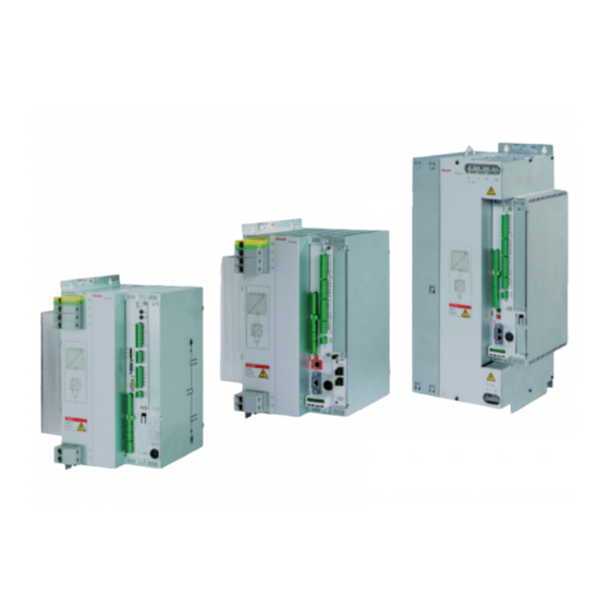
1070080028 / 12 PSI 6xxx Bosch Rexroth AG 217 / 460 Abbildungsverzeichnis Abbildungsverzeichnis Abb. 1: Beispiele: Schweißsteuerung PSI6100, PSI63C0, PSI64C0 ... Abb. 2: Übersichts-Blockschaltbild: PSI 6000 mit Trafo ..... . - Page 218 218 / 460 Bosch Rexroth AG PSI 6xxx | 1070080028 / 12 Abbildungsverzeichnis Abb. 46: Maßbild: PSI 61xx.xxx L1 .........
- Page 219 1070080028 / 12 PSI 6xxx Bosch Rexroth AG 219 / 460 Abbildungsverzeichnis Abb. 96: Master‐Slave‐Betrieb bei Verwendung der im PSG integrierten Sekundärstromsensoren ......... .
- Page 220 220 / 460 Bosch Rexroth AG PSI 6xxx | 1070080028 / 12 Notizen | Notes:...
-
Page 221: Abkürzungen
1070080028 / 12 PSI 6xxx Bosch Rexroth AG 221 / 460 Abkürzungen Abkürzungen Tab. 42: Abkürzungen und Begriffserklärungen Abkürzung Bedeutung Alternate Current. Wechselstrom. Ablaufende. Siehe FK. Bedienoberfläche Schweißen Bedienoberfläche U/I-Regler Controller Area Network; Datenbus Cycles. Siehe P. Deka-Newton. 1 daN = 10 N Direct Current. - Page 222 222 / 460 Bosch Rexroth AG PSI 6xxx | 1070080028 / 12 Abkürzungen Abkürzung Bedeutung Magnetventil. Ansteuerung für die Zangenzylinder, um die Elektroden zu schließen. Netzlast-Begrenzungs-Steuerung. Überwacht und beeinflusst die Belastung im Netz. Nachhaltezeit. Zeit nach der letzten Stromzeit, in der das Schweißgut auskühlen kann.
- Page 223 1070080028 / 12 PSI 6xxx Bosch Rexroth AG 223 / 460 Abkürzungen Abkürzung Bedeutung Startslopezeit. Zeit, in der die LST vom Anfang der 2. STZ an ansteigt. Stepper Leistungsnachstellung zur Elektrodenverschleiß-Kompen sation. Stromzeit. Man unterscheidet 1.STZ (Vorwärmstromzeit), 2.STZ (Haupt-Schweißstromzeit) und 3.STZ (Nachwärmstrom...
- Page 224 224 / 460 Bosch Rexroth AG PSI 6xxx | 1070080028 / 12 Abkürzungen Notizen | Notes:...
-
Page 225: Stichwortverzeichnis
1070080028 / 12 PSI 6xxx Bosch Rexroth AG 225 / 460 Stichwortverzeichnis Stichwortverzeichnis Belastungsdiagramm Abkürzungen, 221 6300/63C0.xxx L1/W1, I primär (ts), 104 Abmessungen, 116 6300/63C0.xxx L2/W2, I primär (ts), 105 Abschalten des Mittelfrequenz-Umrichters, 163 PSI 61xx.xxx, I primär (ED), 96 AC, 221 PSI 61xx.xxx L1/W1, I primär (ts), 97... - Page 226 226 / 460 Bosch Rexroth AG PSI 6xxx | 1070080028 / 12 Stichwortverzeichnis Elektrischer Anschluss, 133 PSI 61xx.xxx Lx/Wx, 119 Lagerung, 113 PSI 62xx.xxx, 121 LED Bereit, 201 PSI 6300/63C0.xxx Lx/Wx, 125 LED's, 50, 52 PSI 64C0.xxx, 127 Leistungsbeschreibung, 41 PSI 65xx.xxx, 131...
- Page 227 1070080028 / 12 PSI 6xxx Bosch Rexroth AG 227 / 460 Stichwortverzeichnis Programmiergerät, 137 Trafoanschluss, 137 Programmierung , 45 Transformator-Temperatur, 154 PSF, 222 Transport, 113 PSG, 11, 222 Typenschlüssel , 110 PSI, 11, 222 PSQ 6000 XQR, 91 Überblick, 39...
- Page 228 228 / 460 Bosch Rexroth AG PSI 6xxx | 1070080028 / 12 Notizen | Notes:...
-
Page 229: Table 6: Designations
1070080028 / 08 PSI 6xxx Bosch Rexroth AG 229 / 460 Contents Contents Regarding this documentation ....Validity of the documentation ...... -
Page 230: Fig. 11: "Cc Ethernet 100 Mbit" Module
230 / 460 Bosch Rexroth AG PSI 6xxx | 1070080028 / 08 Contents Product description ........ -
Page 231: Table 20: Spare Parts
1070080028 / 08 PSI 6xxx Bosch Rexroth AG 231 / 460 Contents Electrical connection of the product ..... . 7.2.1 General information on electromagnetic fields . - Page 232 232 / 460 Bosch Rexroth AG PSI 6xxx | 1070080028 / 08 Contents Troubleshooting ......
-
Page 233: Regarding This Documentation
1070080028 / 08 PSI 6xxx Bosch Rexroth AG 233 / 460 Regarding this documentation Regarding this documentation This chapter includes important information on the use of the docu mentation. " Inform yourself about the product before you work with it! - Page 234 234 / 460 Bosch Rexroth AG PSI 6xxx | 1070080028 / 08 Regarding this documentation Title Doc. no. Document type D PSG xxxx: MF welding trans 1070087062 Operating instruc formers tions Rexroth PSG xxx R911342242 Safety and user MF welding transformers...
-
Page 235: Presentation Of Information
1070080028 / 08 PSI 6xxx Bosch Rexroth AG 235 / 460 Regarding this documentation Presentation of information We use uniform icons, terms and abbreviations in this documentation. They will be explained in the following paragraphs. 1.3.1 Safety instructions Safety instructions call your attention specifically to danger potentials or risks. -
Page 236: Table 3: Danger Classes According To Ansi Z535.6
236 / 460 Bosch Rexroth AG PSI 6xxx | 1070080028 / 08 Regarding this documentation The safety instructions are classified into danger levels (danger clas Danger levels? ses). The signal word represents the danger level. Table 3: Danger classes according to ANSI Z535.6... -
Page 237: Icons
1070080028 / 08 PSI 6xxx Bosch Rexroth AG 237 / 460 Regarding this documentation 1.3.2 Icons The following icons are used to mark text passages specifically. Table 5: Icons used Icon Meaning This icon indicates a tip or an information. It helps use and operate the product optimally or understand the context better. - Page 238 238 / 460 Bosch Rexroth AG PSI 6xxx | 1070080028 / 08 Regarding this documentation Notes:...
-
Page 239: Safety Instructions
1070080028 / 08 PSI 6xxx Bosch Rexroth AG 239 / 460 Safety instructions Safety instructions This section includes important information on the safe handling of the described product. On this section The described product has been developed, manufactured, tested and documented in compliance with the EU standards. -
Page 240: Qualification Of Personnel
• operation or storage outside the specified environmental conditions (e.g. air humidity), • electrical connection does not correspond to documentation. Bosch Rexroth AG does not assume any liability for damages caused by inappropriate use. The risks resulting from inappropriate use are borne by the operator/user alone. - Page 241 1070080028 / 08 PSI 6xxx Bosch Rexroth AG 241 / 460 Safety instructions Interventions in the hardware and software of our products, unless " described otherwise in the related documentation, are reserved to our specialized personnel. Our written approval is required with respect to other persons! "...
-
Page 242: General Safety Instructions
242 / 460 Bosch Rexroth AG PSI 6xxx | 1070080028 / 08 Safety instructions General safety instructions Please not the applicable accident prevention and environmental " protection provisions. " Please note the safety instructions and regulations of the country where the product is used/applied. -
Page 243: Product- And Technology-Dependent Safety Instructions
1070080028 / 08 PSI 6xxx Bosch Rexroth AG 243 / 460 Safety instructions Product- and technology-dependent safety instructions This section contains general notes and instructions which are import ant with regard to your safety when handling the product and the tech... -
Page 244: Installation And Assembly
244 / 460 Bosch Rexroth AG PSI 6xxx | 1070080028 / 08 Safety instructions 2.6.3 Installation and assembly WARNING Dangerous electrical voltage Possibility of cardiac arrhythmia, burns, shock! " Please ensure that all plant sections worked on in the course of the assembly have been safely isolated from supply and suffi... - Page 245 1070080028 / 08 PSI 6xxx Bosch Rexroth AG 245 / 460 Safety instructions CAUTION Inappropriate fastening Possibility of reduction of personal/plant safety, function disturban ces! " Make sure that the place of installation and the method of fastening the modules are selected according to their weight! Please also note dynamic forces which may affect the product.
-
Page 246: Electrical Connection
246 / 460 Bosch Rexroth AG PSI 6xxx | 1070080028 / 08 Safety instructions 2.6.4 Electrical connection WARNING Dangerous electrical voltage Possibility of cardiac arrhythmia, burns, shock! The electrical connection may only be made by a skilled electri " cian who observes the valid safety regulations, the mains voltage and the maximum current consumption of the plant sections. - Page 247 1070080028 / 08 PSI 6xxx Bosch Rexroth AG 247 / 460 Safety instructions WARNING Inappropriate or missing evaluation of error messages Possibility of reduction of personal/plant safety, function disturban ces! " Many messages can be configured freely in the WT depending on your requirements, either as”warning”...
-
Page 248: Operating The Product
248 / 460 Bosch Rexroth AG PSI 6xxx | 1070080028 / 08 Safety instructions WARNING Defective connection of cables Possibility of reduction of safety of persons/systems, function disturbances/restrictions! " All conductor cross-sections should be rated in accordance with the installed load. - Page 249 1070080028 / 08 PSI 6xxx Bosch Rexroth AG 249 / 460 Safety instructions WARNING High dynamic forces and extremely fast movements Danger of impacts, bruises, entanglement and burns! You should always be aware of the possibility that motions can be "...
-
Page 250: Retrofits And Modifications By The Operator
250 / 460 Bosch Rexroth AG PSI 6xxx | 1070080028 / 08 Safety instructions 2.6.6 Retrofits and modifications by the operator WARNING Modification of the product Possibility of reduction of safety of persons/systems, function disturbances/restrictions! Modifications of the product are normally not permitted. -
Page 251: Maintenance And Repair
1070080028 / 08 PSI 6xxx Bosch Rexroth AG 251 / 460 Safety instructions 2.6.7 Maintenance and repair WARNING Dangerous Electrical Voltage Possibility of cardiac arrhythmia, burns, shock! " Unless described otherwise, maintenance work must be per formed on inactive systems that have been sufficiently protected... -
Page 252: Declaration Of Conformity / Ce Marking
252 / 460 Bosch Rexroth AG PSI 6xxx | 1070080028 / 08 Safety instructions CAUTION Improper handling of lithium batteries Possibility of burns, explosion! Do not open lithium batteries by force. " " Do not recharge used lithium batteries. Do not heat lithium batteries to above 100 degrees Centigrade. -
Page 253: Obligations Of The Operator
1070080028 / 08 PSI 6xxx Bosch Rexroth AG 253 / 460 Safety instructions Obligations of the operator The operator is responsible for the system. Therefore he has to • ensure that the system is operated according to its intended use, •... - Page 254 254 / 460 Bosch Rexroth AG PSI 6xxx | 1070080028 / 08 Safety instructions Notes:...
-
Page 255: General Information On Damage To Property And Products
1070080028 / 08 PSI 6xxx Bosch Rexroth AG 255 / 460 General information on damage to property and products General information on damage to property and products The present section includes information which is important for protec tion against damage to property and products. -
Page 256: Installation And Assembly
256 / 460 Bosch Rexroth AG PSI 6xxx | 1070080028 / 08 General information on damage to property and products Installation and assembly NOTICE Improper handling of devices with water cooling Leakage in the cooling circuit possible! " Make sure that the water connections and hose bridges (hose bridge: refer to fig. - Page 257 1070080028 / 08 PSI 6xxx Bosch Rexroth AG 257 / 460 General information on damage to property and products NOTICE Overheating or condensation due to insufficient cooling Possibility of temporary interruption of the welding process, a re duced useful life of the product, destruction of the device, damage to the electrical equipment, unexpected plant reactions! "...
-
Page 258: Electrical Connection
258 / 460 Bosch Rexroth AG PSI 6xxx | 1070080028 / 08 General information on damage to property and products Electrical connection NOTICE Incorrect voltage supply Possibility of damage to the electrical equipment! " Check whether the supply voltage coincides with the nominal vol... - Page 259 1070080028 / 08 PSI 6xxx Bosch Rexroth AG 259 / 460 General information on damage to property and products NOTICE Electrostatic charge Possibility of damage to the electrical equipment! " Observe all precautions for ESD protection when handling modu les and components and avoid electrostatic discharge.
-
Page 260: Operation
260 / 460 Bosch Rexroth AG PSI 6xxx | 1070080028 / 08 General information on damage to property and products Operation NOTICE High-frequency interference Possibility of interference with other devices in the environment! Make sure that no other devices or their functioning can be affec... -
Page 261: Maintenance And Repair
1070080028 / 08 PSI 6xxx Bosch Rexroth AG 261 / 460 General information on damage to property and products Maintenance and repair NOTICE Plugging or unplugging modules or connectors/terminals into/from live systems Possibility of damage to the electrical equipment, unexpected plant reactions! Unless described otherwise, never unplug or plug any connec... - Page 262 262 / 460 Bosch Rexroth AG PSI 6xxx | 1070080028 / 08 General information on damage to property and products Notes:...
-
Page 263: Scope Of Delivery
1070080028 / 08 PSI 6xxx Bosch Rexroth AG 263 / 460 Scope of delivery Scope of delivery The scope of delivery is dependent on the order. Therefore we cannot provide any globally valid information on the scope of your specific delivery. - Page 264 264 / 460 Bosch Rexroth AG PSI 6xxx | 1070080028 / 08 Scope of delivery Notes:...
-
Page 265: Information On This Product
1070080028 / 08 PSI 6xxx Bosch Rexroth AG 265 / 460 Information on this product Information on this product The units of the PSI 6xxx series are Class A welding equipment and in clude by default • weld timer (WT), and •... -
Page 266: Table 8: Overview Of The Types Of Power Units
266 / 460 Bosch Rexroth AG PSI 6xxx | 1070080028 / 08 Information on this product • Broad variety of available I/O interfaces for communication with PLC, robot or for connection of machine control panel • Optionally available field bus interfaces for communication with a higher host level •... -
Page 267: Description Of Performance
1070080028 / 08 PSI 6xxx Bosch Rexroth AG 267 / 460 Information on this product Description of performance • User interface for operation, programming and diagnosis: - complete graphical user interface BOS, - system requirements: executable on PCs with operating systems Windows 7 with Service Pack 1 (32 Bit, 64 Bit) Windows 8 or 8.1... - Page 268 268 / 460 Bosch Rexroth AG PSI 6xxx | 1070080028 / 08 Information on this product - UIR (adaptive controller; optional) PHA and KSR control modes can be separately configured for each weld time (mixed operation). UIR only in MainWLD.
- Page 269 1070080028 / 08 PSI 6xxx Bosch Rexroth AG 269 / 460 Information on this product • General overview of the welding equipment in the plant image • Global timer display of - Start inhibit (P) - Weld internal on (P)
-
Page 270: Product Description
270 / 460 Bosch Rexroth AG PSI 6xxx | 1070080028 / 08 Information on this product Product description Timer and power unit assembled in a joint housing. PSI 6500.XXX PSI 6500.XXX PSI 6500.XXX PSI 6500.XXX PSI 6500.XXX PSI 6500.XXX PSI 6500.XXX PSI 6200.XXX... -
Page 271: Programming And Operation
1070080028 / 08 PSI 6xxx Bosch Rexroth AG 271 / 460 Information on this product 5.2.1 Programming and operation All necessary parameters are always kept in a battery-buffered RAM in side the timer. Operation, programming and diagnosis are performed via the connec... -
Page 272: Functional Principle Of Medium-Frequency Welding
272 / 460 Bosch Rexroth AG PSI 6xxx | 1070080028 / 08 Information on this product 5.2.2 Functional principle of medium-frequency welding PSI 6xxx 1000 Transformer- Welding Weld timer MF inverter rectifier equipment Fig. 2:Block diagram overview: PSI 6000 with transformer The MF inverter integrated in the PSI controls the welding transformer by a bipolar, rectangular voltage with a frequency of 1000 Hz. -
Page 273: Fig. 4:Secondary Rectification By The Psg Transformer
1070080028 / 08 PSI 6xxx Bosch Rexroth AG 273 / 460 Information on this product Medium‐frequency inverter resulting welding output voltage current 1 ms Fig. 4:Secondary rectification by the PSG transformer Primary voltage small pulse width PRIM f = 1 kHz resulting se... -
Page 274: Structure
274 / 460 Bosch Rexroth AG PSI 6xxx | 1070080028 / 08 Information on this product 5.2.3 Structure The power unit is permanently installed in the left part of the housing, the timer module in the right side of the housing. - Page 275 1070080028 / 08 PSI 6xxx Bosch Rexroth AG 275 / 460 Information on this product For information on assembly and connection, please refer to Sec tion 7 from page 341. Additional documents are available for the description of type- dependent functions/connections of the timer (refer to page 233).
-
Page 276: Partial Front-Panel View Psi 6X00.Xxx
276 / 460 Bosch Rexroth AG PSI 6xxx | 1070080028 / 08 Information on this product 5.2.3.1 Partial front-panel view PSI 6x00.xxx LOGIC LED; green. Is on when 24 V (logic power supply) is available. DC LINK CIRCUIT LED; red (only operative if LOGIC LED is illumina... - Page 277 1070080028 / 08 PSI 6xxx Bosch Rexroth AG 277 / 460 Information on this product The LEDs can only display the status of the WT if the logic supply voltage is present! NOTICE Arbitrary pressing of the boot button Possibility of negative effects on the ongoing production! Do not ever activate the boot button during ongoing production.
-
Page 278: Partial Front-Panel View Psi 6Xcx.xxx
278 / 460 Bosch Rexroth AG PSI 6xxx | 1070080028 / 08 Information on this product 5.2.3.2 Partial front-panel view PSI 6xCx.xxx 24 V output for power supply to I/O module (refer to page 367). 24 V output of the internal voltage source (refer to page 366). - Page 279 1070080028 / 08 PSI 6xxx Bosch Rexroth AG 279 / 460 Information on this product The LEDs can only display the status of the WT if the logic supply voltage is present!
-
Page 280: Modules
280 / 460 Bosch Rexroth AG PSI 6xxx | 1070080028 / 08 Information on this product 5.2.4 Modules 5.2.4.1 AnyBus module ”ProfiNet IO“ Features: • Suitable for PSI 6xCx.xxx (slot X7E1) • ProfiNet (RT classification, conformity class B) • Fast Ethernet (100 Mbit/s), full-duplex mode •... - Page 281 1070080028 / 08 PSI 6xxx Bosch Rexroth AG 281 / 460 Information on this product LED for module status: Off: module not initialized Green: module is working normally Green, flashing once: diagnostic event detected Green, flashing twice: triggered by SW tool for module identification...
-
Page 282: Anybus Module "Cc Ethernet 100 Mbit
282 / 460 Bosch Rexroth AG PSI 6xxx | 1070080028 / 08 Information on this product 5.2.4.2 AnyBus module ”CC Ethernet 100 Mbit” Features: • Suitable for PSI 6xCx.xxx (slot X7E1) • Fast Ethernet (100 Mbit/s), full-duplex mode • Available as 1-port or 2-port variant. 2-port variant with integrated switch •... -
Page 283: Cc Ethernet 100 Mbit" Module
1070080028 / 08 PSI 6xxx Bosch Rexroth AG 283 / 460 Information on this product 5.2.4.3 ”CC Ethernet 100 Mbit“ module Features: • Suitable for PSI 6xxx.xxx (slot for field bus module) • Ethernet plug-in module on the basis of an AnyBus module. -
Page 284: Cc Profinet" Module
284 / 460 Bosch Rexroth AG PSI 6xxx | 1070080028 / 08 Information on this product 5.2.4.4 ”CC ProfiNet“ module Features: • Suitable for PSI 6xxx.xxx (slot for fieldbus module) • ProfiNet plug-in module on the basis of an AnyBus module. -
Page 285: Module „Profinet-Irt, 2 Port (M40 Module)
1070080028 / 08 PSI 6xxx Bosch Rexroth AG 285 / 460 Information on this product 5.2.4.5 Module „Profinet-IRT, 2 port (M40 module)“ Features: • Part number 1070094170 • Suitable for PSI 6xxx.xxx (slot for fieldbus module) • Same as CC Profinet only as 2 port variant with ProfiNet IRT •... -
Page 286: Module "Optical Fiber Profinet
286 / 460 Bosch Rexroth AG PSI 6xxx | 1070080028 / 08 Information on this product 5.2.4.6 Module ”Optical fiber ProfiNet“ Features: • Suitable for PSI 6xxx.xxx (slot for fieldbus module) • Optical fiber ProfiNet withdrawable module • ProfiNet interface according to IRT classification, conformity class C •... -
Page 287: Module „Profinet-Irt, Lwl (M40 Module)
1070080028 / 08 PSI 6xxx Bosch Rexroth AG 287 / 460 Information on this product 5.2.4.7 Module „Profinet-IRT, LWL (M40 module)“ Features: • Part number 1070093995 • Suitable for PSI 6xxx.xxx (slot for fieldbus module) • Same as Optical fiber Profinet with optic connection ProfiNet IRT LWL (M40 module). -
Page 288: Diagnosis Module
288 / 460 Bosch Rexroth AG PSI 6xxx | 1070080028 / 08 Information on this product 5.2.4.8 Diagnosis module Only in combination with PSI 6xCx.xxx. 8-digit display Enter Fig. 16: Diagnosis module: Front panel view Functions: • Display the timer status, type, time, Ethernet configuration •... -
Page 289: Fig. 17: Diagnosis Module: Main Menu
1070080028 / 08 PSI 6xxx Bosch Rexroth AG 289 / 460 Information on this product Hardware faults cannot be reset. Self-acknowledging faults are automatically reset by the system when the cause of the fault is no longer present (e.g. line voltage off/ on). -
Page 290: Fig. 18: Diagnosis Module: Ethernet Menu
290 / 460 Bosch Rexroth AG PSI 6xxx | 1070080028 / 08 Information on this product ETHERNET main menu item: Display showing the Ethernet configuration of the AnyBus module (ETHERN.1) or - if inserted - of the ”CC Ethernet 100 Mbit“ module (ETHERN.2). - Page 291 1070080028 / 08 PSI 6xxx Bosch Rexroth AG 291 / 460 Information on this product Reset faults Press the "Enter" key. The display now shows "Err Quit". Press the "ESC" key to cancel acknowledgement, or the "Enter" key to acknowledge the fault.
-
Page 292: E/A Disk R2Ed" And "E/A Disk R4Ed" I/O Module
292 / 460 Bosch Rexroth AG PSI 6xxx | 1070080028 / 08 Information on this product 5.2.4.9 I/O module ”E/A DISK R2ED” and ”E/A DISK R4ED“ Features: • 26 discrete inputs (24 V • 1 output as switched relay (1 x ON) •... - Page 293 1070080028 / 08 PSI 6xxx Bosch Rexroth AG 293 / 460 Information on this product Discrete signal outputs and inputs Connection: E/A DISK R2ED: X11:8-pole; X12:14-pole; X13:12-pole; X14:16-pole E/A DISK R4ED: X21:8-pole; X22:14-pole; X23:12-pole; X24:16-pole STKK, grid 3.5 mm, max. 1.5 mm Mating connectors are comprised in the delivery.
-
Page 294: Fig. 19: Front Panel View: "E/A Disk R2Ed" I/O Module
294 / 460 Bosch Rexroth AG PSI 6xxx | 1070080028 / 08 Information on this product Signal inputs I0 to I13 (24 V ), with control LED 2x voltage output for power supply to the ext. input circuits (internally tapped from X10) -
Page 295: E/A Disk" I/O Module
1070080028 / 08 PSI 6xxx Bosch Rexroth AG 295 / 460 Information on this product 5.2.4.10 ”E/A DISK” I/O module Features: • 21 discrete inputs (24 V • 13 discrete outputs (24 V Function: • Coupling of discrete I/O signals. -
Page 296: Fig. 20: Front Panel View: "E/A Disk" I/O Module
296 / 460 Bosch Rexroth AG PSI 6xxx | 1070080028 / 08 Information on this product Miniature fuse M 1.6 A; for fusing output O0 Miniature fuse M 1.6 A; for fusing the outputs O1 to O12 Signal inputs I0 to I13 (24 V ), with control LED 2x voltage output for power supply to the ext. -
Page 297: E/A Disk 2R" And "E/A Disk 4R" I/O Modules
1070080028 / 08 PSI 6xxx Bosch Rexroth AG 297 / 460 Information on this product 5.2.4.11 ”E/A DISK 2R” and ”E/A DISK 4R“ I/O modules Features: • 22 discrete inputs (24 V ) each • 1 output each as switched relay (1 x ON) •... - Page 298 298 / 460 Bosch Rexroth AG PSI 6xxx | 1070080028 / 08 Information on this product Discrete signal outputs and inputs Connection: E/A DISK 2R: X11: 18-pole; X12: 8-pole; X13: 16-pole E/A DISK 4R: X21: 18-pole; X22: 8-pole; X23: 16-pole STKK, grid 3.5 mm, max.
-
Page 299: Fig. 21: Front Panel View: "E/A Disk 2R" / "E/A Disk 4R" I/O Module
1070080028 / 08 PSI 6xxx Bosch Rexroth AG 299 / 460 Information on this product Miniature fuse M 1.6 A; for fusing the outputs O0 and O13 to O15 Miniature fuse M 1.6 A; for fusing the outputs O1 to O10... - Page 300 300 / 460 Bosch Rexroth AG PSI 6xxx | 1070080028 / 08 Information on this product Notes:...
-
Page 301: E/A Ibs Opc With Optical Fiber" (Interbus-S) I/O Module
1070080028 / 08 PSI 6xxx Bosch Rexroth AG 301 / 460 Information on this product 5.2.4.12 ”E/A IBS OPC with optical fiber” (INTERBUS-S) I/O module Only in combination with PSI 6x00.xxx. Features: • 8 discrete inputs (24 V • 8 discrete outputs (24 V •... - Page 302 302 / 460 Bosch Rexroth AG PSI 6xxx | 1070080028 / 08 Information on this product Voltage supply Connection: X10: 4-pole; STKK, grid 3.5 mm, max. 1.5 mm Mating connector is comprised in the delivery. Cable length: (from power source to consumer) max.
-
Page 303: Fig. 22: Front Panel View: "E/A Ibs Opc With Optical Fiber" I/O Module
1070080028 / 08 PSI 6xxx Bosch Rexroth AG 303 / 460 Information on this product Diagnosis messages of the module: TR: Transmit/Receive; no meaning in this case. CC: Cable check; bus connection (coming from the previous IB‐S node) exists. Is switched off in the case of reset at the master. -
Page 304: Fig. 23: "E/A Ibs Opc With Optical Fiber" I/O Module: Setting Of Transmission Power And The Baud Rate
304 / 460 Bosch Rexroth AG PSI 6xxx | 1070080028 / 08 Information on this product Setting of baud rate and transmission power " The transmission power must not be changed without consulting with us. I/O module Front side Transmission power... -
Page 305: E/A Ibs Fern" (Interbus-S) I/O Module
1070080028 / 08 PSI 6xxx Bosch Rexroth AG 305 / 460 Information on this product 5.2.4.13 ”E/A IBS FERN” (INTERBUS-S) I/O module Features: • 8 discrete inputs (24 V • 8 discrete outputs (24 V • INTERBUS-S connection via copper cable Function: •... -
Page 306: Fig. 24: Front Panel View: "E/A Ibs Fern (Remote)" I/O Module
306 / 460 Bosch Rexroth AG PSI 6xxx | 1070080028 / 08 Information on this product INTERBUS-S connection IN (coming from previous IB-S node) - For pin assignment, refer to page 307 Diagnostic messages of the module: - US: Unit Supply; power supply available - RC: Remote bus Check;... -
Page 307: Fig. 25: Terminal Assignment Of The Interbus-S Ports
1070080028 / 08 PSI 6xxx Bosch Rexroth AG 307 / 460 Information on this product Weld timer previous X13 (IBS‐IN) INTERBUS-S node /DO1 /DI1 Male connector Screen continuity through large-area connection to metal housing of the plug connection X12 (IBS‐OUT) - Page 308 308 / 460 Bosch Rexroth AG PSI 6xxx | 1070080028 / 08 Information on this product Notes:...
-
Page 309: E/A Ibs X_Fern_8Ea" (Interbus-S) I/O Module
1070080028 / 08 PSI 6xxx Bosch Rexroth AG 309 / 460 Information on this product 5.2.4.14 ”E/A IBS X_FERN_8EA” (INTERBUS-S) I/O module Features: • 8 discrete inputs (24 V • 8 discrete outputs (24 V • INTERBUS-S via copper cable Function: •... -
Page 310: Fig. 26: Front Panel View: "E/A Ibs X_Fern_8Ea" I/O Module
310 / 460 Bosch Rexroth AG PSI 6xxx | 1070080028 / 08 Information on this product Cable type: copper cable, according to INTERBUS-S spe cification ID code: 47 (dec.) INTERBUS-S connection IN (coming from previous IB-S node) - For pin assignment, refer to page 311 Diagnostic messages of the module: : Unit Supply;... -
Page 311: Fig. 27: Terminal Assignment Of The Interbus-S Ports
1070080028 / 08 PSI 6xxx Bosch Rexroth AG 311 / 460 Information on this product Weld timer previous X13 (IBS‐IN) INTERBUS-S node /DO1 /DI1 Male connector Screen continuity through large-area connection to metal housing of the plug connection X12 (IBS‐OUT) - Page 312 312 / 460 Bosch Rexroth AG PSI 6xxx | 1070080028 / 08 Information on this product Notes:...
-
Page 313: Dev-Net" (Devicenet) I/O Module
1070080028 / 08 PSI 6xxx Bosch Rexroth AG 313 / 460 Information on this product 5.2.4.15 ”DEV-NET” (DeviceNet) I/O module Features: • 8 discrete inputs (24 V • 8 discrete outputs (24 V • DeviceNet connection via bus copper cable Function: •... -
Page 314: Fig. 28: Front Panel View: "Dev-Net" I/O Module
314 / 460 Bosch Rexroth AG PSI 6xxx | 1070080028 / 08 Information on this product - Diagnostic messages of the module: (according to DeviceNet specification) - NA: Switches for setting the node address (MAC ID) - DR: Switches for setting the baud rate (each according to DeviceNet specification) Value (dec.) -
Page 315: Comnetm-Dp" (Profibus-Dp) I/O Module
1070080028 / 08 PSI 6xxx Bosch Rexroth AG 315 / 460 Information on this product 5.2.4.16 ”ComnetM-DP" (PROFIBUS-DP) I/O module Features: • 16 discrete inputs (24 V • 16 discrete outputs (24 V • PROFIBUS-DP connection via bus copper cable Function: •... -
Page 316: Fig. 29: Front Panel View: "Comnetm-Dp" I/O Module
316 / 460 Bosch Rexroth AG PSI 6xxx | 1070080028 / 08 Information on this product - Diagnostic messages of the module: (according to PROFIBUS specification) - Bus connection. Pin assignment: Shield RXD / TXD ‐P CNTR ‐P DGND RXD / TXD ‐N - DP‐ADR: Setting of the PROFIBUS-DP address. -
Page 317: Ui Controller Module (Psq 6000 Xqr)
1070080028 / 08 PSI 6xxx Bosch Rexroth AG 317 / 460 Information on this product 5.2.4.17 UI controller module (PSQ 6000 XQR) Only required for necessary function/controller module in connec tion with PSI 6x00.xxx. Features: • Optional plug-in board for enhanced functions of a PSI 6x00.xxx weld timer. -
Page 318: Fig. 30: Front Panel View: "Psq 6000 Xqr" Ui Controller Module
318 / 460 Bosch Rexroth AG PSI 6xxx | 1070080028 / 08 Information on this product Fig. 30: Front panel view: "PSQ 6000 XQR“ UI controller module Inputs for connection of screened voltage Display CAN bus communication: measuring leads U1 and U2. - Page 319 1070080028 / 08 PSI 6xxx Bosch Rexroth AG 319 / 460 Information on this product Notes:...
-
Page 320: Load And Rating
320 / 460 Bosch Rexroth AG PSI 6xxx | 1070080028 / 08 Information on this product Load and rating 5.3.1 Basics In general, semi‐conductors have an almost infinite life if they are used within their specifications. As a result of thermal load, however, mechanical forces act on the semi‐conductor chips, and this may influence their life depending on the... - Page 321 1070080028 / 08 PSI 6xxx Bosch Rexroth AG 321 / 460 Information on this product In addition, check the maximum permitted welding current for a wel " ding time for a computational useful life of 10 million spots. There are diagrams showing the limit at 10% duty cycle and are considered to be a typical transformer/secondary resistance combi...
-
Page 322: Load Diagrams
322 / 460 Bosch Rexroth AG PSI 6xxx | 1070080028 / 08 Information on this product 5.3.3 Load diagrams For descriptions of load diagrams, refer to page 320 et seq. Diagram basis: - computational peak current at a welding time of 0.1 s and 1 million spots - Ambient temperature of 45°C... - Page 323 1070080028 / 08 PSI 6xxx Bosch Rexroth AG 323 / 460 Information on this product Diagram basis: - Ambient temperature of 45°C - PSG 3100 - 10% duty cycle - 200 μOhm load Weld time in sec. 10 million spots 1 million spots Fig.
- Page 324 324 / 460 Bosch Rexroth AG PSI 6xxx | 1070080028 / 08 Information on this product Diagram basis: - Ambient temperature of 45°C - PSG 3100 - 10% duty cycle - 200 μOhm load Weld time in sec. 10 million spots 1 million spots Fig.
- Page 325 1070080028 / 08 PSI 6xxx Bosch Rexroth AG 325 / 460 Information on this product Notes:...
-
Page 326: Fig. 34: Permitted Primary Current Depending On The Duty Cycle: Psi 62Xx
326 / 460 Bosch Rexroth AG PSI 6xxx | 1070080028 / 08 Information on this product Diagram basis: - computational peak current at a welding time of 0.1 s and 1 million spots - Ambient temperature of 45°C 1600 1400... - Page 327 1070080028 / 08 PSI 6xxx Bosch Rexroth AG 327 / 460 Information on this product Diagram basis: - Ambient temperature of 45°C - 2 x PSG 3100 in parallel - 10% duty cycle - 50 μOhm load 1400 1200 1000 Weld time in sec.
-
Page 328: Fig. 36: Permitted Primary Current Depending On The Duty Cycle: Psi 6300/63C0.Xxx L1/W1
328 / 460 Bosch Rexroth AG PSI 6xxx | 1070080028 / 08 Information on this product Diagram basis: - computational peak current at a welding time of 0.1 s and 1 million spots - Ambient temperature of 45°C 1,00 10,00... - Page 329 1070080028 / 08 PSI 6xxx Bosch Rexroth AG 329 / 460 Information on this product Diagram basis: - computational peak current at a welding time of 0.1 s and 1 million spots - Ambient temperature of 45°C 1,00 10,00 100,00...
-
Page 330: Fig. 38: Permitted Primary Current Depending On The Welding Time: Psi 6300/63C0.Xxx L1/W1
330 / 460 Bosch Rexroth AG PSI 6xxx | 1070080028 / 08 Information on this product Diagram basis: - Ambient temperature of 45°C - PSG 3100 - 10% duty cycle - 100 μOhm load Weld time in sec. 10 million spots 1 million spots Fig. -
Page 331: Fig. 39: Permitted Primary Current Depending On The Welding Time: Psi 6300/63C0.Xxx L2/W2
1070080028 / 08 PSI 6xxx Bosch Rexroth AG 331 / 460 Information on this product Diagram basis: - Ambient temperature of 45°C - PSG 3100 - 10% duty cycle - 100 μOhm load Weld time in sec. 10 million spots 1 million spots Fig. -
Page 332: Fig. 40: Permitted Primary Current Depending On The Duty Cycle: Psi 64Xx
332 / 460 Bosch Rexroth AG PSI 6xxx | 1070080028 / 08 Information on this product Diagram basis: - computational peak current at a welding time of 0.1 s and 1 million spots - Ambient temperature of 45°C - 2 x PSG 6250 in parallel - 66 μOhm load... - Page 333 1070080028 / 08 PSI 6xxx Bosch Rexroth AG 333 / 460 Information on this product Diagram basis: - Ambient temperature of 45°C - 2 x PSG 6250 in parallel - 10% duty cycle - 66 μOhm load 1900 1800 1700...
-
Page 334: Fig. 42: Permitted Primary Current Depending On The Duty Cycle: Psi 65Xx
334 / 460 Bosch Rexroth AG PSI 6xxx | 1070080028 / 08 Information on this product Diagram basis: - computational peak current at a welding time of 0.1 s and 1 million spots - Ambient temperature of 45°C 2600 2400... - Page 335 1070080028 / 08 PSI 6xxx Bosch Rexroth AG 335 / 460 Information on this product Diagram basis: - Ambient temperature of 45°C - 4 x PSG 3100 in parallel - 10% duty cycle - 25 μOhm load 2600 2400 2200...
-
Page 336: Identification Of The Product
336 / 460 Bosch Rexroth AG PSI 6xxx | 1070080028 / 08 Information on this product Identification of the product 5.4.1 Type designation The type designation provides information on the product variant: PS 6_ _ _._ _ _ _ _ Line voltage range... -
Page 337: Type Plate
1070080028 / 08 PSI 6xxx Bosch Rexroth AG 337 / 460 Information on this product 5.4.2 Type plate Fig. 45: Type plate device Table 17: Type plate device name Field Name Customer logo Material number Type designation Serial number Plant... - Page 338 338 / 460 Bosch Rexroth AG PSI 6xxx | 1070080028 / 08 Information on this product Notes:...
-
Page 339: Transport And Storage
1070080028 / 08 PSI 6xxx Bosch Rexroth AG 339 / 460 Transport and storage Transport and storage Please note the instructions on transport in the chapter ”Safety in " structions” on page 243. " Please note the instructions on transport and storage in the chapter ”General information on damage to property and products”... - Page 340 340 / 460 Bosch Rexroth AG PSI 6xxx | 1070080028 / 08 Transport and storage Notes:...
-
Page 341: Assembly
1070080028 / 08 PSI 6xxx Bosch Rexroth AG 341 / 460 Assembly Assembly Assembling the product Information on installation conditions (e.g. orientation, permitted am bient temperatures) are provided in Chapter 15 on page 429 et seq. Information on dimensions, necessary cutouts and screw fastenings are provided in Section 7.1.1 starting on page 342. -
Page 342: Dimensioned Drawings And Locations Of Connections
342 / 460 Bosch Rexroth AG PSI 6xxx | 1070080028 / 08 Assembly 7.1.1 Dimensioned drawings and locations of connections Side view, right Front view (Front side) 25,5 Accessory kit for alternative mounting. Refer to page 414. Seal face. Flat gasket with 3mm thickness required. -
Page 343: Fig. 47: Dimensioned Drawing: Psi 61Xx.xxx L2
1070080028 / 08 PSI 6xxx Bosch Rexroth AG 343 / 460 Assembly Side view, right Front view (Front side) Accessory kit for alternative mounting. Refer to page 414. Seal face. Flat gasket with 3mm thickness required. Recommended mounting cut-out in... -
Page 344: Fig. 48: Dimensioned Drawing: Psi 61Xx.xxx Wx
344 / 460 Bosch Rexroth AG PSI 6xxx | 1070080028 / 08 Assembly Side view, right Front view (Front side) Accessory kit for alternative mounting. Refer to page 414. Seal face. Flat gasket with 3mm thickness required. Recommended mounting cut-out in case... - Page 345 1070080028 / 08 PSI 6xxx Bosch Rexroth AG 345 / 460 Assembly from mains Side view, right all connection terminals max. 50 mm to the welding transformer Fig. 49: Location of the mains and transformer connections: PSI 61xx.xxx Lx/Wx To find more important information: please refer to section 7.3 page 386...
-
Page 346: Fig. 51: Dimensioned Drawing: Psi 62Xx.xxx W1
346 / 460 Bosch Rexroth AG PSI 6xxx | 1070080028 / 08 Assembly Side view, right Front view (Front side) Ventilation clearance Ventilation clearance All dimensions in mm. Dimensions without tolerance: $0.5 Fig. 51: Dimensioned drawing: PSI 62xx.xxx W1... -
Page 347: Fig. 52: Location Of Mains And Transformer Connection: Psi 62Xx.xxx W1
1070080028 / 08 PSI 6xxx Bosch Rexroth AG 347 / 460 Assembly from mains Front view Connection from above Connection terminals max. 95 mm U1 V1 W1 U2 V2 Connection terminals max. 95 mm Connection from below to MF welding transformer... -
Page 348: Fig. 53: Location Of Cooling Water Connection: Psi 62Xx.xxx W1
348 / 460 Bosch Rexroth AG PSI 6xxx | 1070080028 / 08 Assembly Front view Cooling water connections: rear inlet front outlet To find more important information: please refer to section 7.3 page 386 Fig. 53: Location of cooling water connection: PSI 62xx.xxx W1... -
Page 349: Fig. 54: Dimensioned Drawing: Psi 6300/63C0.Xxx Lx
1070080028 / 08 PSI 6xxx Bosch Rexroth AG 349 / 460 Assembly Side view, right Front view (Front side) Accessory kit for alternative mounting. Refer to page 414. Seal face. Flat gasket with 3mm thickness required. Recommended mounting cut-out in case... -
Page 350: Fig. 55: Dimensioned Drawing: Psi 6300/63C0.Xxx Wx
350 / 460 Bosch Rexroth AG PSI 6xxx | 1070080028 / 08 Assembly Side view, right Front view (Front side) Accessory kit for alternative mounting. Refer to page 414. Seal face. Flat gasket with 3mm thickness required. Recommended mounting cut-out in case... -
Page 351: Fig. 57: Location Of Cooling Water Connection: Psi 6300/63C0.Xxx Wx
1070080028 / 08 PSI 6xxx Bosch Rexroth AG 351 / 460 Assembly from mains Side view, right all connection terminals max. 50 mm to the welding transformer Fig. 56: Location of mains and transformer connection: PSI 6300/63C0.xxx Lx/Wx To find more important information: please refer to section 7.3 page 386... -
Page 352: Fig. 58: Dimensioned Drawing: Psi 64C0.Xxx W1
352 / 460 Bosch Rexroth AG PSI 6xxx | 1070080028 / 08 Assembly Side view, right Front view (Front side) Ventilation clearance Ventilation clearance All dimensions in mm. Dimensions without tolerance: $0.5 Fig. 58: Dimensioned drawing: PSI 64C0.xxx W1... -
Page 353: Fig. 59: Location Of Mains And Transformer Connection: Psi 64C0.Xxx W1
1070080028 / 08 PSI 6xxx Bosch Rexroth AG 353 / 460 Assembly from mains Front view Connection from above Connection terminals max. 95 mm U1 V1 W1 U2 V2 Connection terminals max. 95 mm Connection from below to MF welding transformer... -
Page 354: Fig. 60: Location Of Cooling Water Connection: Psi 64C0.Xxx W1
354 / 460 Bosch Rexroth AG PSI 6xxx | 1070080028 / 08 Assembly Front view Cooling water connections: rear inlet front outlet To find more important information: please refer to section 7.3 page 386 Fig. 60: Location of cooling water connection: PSI 64C0.xxx W1... - Page 355 1070080028 / 08 PSI 6xxx Bosch Rexroth AG 355 / 460 Assembly Notes:...
-
Page 356: Fig. 61: Dimensioned Drawing: Psi 65Xx.xxx W1
356 / 460 Bosch Rexroth AG PSI 6xxx | 1070080028 / 08 Assembly Side view, right Front view Rear view (Front side) 194,5 for M6 Side view, left Bore-hole pattern 30,75 $ 0.2 $ 0.2 Hose bridge: Do not squash, pull, charge Front view For bolts M6. -
Page 357: Fig. 62: Location Of Mains And Transformer Connection: Psi 65Xx.xxx W1
1070080028 / 08 PSI 6xxx Bosch Rexroth AG 357 / 460 Assembly from mains Front view U1 V1 W1 Connection via cable lugs. 1 screw M10 per connection. 2 to 4 cables; 120 mm each Protective cover Connection via cable lugs. -
Page 358: Fig. 63: Location Of Cooling Water Connection: Psi 65Xx.xxx W1
358 / 460 Bosch Rexroth AG PSI 6xxx | 1070080028 / 08 Assembly Front view Hose bridge Cooling water connections: inlet outlet To find more important information: please refer to section 7.3 page 386 Fig. 63: Location of cooling water connection: PSI 65xx.xxx W1... -
Page 359: Electrical Connection Of The Product
1070080028 / 08 PSI 6xxx Bosch Rexroth AG 359 / 460 Assembly Electrical connection of the product " Please note the safety instructions relevant for electrical connection in Section 2.6.4 starting on page 246 and in Sect. 3.3 starting on page 258. -
Page 360: Interference Suppression
360 / 460 Bosch Rexroth AG PSI 6xxx | 1070080028 / 08 Assembly 7.2.2 Interference suppression Noise is caused by switching peaks and can interfere with the timer di rectly or through coupling with connecting lines. Therefore, measures must be taken to suppress noise. -
Page 361: Fig. 65: Typical Curve Of The Mains Voltage (Top) And The Related Mains Current (Bottom)
1070080028 / 08 PSI 6xxx Bosch Rexroth AG 361 / 460 Assembly When operating medium-frequency inverters a harmonic load must be accounted for in the mains system. Typical 300 Hz Fig. 65: Typical curve of the mains voltage (top) and the related mains cur... - Page 362 362 / 460 Bosch Rexroth AG PSI 6xxx | 1070080028 / 08 Assembly Please note the following prescriptions in the context of electrical " connection: • Operation of the inverter is only intended for use in buildings/ property with an operating current greater than/equal to 100 A for each phase.
-
Page 363: Transformer Connection (Primary Circuit)
1070080028 / 08 PSI 6xxx Bosch Rexroth AG 363 / 460 Assembly 7.2.4 Transformer connection (primary circuit) " Attach the cables for U2 and V2 with aluminum brackets and always guide the cables - if necessary - through the housing metal together (because of inductive temperature rise). -
Page 364: Fig. 67: Connection Of Programming Terminal Via X3C
364 / 460 Bosch Rexroth AG PSI 6xxx | 1070080028 / 08 Assembly X3C (V24/RS232 interface, miniature DIN) Only in connection with PSI 6xCx.xxx! Connection: to X3C; miniature DIN, 8-pole, male connector Cable length: max. 20 m (with recommended cable type) Cable type: shielded, core area min. -
Page 365: Vdc Logic Supply (X4, Input)
1070080028 / 08 PSI 6xxx Bosch Rexroth AG 365 / 460 Assembly 7.2.6 24 V logic supply (X4, input) Connection: to X4; STKK, grid 3.5 mm, 14-pole, max. 1.5 mm Mating connector is comprised in the delivery. Cable length: (from power source to consumer) max. -
Page 366: Vdc Voltage Generator (X4, Output)
366 / 460 Bosch Rexroth AG PSI 6xxx | 1070080028 / 08 Assembly 7.2.7 24 V voltage generator (X4, output) Connection: to X4; STKK, grid 3.5 mm, 14-pole, max. 1.5 mm Mating connector is comprised in the delivery. Cable length: (from power source to consumer) max. -
Page 367: I/O Module Supply (X4, Output)
1070080028 / 08 PSI 6xxx Bosch Rexroth AG 367 / 460 Assembly 7.2.8 I/O module supply (X4, output) Connection: to X4; STKK, grid 3.5 mm, 14-pole, max. 1.5 mm Mating connector is comprised in the delivery. Cable length: (from power source to consumer) max. -
Page 368: Vdc Voltage Distribution (X4)
368 / 460 Bosch Rexroth AG PSI 6xxx | 1070080028 / 08 Assembly You should ensure that the proper functioning of the stop circuit is " always guaranteed! In the event of dangerous conditions at the welding system or the in... - Page 369 1070080028 / 08 PSI 6xxx Bosch Rexroth AG 369 / 460 Assembly The control logic and the I/O module receive power supply from the internal 24 V voltage generator. Used for: preferably on stand-alone systems. Advantage: no separate power supply unit required.
-
Page 370: Fig. 72: Wiring Examples For 24V Voltage Distribution
370 / 460 Bosch Rexroth AG PSI 6xxx | 1070080028 / 08 Assembly re. Option 1: re. Option 2: Timer Timer to I/O module to I/O module (refer to page (refer to page internal internal 367) 367) evaluation evaluation of the stop... -
Page 371: Master Slave Applications
1070080028 / 08 PSI 6xxx Bosch Rexroth AG 371 / 460 Assembly 7.2.9.1 Master slave applications When using master slave applications we recommend to switch on the 24 V supply of the slave inverters first. After that switch on the 24 V supply of the master inverter (24 V ;... -
Page 372: External Fan (X4, Output)
372 / 460 Bosch Rexroth AG PSI 6xxx | 1070080028 / 08 Assembly 7.2.10 External fan (X4, output) Connection: to X4; STKK, grid 3.5 mm, 14-pole, max. 1.5 mm Mating connector is comprised in the delivery. Cable length: max. 10 m at 0.75 mm max. -
Page 373: Power Supply To External Units (X5, Output)
1070080028 / 08 PSI 6xxx Bosch Rexroth AG 373 / 460 Assembly 7.2.11 Power supply to external units (X5, output) Connection: to X5; STKK, grid 3.5 mm, 2- or 6-pole, max. 1.5 mm Mating connectors are comprised in the delivery. -
Page 374: Analog Output Of The Electrode Force (X2, Output)
374 / 460 Bosch Rexroth AG PSI 6xxx | 1070080028 / 08 Assembly 7.2.12 Analog output of the electrode force (X2, output) For information on whether the function is available in your unit, please refer to the type-specific manual. Connection: to X2;... -
Page 375: Electrode Force Feedback
1070080028 / 08 PSI 6xxx Bosch Rexroth AG 375 / 460 Assembly 7.2.13 Electrode force feedback For information on whether and how the function is available in your unit, please refer to the type-specific manual. Connection: to X2; STKK, grid 3.5 mm, 5-pole, to X9;... -
Page 376: Fig. 77: Possibly Available Feedback Signal Inputs For Pressure/Force
376 / 460 Bosch Rexroth AG PSI 6xxx | 1070080028 / 08 Assembly Feedback to weld timer Different type-specific options are available to signal gun closed or pro grammed force reached to the timer. The required option can normally be selected through the ”Operating mode”... -
Page 377: Input For Secondary Current Measurement (X3)
1070080028 / 08 PSI 6xxx Bosch Rexroth AG 377 / 460 Assembly 7.2.14 Input for secondary current measurement (X3) Connection: to X3; STKK, grid 3.5 mm, 8-pole, max. 1.5 mm Mating connector is comprised in the delivery. Cable length: max. 100 m (with recommended cable type) Cable type: shielded, core area min. - Page 378 378 / 460 Bosch Rexroth AG PSI 6xxx | 1070080028 / 08 Assembly In order to ensure the proper operation of the sensor, the following points should be noted: When installing the sensor, it must be ensured that it is protected "...
-
Page 379: Reducing The Measurement Signal
1070080028 / 08 PSI 6xxx Bosch Rexroth AG 379 / 460 Assembly 7.2.14.1 Reducing the Measurement Signal In the master‐slave mode, currents of up to 360 kA can be achieved in the secondary circuit, if two slaves are used. This cannot be covered by the voltage range available at the sensor input of the master (greatest measurement range of the master: up to a maximum of 160 kA). -
Page 380: Transformer Temperature Monitoring (X3)
380 / 460 Bosch Rexroth AG PSI 6xxx | 1070080028 / 08 Assembly 7.2.15 Transformer temperature monitoring (X3) For information on whether and how the function is available in your unit, please refer to the type-specific manual. Connection: to X3; STKK, grid 3.5 mm, 8-pole, max. - Page 381 1070080028 / 08 PSI 6xxx Bosch Rexroth AG 381 / 460 Assembly In master slave operation: " Connect the temperature contacts of all transformers used in series and connect the complete circuit always to the master (X3, terminals 4 and 5).
-
Page 382: Main Switch Tripped (X8)
382 / 460 Bosch Rexroth AG PSI 6xxx | 1070080028 / 08 Assembly 7.2.16 Main switch tripped (X8) Connection: to X8; STKK, grid 3.5 mm, 3-pole, max. 1.5 mm Mating connector is comprised in the delivery. Cable length: max. 10 m at 0.75 mm max. - Page 383 1070080028 / 08 PSI 6xxx Bosch Rexroth AG 383 / 460 Assembly Notes:...
-
Page 384: Measuring Input For Secondary Voltage Measurement
384 / 460 Bosch Rexroth AG PSI 6xxx | 1070080028 / 08 Assembly 7.2.17 Measuring input for secondary voltage measurement This function is only available if the "UI Regulation" option has been activated! The detailed documentation, part no. 1070087072, is available on UI regulation/monitoring. -
Page 385: Master Slave Connection (X6, X7)
1070080028 / 08 PSI 6xxx Bosch Rexroth AG 385 / 460 Assembly 7.2.18 Master slave connection (X6, X7) For master slave operation, please also refer to section 13.3 starting " on page 420. Connection: to the slave: X7; D‐Sub, 9 pins, by male connector on the cable side. -
Page 386: Connecting The Water Supply
386 / 460 Bosch Rexroth AG PSI 6xxx | 1070080028 / 08 Assembly Connecting the water supply Connection of a water supply is necessary for water-cooled products. " Please note the requirements on cooling in Section 3.2 starting on page 256. -
Page 387: Commissioning
1070080028 / 08 PSI 6xxx Bosch Rexroth AG 387 / 460 Commissioning Commissioning WARNING Dangerous electrical voltage Possibility of cardiac arrhythmia, burns, shock! " Make sure that unauthorized persons do not work on/in the switch cabinet. During commissioning, medium-frequency inverters and other live... -
Page 388: Fig. 87: Display At The Timer Unit
388 / 460 Bosch Rexroth AG PSI 6xxx | 1070080028 / 08 Commissioning PSI 6x00 PSI 6xC0 LOGIC LED DC LINK VOLTAGE LED Diagnosis module Fig. 87: Display at the timer unit Connect a programming terminal with installed BOS (for connection of programming terminal: refer to Section 7.2.5 from page 363). -
Page 389: Setting Of The Current Control Parameters For The Transformers Of Psi 6Xxx Timers
1070080028 / 08 PSI 6xxx Bosch Rexroth AG 389 / 460 Commissioning Switching the medium-frequency inverter off " Turn the power supply (mains) off. The red DC LINK VOLTAGE LED at the front panel of the timer is extinguished. The bridge rectifiers are inhibited and the DC link voltage is slowly discharged. - Page 390 390 / 460 Bosch Rexroth AG PSI 6xxx | 1070080028 / 08 Commissioning Description of the controller: The welding current controller in the PSI 6xxx is designed as a PI con troller. The current deviation between the setpoint current and the actual cur...
-
Page 391: Table 19: Transformer Parameters
1070080028 / 08 PSI 6xxx Bosch Rexroth AG 391 / 460 Commissioning Table 19: Transformer parameters Transformer type P-Share I-Share PSG 3050.00 5.000 PSG 3050.10 5.000 PSG 3075.10 6.500 PSG 3100.00 7.500 PSG 3200.00 8.000 Other Transformer 6.500 further types... - Page 392 392 / 460 Bosch Rexroth AG PSI 6xxx | 1070080028 / 08 Commissioning Notes:...
-
Page 393: Operation
1070080028 / 08 PSI 6xxx Bosch Rexroth AG 393 / 460 Operation Operation Please note the instructions on operation of the product from page " 248 and from page 260. PSI 6x00 PSI 6xC0 READY LED WELD TIME LED Diagnosis module Fig. - Page 394 394 / 460 Bosch Rexroth AG PSI 6xxx | 1070080028 / 08 Operation Notes:...
-
Page 395: Service And Repair
1070080028 / 08 PSI 6xxx Bosch Rexroth AG 395 / 460 Service and repair Service and repair Please note the information on maintenance and repair from page " 250 and from page 261. 10.1 Maintenance schedule " Include the following activities in the maintenance schedule: •... -
Page 396: Maintenance
396 / 460 Bosch Rexroth AG PSI 6xxx | 1070080028 / 08 Service and repair 10.2 Maintenance The present section provides information on how a specific mainte nance work has to be carried out. The complete list with the required activities is provided in Section 10.1 „Maintenance schedule“. -
Page 397: Fig. 90: Battery Compartment
1070080028 / 08 PSI 6xxx Bosch Rexroth AG 397 / 460 Service and repair Procedure The battery should preferably be replaced while the timer is switched PSI 6x00 PSI 6xC0 Battery compartment Fig. 90: Battery compartment Turn the battery cover on the front side of the unit counter-clockwise and take out the spent battery. -
Page 398: Firmware Update
398 / 460 Bosch Rexroth AG PSI 6xxx | 1070080028 / 08 Service and repair 10.3 Firmware update Upon delivery, the most current firmware is installed on the timer. You may display the firmware version using the programming terminal (BOS). -
Page 399: Firmware Update Via "Winblow
1070080028 / 08 PSI 6xxx Bosch Rexroth AG 399 / 460 Service and repair 10.3.1 Firmware update via ”WinBlow” For firmware update of PSI 6x00.xxx timer types via interface X1. The following is needed to perform a firmware update: • a pointed object for operating the ”Boot” button (only in connection with PSI 6x00.xxx;... -
Page 400: Firmware Update Via "Memtool
400 / 460 Bosch Rexroth AG PSI 6xxx | 1070080028 / 08 Service and repair 10.3.2 Firmware update via "MemTool" For firmware update of PSI 6xCx.xxx timer types via interface X3C or X3U. The following is needed to perform a firmware update: •... -
Page 401: Firmware Update Via "Fwupdate
1070080028 / 08 PSI 6xxx Bosch Rexroth AG 401 / 460 Service and repair Check the firmware version using the programming terminal (BOS). 10.3.3 Firmware update via "FWUpdate" For firmware update of all timers via the Ethernet field bus interface. - Page 402 402 / 460 Bosch Rexroth AG PSI 6xxx | 1070080028 / 08 Service and repair Select the desired options for the firmware update by ticking the ap propriate check box(es). These options will be applicable for all selected timers. The following options are available.
- Page 403 1070080028 / 08 PSI 6xxx Bosch Rexroth AG 403 / 460 Service and repair When loading has been completed, the system will display the new firmware version loaded in the "SST" field. If the firmware is generally suitable for the timer, the background of the "SST"...
-
Page 404: Firmware Update Via "Psupdate
404 / 460 Bosch Rexroth AG PSI 6xxx | 1070080028 / 08 Service and repair Timer Reset can also be manually triggered by clicking on the "SST Reset" (Timer Reset) command button without performing the pro cedure described above. 10.3.4 Firmware update via ”PSUpdate”... -
Page 405: Spare Parts
1070080028 / 08 PSI 6xxx Bosch Rexroth AG 405 / 460 Service and repair 10.4 Spare parts For ordering spare parts, please contact us. " Table 20: Spare parts Name of components Part number Profiled insert bag with 6 profiled inserts R911174037 "... - Page 406 406 / 460 Bosch Rexroth AG PSI 6xxx | 1070080028 / 08 Service and repair Notes:...
-
Page 407: Dismantling And Replacement
1070080028 / 08 PSI 6xxx Bosch Rexroth AG 407 / 460 Dismantling and replacement Dismantling and replacement WARNING Dangerous electrical voltage Possibility of cardiac arrhythmia, burns, shock! Use suitable, insulated tools for all work on electrically conductive " parts. "... -
Page 408: Fig. 91: Display At The Timer Unit
408 / 460 Bosch Rexroth AG PSI 6xxx | 1070080028 / 08 Dismantling and replacement PSI 6x00 PSI 6xC0 LOGIC LED DC LINK VOLTAGE LED Diagnosis module Fig. 91: Display at the timer unit If the 24 V supply of the control logic (infeed at X4) is generated externally, switch off the 24 V supply. - Page 409 1070080028 / 08 PSI 6xxx Bosch Rexroth AG 409 / 460 Dismantling and replacement Additional steps if the dismantled unit is to be replaced: Install the new unit (refer to Section „Assembly“ from page 341). Exit the BOS, if it is active.
- Page 410 410 / 460 Bosch Rexroth AG PSI 6xxx | 1070080028 / 08 Dismantling and replacement Notes:...
-
Page 411: Disposal
1070080028 / 08 PSI 6xxx Bosch Rexroth AG 411 / 460 Disposal Disposal The products manufactured by us can be returned to us free of charge Recovery of materials for proper disposal. However, the following conditions have to be satisfied for this purpose: •... - Page 412 412 / 460 Bosch Rexroth AG PSI 6xxx | 1070080028 / 08 Disposal Notes:...
-
Page 413: Extension And Conversion
1070080028 / 08 PSI 6xxx Bosch Rexroth AG 413 / 460 Extension and conversion Extension and conversion " Please note the instructions on retrofits and modifications by the operator in Section ”Safety instructions” on page 250. For ordering spare parts, please contact us. -
Page 414: Accessory Kit For Rear Panel Installation
414 / 460 Bosch Rexroth AG PSI 6xxx | 1070080028 / 08 Extension and conversion 13.1.1 Accessory kit for rear panel installation By default, the units are installed at the left side wall (looking from the front side). A cutout for the functional area „cooling “ is required for this purpose. - Page 415 1070080028 / 08 PSI 6xxx Bosch Rexroth AG 415 / 460 Extension and conversion Notes:...
-
Page 416: Expand Product
416 / 460 Bosch Rexroth AG PSI 6xxx | 1070080028 / 08 Extension and conversion 13.2 Expand product 13.2.1 Installation/Removal of AnyBus module For installation, you need - AnyBus module - screw driver, suitable for Torx 8. The following figures show an AnyBus module with an Ethernet port, but the handling is the same for other AnyBus modules. - Page 417 1070080028 / 08 PSI 6xxx Bosch Rexroth AG 417 / 460 Extension and conversion Turn in the two screws (11) to fix the module in place (max. 0.25 Nm). Use the "AnyBus IPconfig" software for the Ethernet configuration of the AnyBus module (installation file is included in the BOS software package, refer to BOS data medium: directory path "Tools/Any...
-
Page 418: Installation/Removal Of The Licence Memory Card
418 / 460 Bosch Rexroth AG PSI 6xxx | 1070080028 / 08 Extension and conversion 13.2.2 Installation/Removal of the licence memory card The Licence Memory Card (Micro SD memory card) serves in connec tion with PSI 6xCx.xxx for activating options such as the UI controller, for which a license is required. - Page 419 1070080028 / 08 PSI 6xxx Bosch Rexroth AG 419 / 460 Extension and conversion Error in license activation or faults associated with the license memory card reports the timer via the message numbers 187, 189 or 190. Please refer to BOS online help, chapter „Messages“.
-
Page 420: Master Slave Operation
420 / 460 Bosch Rexroth AG PSI 6xxx | 1070080028 / 08 Extension and conversion 13.3 Master slave operation The types PSI 6500.xxx of the PS 6000 series are provided with the “master‐slave mode” functionality. Features of the master‐slave mode: •... -
Page 421: Function
1070080028 / 08 PSI 6xxx Bosch Rexroth AG 421 / 460 Extension and conversion 13.3.1 Function The entire master‐slave combination is exclusively controlled via the master. As is the case with an application without “master‐slave mode”, it is only the master that communicates with the higher-order PLC or the robot via its I/O assembly (e.g. -
Page 422: Fig. 94: Master Slave Mode: Principle
422 / 460 Bosch Rexroth AG PSI 6xxx | 1070080028 / 08 Extension and conversion No more than 3 units (of the same type) Master Slave 1 Slave 2 (with I/O and programming (without I/O and (without I/O and connection) -
Page 423: How To Use Current Sensors
1070080028 / 08 PSI 6xxx Bosch Rexroth AG 423 / 460 Extension and conversion 13.3.2 How to Use Current Sensors Some special items must be observed in the master‐slave mode when actual currents are measured. Actual currents may only and exclusively be controlled or monitored by the master! For that reason, •... - Page 424 424 / 460 Bosch Rexroth AG PSI 6xxx | 1070080028 / 08 Extension and conversion Master Control Power module section Toroid input Secondary current sensor Slave Con− Power nection section logic Electrodes Secondary All PSGs are current Slave connected in sensor parallel.
-
Page 425: Diagnosis
1070080028 / 08 PSI 6xxx Bosch Rexroth AG 425 / 460 Extension and conversion 13.3.3 Diagnosis Using the master‐slave connection (X6, X7), a slave informs its master only globally about an error state, not about the precise error cause. In this case, the master disables its “ready”... - Page 426 426 / 460 Bosch Rexroth AG PSI 6xxx | 1070080028 / 08 Extension and conversion Notes:...
-
Page 427: Troubleshooting
1070080028 / 08 PSI 6xxx Bosch Rexroth AG 427 / 460 Troubleshooting Troubleshooting The units are sturdily built. Nevertheless, disturbances may occur in ex ceptional cases: • by wrong electrical connection or overvoltage in the mains, • by insufficient cooling, maintenance or overload, •... - Page 428 428 / 460 Bosch Rexroth AG PSI 6xxx | 1070080028 / 08 Troubleshooting Examples of self‐resetting faults include: - Stop / No 24V - Power voltage off / too low - Synchronization / mains / DC-link voltage error. ”Non-self-resetting” faults can be reset via •...
-
Page 429: Technical Data
1070080028 / 08 PSI 6xxx Bosch Rexroth AG 429 / 460 Technical data Technical data For information on dimensioning and load, refer to Section 5.3 from page 320! Table 24: General data across power units Type of construction 3-phase medium-frequency inverter incl. weld timer in... -
Page 430: Table 25: Environmental Data Across Power Units
430 / 460 Bosch Rexroth AG PSI 6xxx | 1070080028 / 08 Technical data Table 25: Environmental data across power units Degree of protection IP 20; installation area with IP 54 is required Orientation vertically or placed on the back side... -
Page 431: Table 26: Electrical Data Across Power Units
1070080028 / 08 PSI 6xxx Bosch Rexroth AG 431 / 460 Technical data Table 26: Electrical data across power units Mains connection PSI61xx/PSI63xx Lx/Wx: TN,TT,IT PSI61xx/PSI63xx L1/W1 Pha/GND: max 480VAC PSI61xx/PSI63xx L2/W2 Pha/GND: max 600VAC (to be verified) PSI62xx/PSI64xx/PSI65xx: TN, TT... -
Page 432: Table 27: Psi 61Xx - Mechanical Data
432 / 460 Bosch Rexroth AG PSI 6xxx | 1070080028 / 08 Technical data Table 27: PSI 61xx - Mechanical data Designation Weight approx. 20 kg approx. 21 kg approx. 25 kg approx. 25 kg Dimensions Also refer to dimensioned drawings starting on page 342 Connection terminals for power supply and Frame terminals: max. -
Page 433: Table 30: Psi 62Xx - Mechanical Data
1070080028 / 08 PSI 6xxx Bosch Rexroth AG 433 / 460 Technical data Table 30: PSI 62xx - Mechanical data Designation Weight approx. 56 kg Dimensions Also refer to dimensioned drawings Connection terminals for power supply and trans HDFK lead-through terminal; 25 … 95 mm... -
Page 434: Table 33: Psi 6300/63C0 - Mechanical Data
434 / 460 Bosch Rexroth AG PSI 6xxx | 1070080028 / 08 Technical data Table 33: PSI 6300/63C0 - Mechanical data Designation Weight approx. 20 kg approx. 21 kg approx. 25 kg approx. 25 kg Dimensions Also refer to dimensioned drawings Connection terminals for power supply and Frame terminals: max. -
Page 435: Table 36: Psi 64C0 - Mechanical Data
1070080028 / 08 PSI 6xxx Bosch Rexroth AG 435 / 460 Technical data Table 36: PSI 64C0 - Mechanical data Designation Weight approx. 40 kg Dimensions refer to dimensioned drawings Connection terminals for power supply and trans HDFK lead-through terminal; 25 … 95 mm... -
Page 436: Table 39: Psi 65Xx - Mechanical Data
436 / 460 Bosch Rexroth AG PSI 6xxx | 1070080028 / 08 Technical data Table 39: PSI 65xx - Mechanical data Designation Weight approx. 70 kg; may be separated mechanically Dimensions Also refer to dimensioned drawings Power supply and transformer connection via cable lugs;... -
Page 437: Service And Support
1070080028 / 08 PSI 6xxx Bosch Rexroth AG 437 / 460 Service and Support Contact Service-Hotline and Service Helpdesk under: Service Germany Telefon: +49 9352 40 5060 Fax: +49 9352 18 4941 E-Mail: service.svc@boschrexroth.de Internet:http://www.boschrexroth.com Additional information on service, repair (e.g. delivery addresses) and training can be found on our internet sites. - Page 438 438 / 460 Bosch Rexroth AG PSI 6xxx | 1070080028 / 08 Notes:...
-
Page 439: Annex
1070080028 / 08 PSI 6xxx Bosch Rexroth AG 439 / 460 Annex Annex 17.1 Declaration of conformity / CE / EAC marking The declaration of conformity confirms that the product complies with the following directives and standards: Directives CE • Low-voltage directive 2014/35/EU •... - Page 440 440 / 460 Bosch Rexroth AG PSI 6xxx | 1070080028 / 08 Annex Notes:...
-
Page 441: List Of Tables
1070080028 / 08 PSI 6xxx Bosch Rexroth AG 441 / 460 List of tables List of tables Table 1: Necessary (D) and supplementary documents ..... . . - Page 442 442 / 460 Bosch Rexroth AG PSI 6xxx | 1070080028 / 08 Notes:...
-
Page 443: List Of Figures
1070080028 / 08 PSI 6xxx Bosch Rexroth AG 443 / 460 List of figures List of figures Fig. 1: Examples: Weld Timer PSI6100, PSI63C0, PSI64C0 .... - Page 444 444 / 460 Bosch Rexroth AG PSI 6xxx | 1070080028 / 08 List of figures Fig. 45: Type plate device ..........
- Page 445 1070080028 / 08 PSI 6xxx Bosch Rexroth AG 445 / 460 List of figures Fig. 95: Master‐slave mode when the primary current sensors integrated in the PSI are used ............
- Page 446 446 / 460 Bosch Rexroth AG PSI 6xxx | 1070080028 / 08 Notes:...
-
Page 447: Abbreviations
1070080028 / 08 PSI 6xxx Bosch Rexroth AG 447 / 460 Abbreviations Abbreviations Table 42: Abbreviations and definitions Abbreviation Meaning General abbreviation for heat. May be specified in %I (scale values) or kA Scale values (%I) With thyristor power units: Measure for the electrical phase value. - Page 448 448 / 460 Bosch Rexroth AG PSI 6xxx | 1070080028 / 08 Abbreviations Abbreviation Meaning Constant-voltage regulation Compensates line voltage fluctuations. Power unit (thyristor or inverter) Medium Frequency Milliseconds. Mains load limitation control Monitors and influences the mains load. Post-warming pulse.
- Page 449 1070080028 / 08 PSI 6xxx Bosch Rexroth AG 449 / 460 Abbreviations Abbreviation Meaning Transmission Control Protocol. TCP controls the way in which data is exchanged between computers. It is a link-oriented, packet-switching transport protocol and belongs to the range of Internet protocols (IP).
- Page 450 450 / 460 Bosch Rexroth AG PSI 6xxx | 1070080028 / 08 Abbreviations Notes:...
-
Page 451: Index
1070080028 / 08 PSI 6xxx Bosch Rexroth AG 451 / 460 Index Index Diagnosis module, 288 Abbreviations, 447 Display test, 290 AC, 447 Dimensioned drawing Accessories, 413 PSI 61xx.xxx L1, 342 Accessory kit for rear panel installation, 413, 414 PSI 61xx.xxx L2, 343 Activate Boot mode, 291 PSI 61xx.xxx Wx, 344... - Page 452 452 / 460 Bosch Rexroth AG PSI 6xxx | 1070080028 / 08 Index Ethernet field bus module, 282 Main switch tripped, 382 Maintenance, 395 Fan connection, 372 Maintenance schedule, 395 Fault reset, 428 master slave mode principle, 422 Faults, 427...
- Page 453 1070080028 / 08 PSI 6xxx Bosch Rexroth AG 453 / 460 Index PSG, 237, 448 UIP, 449 PSI, 237, 448 UIR, 449 PSQ 6000 XQR, 317 PST, 237, 448 inappropriate, 239 intended, 239 Qualification of personnel, 240 Voltage distribution, 368...
- Page 454 454 / 460 Bosch Rexroth AG PSI 6xxx | 1070080028 / 08 Index Commissioning, 389 Duty cycle ED, 323 ComnetM-DP I/O module, 317 Connecting the water supply, 387 E/A DISK 2R/4R I/O module, 299 Connection E/A DISK I/O module, 297...
- Page 455 1070080028 / 08 PSI 6xxx Bosch Rexroth AG 455 / 460 Index Orientation, 432 LEDs, 278, 280 Overview, 267 Licence Memory Card, Installation/removal, 420 license error, 421 Partial front panel view Line connection, 362 PSI 6x00.xxx, 278 Load and rating, 322 PSI 6xCx.xxx, 280...
- Page 456 456 / 460 Bosch Rexroth AG PSI 6xxx | 1070080028 / 08 Index Structure, 276 Supply inappropriate, 241 I/O module, 368 intended, 241 Logic, 366 Mains/output, 362 Voltage distribution, 369 Supply temperature, 432 Voltage generator, 367 Switching on the medium-frequency inverter, 389...
- Page 457 1070080028 / 08 PSI 6xxx Bosch Rexroth AG 457 / 460 Notes:...
- Page 458 458 / 460 Bosch Rexroth AG PSI 6xxx | 1070080028 / 08 Notes:...
- Page 460 Bosch Rexroth AG P.O. Box 13 57 97803 Lohr a.Main, Germany Bgm.-Dr.-Nebel-Str. 2 97816 Lohr a.Main, Germany Tel. +49 9352 18 0 +49 9352 18 8400 www.boschrexroth.com/electrics DOK-PS6000-MF_UMRICHT*-IT12-D0-P...