Table of Contents
Advertisement
Quick Links
Advertisement
Table of Contents

Summary of Contents for Bosch Telex Ascend
- Page 1 Rev. 08 OCTOBER/2011 F.01U.196.221...
- Page 2 Ascend Proprietary Notice The product information and design disclosed herein were originated by and are the property of Bosch Security Systems, Inc. Bosch reserves all patent, proprietary design, manufacturing, reproduction, use and sales rights thereto, and to any article disclosed therein, except to the extent rights are expressly granted to others.
- Page 3 TSO standards. TSO articles may have separate approval for installation on aircraft. The article may be installed only if performed under 14 CFR part 43 or the applicable air-worthiness requirements. The Telex Ascend Headset is TSO-C139 approved. Tests were conducted using RTCA DO-214 and DO-160E. The headset was designed and is manufactured to meet the following environmental categories:...
-
Page 4: Headset Configuration Table
ASY000857001 PRD000252000 F01U201767 or ASY000798002 ASY000858000 PRD000252050 F01U201767 or ASY000798002 ASY000858001 PRD000252100 F01U201767 or ASY000798002 ASY000858000 PRD000252150 F01U201767 or ASY000798002 ASY000858001 PRD000252500 F01U201767 or ASY000798002 ASY000858000 PRD000252550 F01U201767 or ASY000798002 ASY000858001 Bosch Security Systems, Inc. Rev. 08 F.01U.196.221 Technical Manual... -
Page 5: Table Of Contents
Replace the Windscreen ............................ 27 Adjust Microphone Gain ........................... 28 Care and Maintenance ..........................29 Clean the Headset .............................. 29 BATTERY MODULE ......................... 31 Battery Module ............................31 Replace the Battery ............................31 Technical Manual F.01U.196.221 Bosch Security Systems, Inc. Rev. 08... - Page 6 I need parts for my headset..........................39 Technical Support phone number ........................39 I want to repair my headset at home........................39 How long will it take my headset to be repaired? ..................... 39 Technical Manual F.01U.196.221 Bosch Security Systems, Inc. Rev. 08...
- Page 7 FIGURE 10. Battery Charger Reference Diagram ................. 32 FIGURE 11. Dual Plug Wiring Diagram ....................35 FIGURE 12. 5-Pin XLR (male) Wiring Diagram .................. 35 FIGURE 13. Music/Entertainment Module Connector Wiring Diagram ..........36 Bosch Security Systems, Inc. Technical Manual F.01U.196.221 Rev. 08...
- Page 8 Ascend F.01U.196.221 Technical Manual Rev. 08 Bosch Security Systems, Inc.
-
Page 9: Introduction
XLR connector – you decide. Finally, this headset is not just for the aircraft anymore, by installing alternate interface modules, you can connect to a GPS, an MP3 player, or many other audio device. Technical Manual Bosch Security Systems, Inc. F.01U.196.221 Rev. 08... -
Page 10: Features
All user contact points, ear cup cushions, Comfortable Design - temple pads, headband cushions, and the windscreen are completely replaceable allowing for good hygiene. Technical Manual Bosch Security Systems, Inc. F.01U.196.221 Rev. 08... -
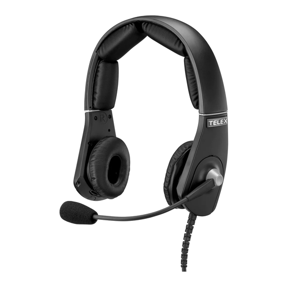
Page 11: Headset - Single-Sided
Single-Sided Headset Reference View FIGURE 14. Headset Adjustment Slider. For more information, see “Headset Adjustment and Sizing” on page 21. Headband Cushion Temple Pad Ear Cushion Windscreen Boom Mic Side Pads Bosch Security Systems, Inc. Technical Manual F.01U.196.221 Rev. 08... -
Page 12: Dual-Sided Headset Reference Diagram
ANR Switch (ANR equipped module only) NOTE: The switch label is used to determine the on and off position for ANR Battery Module/Filler Module Ear Cup Cushions Microphone Module Microphone Windscreen Side Pads Technical Manual Bosch Security Systems, Inc. F.01U.196.221 Rev. 08... -
Page 13: Filler Module
NOTE: The battery charger uses a universal power pack with a mini-USB connector. Alternative power packs may be used provided they are equipped with the mini-USB connector, for example a cell phone charger. Bosch Security Systems, Inc. Technical Manual F.01U.196.221... -
Page 14: Battery Charger Power Supply
Standard Power Supply and Plug Adapters FIGURE 18. Standard Power Supply Wall Pack US Plug (standard) World Power Supply Adapters (Optional - p/n PRD000253005) UK Plug (optional) Euro Plug (optional) Australian Plug (optional) Technical Manual Bosch Security Systems, Inc. F.01U.196.221 Rev. 08... -
Page 15: Configuration And Installation
Battery Charging For information on charging the battery, see “Charge the Battery” on page 32. Battery Installation For information on installing the battery, see “Remove and Replace Modules” on page 19. Technical Manual Bosch Security Systems, Inc. F.01U.196.221 Rev. 08... -
Page 16: Installation Instructions
Insert the Microphone plug into the microphone jack on the aircraft console. Insert the Headphone plug into the headphone jack on the aircraft console. For a detailed dual plug wiring diagram, see Figure 24 on page 35. Technical Manual Bosch Security Systems, Inc. F.01U.196.221 Rev. 08... -
Page 17: Audio Input Installation
Adjust the headset for proper fit and comfort. See “Headset Adjustment and Sizing” on page 21. Step 4 Turn on ANR (if equipped). See “Turn the ANR On/Off (ANR Capable Headset Only)” on page 23. Bosch Security Systems, Inc. Technical Manual F.01U.196.221... - Page 18 18 Configuration and Installation Ascend Technical Manual Bosch Security Systems, Inc. F.01U.196.221 Rev. 08...
-
Page 19: Operation And Maintenance
Do not use any sharp objects or tools to press the module release button. To remove a module, do the following: Press the module release button located at the bottom of the ear shell. The module pops up from the ear shell. Technical Manual Bosch Security Systems, Inc. F.01U.196.221 Rev. 08... - Page 20 To replace a module, do the following: Align the mounting tab with the mounting tab hole. Slide the module into place. Press down on the module, snapping it into the ear shell. Technical Manual Bosch Security Systems, Inc. F.01U.196.221 Rev. 08...
-
Page 21: Headset Adjustment And Sizing
With the headset resting securely on the top of the head, slide the ear shell up and down to center the ear cup over the ear. Swivel the ear shell left or right to position the ear cup straight on the ear. Bosch Security Systems, Inc. Technical Manual F.01U.196.221... -
Page 22: Boom Mic Adjustment
“Remove and Replace Modules” on page 19. For best clarity, place the boom mic as close to the mouth as possible and speak into the mic (see Figure 20). Boom Mic Movement FIGURE 20. Technical Manual Bosch Security Systems, Inc. F.01U.196.221 Rev. 08... -
Page 23: Turn The Anr On/Off (Anr Capable Headset Only)
To turn ANR off, do the following: On the left ear cup, move the ANR switch to the down position (indicated by 0 on the label). Remove battery to conserve battery power when not in use. Bosch Security Systems, Inc. Technical Manual F.01U.196.221... -
Page 24: Configure The Speaker Volume
Locate the dip switch window on the back of either the boom mic module or the listen only module. Dip Switch Settings NOTE: The two (2) right-most switches are used to configure speaker volume. Speaker Volume Dip Switch Settings TABLE 1. Dip Switch Description Intensified Volume Normal Volume Technical Manual Bosch Security Systems, Inc. F.01U.196.221 Rev. 08... -
Page 25: Set Mono Or Left Only Mode
Left Only Mode To configure mono or left only on the headset, do the following: > Using Table 2 on page 25, set the dip switches to the mode of operation desired. Bosch Security Systems, Inc. Technical Manual F.01U.196.221 Rev. 08... -
Page 26: Replace The Earcup And Headband Cushion
To replace the one-cushion version headband cushion, do the following: Grasp the headband cushion. Pull the old cushion off the headband. Align the new headband cushion (loop) to the headband loop material. Firmly press the new headband cushion in place. Technical Manual Bosch Security Systems, Inc. F.01U.196.221 Rev. 08... -
Page 27: Replace The Windscreen
Replace the Windscreen To replace the wind screen, do the following: Remove the existing windscreen from the boom mic and throw away. Gently push the new windscreen over the boom mic. Bosch Security Systems, Inc. Technical Manual F.01U.196.221 Rev. 08... -
Page 28: Adjust Microphone Gain
Insert a small, flathead screwdriver through the access hole in the boom mic module. Turn the gain pot clockwise to increase the gain. Turn the gain pot counterclockwise to decrease the gain. Technical Manual Bosch Security Systems, Inc. F.01U.196.221 Rev. 08... -
Page 29: Care And Maintenance
For storing or transporting your Ascend headset, use the protective carrying case the headset is shipped in. For placement of the headset in the carrying case, see Figure 22. Carrying Case FIGURE 22. Bosch Security Systems, Inc. Technical Manual F.01U.196.221 Rev. 08... - Page 30 30 Operation and Maintenance Ascend Technical Manual Bosch Security Systems, Inc. F.01U.196.221 Rev. 08...
-
Page 31: Battery Module
To replace a battery module, do the following: Align the mounting tab with the mounting tab hole. Slide the battery module into place. Press down on the battery module, snapping it into the ear shell. Technical Manual Bosch Security Systems, Inc. F.01U.196.221 Rev. 08... - Page 32 While pressing the adapter lock, turn the adapter counter-clockwise to release the adapter. Replace the current adapter with the desired power module adapter. Turn the new adapter clockwise to lock it in place. Technical Manual Bosch Security Systems, Inc. F.01U.196.221 Rev. 08...
- Page 33 Slide the battery module into place. Press down on the battery module, snapping it into the battery module. The LED lights red while the battery is charging, and lights green when it is finished charging. Bosch Security Systems, Inc. Technical Manual F.01U.196.221...
- Page 34 34 Battery Module Ascend Technical Manual Bosch Security Systems, Inc. F.01U.196.221 Rev. 08...
- Page 35 CHAPTER 5 Wiring Diagrams Dual Plug Wiring Diagram FIGURE 24. 5-Pin XLR (male) Wiring Diagram FIGURE 25. Technical Manual Bosch Security Systems, Inc. F.01U.196.221 Rev. 08...
- Page 36 36 Wiring Diagrams Ascend Music/Entertainment Module Connector Wiring Diagram FIGURE 26. Technical Manual Bosch Security Systems, Inc. F.01U.196.221 Rev. 08...
- Page 37 100Hz - 10kHz per DO-214 fig.2-1 Distortion <5% @ 114dB SPL, 350Hz - 6kHz Sensitivity -28 ±3dBV/Pa @1kHz Noise Level <1mV RMS Headset/handset Isolation <2mV at mic with 10mW to speaker Technical Manual Bosch Security Systems, Inc. F.01U.196.221 Rev. 08...
- Page 38 Power (green) Music Plug 3.5mm, 3 conductor plug Tip: Left (yellow) Ring: Right (red) Sleeve: Ground (black) Gross Weight 5 – 8 oz (no battery) Cord Length 1.8m (straight) Color Black Technical Manual Bosch Security Systems, Inc. F.01U.196.221 Rev. 08...
- Page 39 Home repair may void TSO requirements. How long will it take my headset to be repaired? Repair duration is usually 7 to 10 working days plus shipping time back to the customer. Technical Manual Bosch Security Systems, Inc. F.01U.196.221 Rev. 08...
- Page 40 Cord Module, No Microphone, PJ Connectors ........................... PRD000253012 Cord Module, No Microphone, XLR Connector......................... PRD000253013 Filler Module ....................................PRD000253014 Temple Pad ....................................PRD000253015 Carrying Case ....................................PRD000253016 Headband Pad, 3-piece ................................PRD000253017 Technical Manual Bosch Security Systems, Inc. F.01U.196.221 Rev. 08...
- Page 41 Ascend Troubleshooting and FAQs 41 Bosch Security Systems, Inc. Technical Manual F.01U.196.221 Rev. 08...
- Page 42 Bosch Security Systems, Inc. Telex Headsets Phone: 1.800.898.6723 (technical support) Email: repair.lincoln@us.bosch.com Website: www.telex.com/us/aviation/line...