Table of Contents
Advertisement
Available languages
Available languages
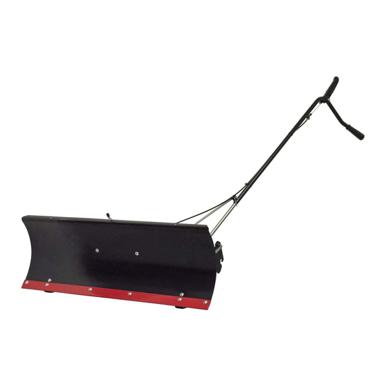
42" SNOW BLADE
RABOT-DÉNEIGEUR DE 42 PO
PALA DE NIEVE DE 42"
COMPATIBLE WITh:
cmXGram1130043
cmXGram1130044
cmXGram1130045
cmXGran1130047
If you have questIons or comments, contact us.
Pour toute questIon ou tout commentaIre, nous contacter.
sI tIene dudas o comentarIos, contáctenos.
1-888-331-4569
InstructIon Manual | GuIde d'utIlIsatIon | Manual de InstructIones
WWW.CRAFTSMAN.COM
CMXGZBF7124441
Advertisement
Table of Contents

Related Manuals for Craftsman CMXGZBF7124441

Summary of Contents for Craftsman CMXGZBF7124441
- Page 1 RABOT-DÉNEIGEUR DE 42 PO PALA DE NIEVE DE 42” COMPATIBLE WITh: cmXGram1130043 cmXGram1130044 cmXGram1130045 cmXGran1130047 CMXGZBF7124441 If you have questIons or comments, contact us. Pour toute questIon ou tout commentaIre, nous contacter. sI tIene dudas o comentarIos, contáctenos. 1-888-331-4569 WWW.CRAFTSMAN.COM...
- Page 2 English (original instructions) Français (traduction de la notice d’instructions originale) Español (traducido de las instrucciones originales) Definitions: Safety Alert Symbols and Words This instruction manual uses the following safety alert symbols and words to alert you to hazardous situations and your risk of personal injury or property damage.
- Page 3 EnglIsh CArtOn COntentS For model 917 tractors 27611 24023 63033 49808 27612 For model CMX/247 tractors 25647 48167 24520 27864 HArDWAre PACKAge COntentS (14) 43001 44326 47631 43350 48106 710-0305 43648 43085 44917 712-0256 43070 43081 47189 23658 (13) R19172410 47810 46071 (20)
- Page 4 Unneeded items may be discarded after assembly has been completed. MTD LLC nOTE: Right hand (RH) and Left hand (LH) are determined P.O. BOX 361131 www.Craftsman.com from the operator's position while seated on the tractor. CLEVELAND, OH 44136 PATENT www.OPEpatents.com...
- Page 5 EnglIsh inStrUCtiOnS fOr CmX mODeL trACtOrS Step 3: (fig. 3) Assemble a shoulder bolt (I) and a 3/8" nylock nut (M) Step 1: (fig. 1) to the front of the tractor frame on each side, unless a Attach an angle support bracket to the top holes in the shoulder bolt is already present.
- Page 6 EnglIsh inStrUCtiOnS fOr 917 mODeL trACtOrS Step 2: (fig. 7) 1. Fasten the R.H. Side Plate (bend facing out) to the front Step 1: (fig. 5) three holes in the tractor frame using thre 3/8" x 1" carriage bolts (H), three large 1/2" washers (N) (see note), and three lOCATE ThE MOWER sUsPEnsIOn BRACKETs 3/8"...
- Page 7 EnglIsh inStrUCtiOnS fOr tyPe A trACtOrS inStrUCtiOnS fOr tyPe b trACtOrS Step 1: (fig. 9) Step 1: (fig. 11) Remove any bolts found in the holes indicated in the Remove any bolts found in the holes indicated in the illustration. illustration.
- Page 8 EnglIsh inStrUCtiOnS fOr 917 mODeL trACtOrS inStrUCtiOnS fOr 247 mODeL trACtOrS Step 1: (fig. 13) Step 1: (fig. 15) Assemble one angle support bracket (16) to the Attach an angle support bracket (23) to the top holes in topmost set of holes in the hanger brackets using the quick attach brackets using two 3/8"...
- Page 9 EnglIsh Step 3: (fig. 17) Step 4: (fig. 18) Selet the illustration below which most closely Pull out on the attachment pins of the hitch assembly resembles your tractor. and swing the top of the pins down away from the holes they were in.
- Page 10 EnglIsh Step 2: (fig. 20) Step 4: (fig. 22) Insert the round hook end of the angle lock spring up Assemble a 3/8" x 1-1/4" carriage bolt (E) through the through the hole in the spring mount bracket. square hole in the Cable Mount Bracket and through the square hole in the angle lock bars.
- Page 11 EnglIsh Step 6: (fig. 24) Step 7: (fig. 25) Assemble ball end of control cable up through hole in To attach the blade to the channel assembly, align the cable end fitting and pull until ball slips insided curled notched holes in the pivot plate with the notched edge of fitting.
- Page 12 EnglIsh Step 8: (fig. 26) Step 10: (fig. 28) Assemble the large 1/2" washer (Q) onto the channel Remove the rubber cap and the first jam nut from the pivot pin (6). threaded end of the control cable and slide them onto the control cable wire.
- Page 13 EnglIsh Step 12: (fig. 30) Place the end of the blade pivot rod (19) down through the blade pivot shaft. Attach the other end of the blade pivot rod to the lift handle tube. Secure both ends with a hairpin cotter (W). The holes for the hairpin cotters should be parallel to the ground.
- Page 14 EnglIsh LIFT HANDLE TUBE LOCK RELEASE GRIP ASSEMBLY BLADE PIVOT ROD ANGLE LOCK BARS BLADE ADJUST SPRING LIFT HANDLE ROD BLADE SHOE CONTROL CABLE BLADE PIVOT SHAFT OPerAtiOn How to Use your Snow blade • Read this owner's manual and safety To Raise or lower the snow Blade: (Fig. 32) rules before operating your snow blade.
- Page 15 EnglIsh Using the snow Blade • Prepare the lawn tractor engine for cold weather using instructions furnished with the lawn tractor. • Always begin with the transmission in first (low) gear and gradually increase speed as required. • To reduce icing on the Blade, allow the lawn tractor and blade to adjust to outdoor temperature before operating.
- Page 16 EnglIsh SerViCe AnD ADJUStmentS StOrAge to Adjust blade Spring recommandations When Storing • The tension of the Blade Adjust Spring may be altered • When the Snow Blade is not being used, remove all to permit the Blade to tilt froward to bypass solid dirt and rust and touch up with paint.
- Page 17 Limited Warranty CRAFTSMAN® is a registered trademark of Stanley Black & Decker, Inc., used CRAFTSMAN will repair or replace, without charge, any under license. defects due to faulty materials or workmanship for three years from the date of purchase. This warranty does not es una marca registrada de Stanley Black &...
- Page 18 FRAnçAIs AVertiSSementS générAUX SUr LA inStrUCtiOnS POUr LeS trACteUrS SéCUrité DeS OUtiLS mODÈLe CmX AVeRtISSeMeNt : lisez tous les avertissements étape 1 : (fig. 1) de sécurité, toutes les instructions, les Fixer une équerre de fixation sur les trous supérieurs illustrations et les caractéristiques fournis des supports de fixation rapide avec deux boulons avec cet outil électrique.
- Page 19 FRAnçAIs inStrUCtiOnS POUr LeS trACteUrS inStrUCtiOnS POUr LeS trACteUrS mODÈLe 917 AVeC DeUX SUPPOrtS De SUSPenSiOn De PLAtefOrme AVAnt étape 1 : (fig. 5) étape 1 : (fig. 8) lOCAlIsATIOn DEs sUPPORTs DE sUsPEnsIOn DE TOnDEUsE 1. Comparer le tracteur utilisé à ceux illustrés à la figure 8. 1.
- Page 20 FRAnçAIs inStrUCtiOnS POUr LeS trACteUrS étape 3 : (fig. 17) mODÈLe 917 Sélectionner l’illustration ci-dessous qui ressemble le plus à votre tracteur. étape 1 : (fig. 13) Monter un boulon à épaulement (I) et un écrou nyloc de 9,5 mm (M) sur l’avant du châssis du tracteur de Fixer une équerre de fixation (16) sur le jeu de trous chaque côté, sauf si un boulon à...
- Page 21 FRAnçAIs étape 3 : (fig. 21) Enlever le capuchon en plastique et un écrou hexagonal de 9,5 mm du boulon dans le ressort de Avec un marteau, monter un écrou autofileteur de 9,5 réglage du rabot-déneigeur. Ajuster l’écrou hexagonal mm (S) sur une extrémité de la tige à ressort. Insérer de 9,5 mm en le descendant de 25 mm environ sur l’autre extrémité...
- Page 22 FRAnçAIs étape 11 : (fig. 29) fOnCtiOnnement Monter la prise en plastique sur la poignée de • Lire le présent manuel du propriétaire et verrouillage/déverrouillage. les consignes de sécurité avant d’utiliser Fixer la poignée de verrouillage/déverrouillage sur le rabot-déneigeur. Utiliser l’illustration le tube de la poignée de levage avec un boulon ci-dessous du rabot-déneigeur pour se hexagonal de 7,9 mm x 38 mm (C) et un écrou nyloc familiariser avec ses différentes commandes de 7,9 mm (L).
- Page 23 FRAnçAIs mode d’emploi du rabot-déneigeur entretien et AJUStementS Pour faire remonter ou abaisser le rabot- Pour ajuster le ressort du rabot-déneigeur déneigeur : (Fig. 32) • La tension du ressort de réglage du rabot-déneigeur peut être modifiée pour permettre l’inclinaison du •...
- Page 24 FRAnçAIs rAngement recommandations de rangement • Lorsque le rabot-déneigeur n’est pas utilisé, enlever toutes les saletés et la rouille et retoucher avec de la peinture. • Retoucher le métal nu avec de la peinture ou appliquer une fine pellicule de graisse ou d’antirouille. •...
- Page 25 EsPAÑOl inStrUCCiOneS PArA trACtOreS De advertencias de seguridad a ) Lea los manuales del tractor y la pala de nieve, y mODeLO CmX asegúrese de saber cómo operarlos antes de usar el Paso 1: (fig. 1) tractor con la pala de nieve. b ) Nunca opere el tractor ni la pala de nieve sin la Fije un soporte angular a los orificios superiores ropa adecuada para las condiciones climáticas y la...
- Page 26 EsPAÑOl inStrUCCiOneS PArA trACtOreS De inStrUCCiOneS PArA trACtOreS COn mODeLO 917 SOPOrteS De SUSPenSiÓn DeLAnterA De PLAtAfOrmA DObLeS Paso 1: (fig. 5) Paso 1: (fig. 8) BUsQUE lOs sOPORTEs DE sUsPEnsIÓn DE lA PODADORA 1. Compare su tractor con los que se muestran en la Figura 1.
- Page 27 EsPAÑOl inStrUCCiOneS PArA trACtOreS De Paso 3: (fig. 17) mODeLO 917 Seleccione la ilustración que se asemeje más a su tractor. Paso 1: (fig. 13) Coloque un perno de tope (I) y una tuerca mecánica de seguridad de 3/8” (M) en la parte delantera de cada Instale un soporte angular (16) al conjunto superior lado del bastidor del tractor, a menos que ya haya un de orificios en los soportes colgantes con dos pernos...
- Page 28 EsPAÑOl Paso 2: (fig. 20) Paso 6: (fig. 24) Inserte el extremo de enganche redondo del resorte de Pase el extremo de bola del cable de control a través bloqueo de ángulo a través del orificio en el soporte del orificio en la conexión del extremo del cable y tire de montaje de resorte.
- Page 29 EsPAÑOl Paso 9: (fig. 27) Paso 12: (fig. 30) Desde el lado izquierdo, pase el extremo soldado de Pase el extremo de la varilla pivotante de la pala (19) la varilla de la manivela de elevación a través del a través del eje pivotante de la pala. Fije el otro orificio en el extremo del conjunto del canal (Figura extremo de la varilla pivotante de la pala al tubo de 27).
- Page 30 EsPAÑOl OPerACiÓn Cómo usar su pala de nieve • Lea este manual del propietario y las reglas Para elevar o bajar la pala de nieve: (Fig. de seguridad antes de operar su pala de nieve. Compare la siguiente ilustración con su pala de nieve para familiarizarse con los • Use el mango que está ubicado en el extremo de la diversos controles y sus ubicaciones. manivela. Para elevar la pala, tire hacia atrás mientras presiona el mango de la manivela hacia abajo.
- Page 31 EsPAÑOl mAntenimientO y AJUSteS ALmACenAmientO Para ajustar el resorte de la pala recomendaciones para el almacenamiento • Se puede cambiar la tensión del resorte de ajuste de la pala para permitir que la pala se incline hacia • Cuando no se use la pala de nieve, elimine toda la adelante a fin de sortear obstáculos sólidos.
- Page 32 42" Snow Blade cmXgZBf7124441...
- Page 33 ref. pArt qtY. description ref. pArt qtY. description 23114 Blade 42" 43348 Angle Lock Spring 23117 Wear Plate 42" 746-0260 Cable End Fitting 62980 Reinforcement Plate 731-0869 Grip, Plastic Assembly 46471 Handle, Grip 43080 Bolt, Carriage 5/16-18 712-0256 Hex Jam Nut, 5/16-24 x 3/4"...
- Page 36 Stanley Black & Decker, Inc., used under license. es una marca registrada de Stanley Black & Decker, Inc., utilizada bajo licencia. est une marque déposée de Stanley Black & Decker, Inc., utilisée sous licence. © 2018 CRAFTSMAN Product Manufactured by: Producto fabricado por: Produit fabriqué...