Table of Contents
Advertisement
Quick Links
Advertisement
Table of Contents

Related Manuals for Brother BE-0901E-AC-PC

Summary of Contents for Brother BE-0901E-AC-PC
- Page 1 BE-0901E-AC-PC BE-1201B-AC-PC PC Control type Please read this manual before using the machine. Please keep this manual within easy reach for quick reference. NINE NEEDLE ONE HEAD EMBROIDERY MACHINE TWELVE NEEDLE ONE HEAD EMBROIDERY MACHINE INSTRUCTION MANUAL...
-
Page 3: Safety Instructions
Thank you very much for buying a BROTHER sewing machine. Before using your new machine, please read the safety instructions below and the explanations given in the instruction manual. With industrial sewing machines, it is normal to carry out work while positioned directly in front of moving parts such as the needle and thread take-up lever, and consequently there is always a danger of injury that can be caused by these parts. -
Page 4: Notes On Safety
Keep the ventilation openings of the sewing machine free from the accumulation of lint or dust. Contact your Brother dealer or a qualified electrician for any electrical work that may need to be done. The sewing machine weighs approximately 195 kg. - Page 5 If an error occurs in machine operation, or if abnormal noises or smells are noticed, immediately turn off the power switch. Then contact your nearest Brother dealer or a qualified technician. If the machine develops a problem, contact your nearest Brother dealer or a qualified technician.
-
Page 6: Maintenance And Inspection
Maintenance and inspection of the sewing machine should only be carried out by a qualified technician. Ask your Brother dealer or a qualified electrician to carry out any maintenance and inspection of the electrical system. Turn off the power switch and disconnect the... -
Page 7: Warning Labels
* The following warning labels appear on the sewing machine. Please follow the instructions on the labels at all times when using the machine. If the labels have been removed or are difficult to read, please contact your nearest Brother dealer. Never touch or push the... - Page 8 ! ! ! ! BE-1201B-AC-PC Finger guard ! ! ! ! BE-0901E-AC-PC Belt cover Guard cover Finger guard W1750 BE-0901E-AC-PC• BE-1201B-AC-PC...
-
Page 9: Before Starting Operation
Do not store floppy disks under direct sunlight. W1213Q Avoid contact with solvent or drink. W1215Q Use a commercially available cleaning disk to clean the head of the floppy disk drive periodically. W1217Q BE-0901E-AC-PC• BE-1201B-AC-PC W1210Q W1212Q W1214Q W1216Q W1218Q... - Page 10 To do so, slide the write-protect notch to open the slot as shown below. Slide the notch in this direction to prevent data loss or overwriting. Slide the notch in this direction to write data. BE-0901E-AC-PC• BE-1201B-AC-PC W1219Q...
-
Page 11: Procedure Of Reading This Manual
This manual explains two models: - BE-0901E-AC-PC - BE-1201B-AC-PC Explanation for individual model is provided by identifying the model name. Check the model before using the machine. The display is BE-0901E-AC-PC. Configuration of this manual This manual consists of the following chapters: Chapter 1... -
Page 12: Table Of Contents
2-5 Mounting of Cotton Stand ... 2-5 2-6 Lubrication to Needle Bar Case... 2-6 2-7 Connection of Personal Computer to Machines (for connecting 4 sets) ... 2-7 2-8 Connection of Power Supply ... 2-9 2-9 Installation of Software ... 2-11 3. - Page 13 Status Bar ...5-14 Back to Previous Status ...5-15 Undo ...5-15 Redo ...5-15 Editing...5-16 Rotate ...5-16 Horizontal Flip ...5-17 Vertical Flip ...5-17 Point Symmetry...5-17 Repeat ...5-17 Resize ...5-20 Delete Stitch...5-20 Insert or Delete Code ...5-21 Insert Lock Stitch...5-22 BE-0901E-AC-PC• BE-1201B-AC-PC Contents...
- Page 14 Background color... 6-18 Renaming Machine... 6-19 Viewing Machine Information... 6-20 Design Information... 6-20 Setting Window Display ... 6-20 Minimizing and Aligning Windows... 6-21 Language... 6-23 Copying Data to Other Machines... 6-23 Configuration ... 6-24 Upgrading the Machine Program ... 6-24 BE-0901E-AC-PC• BE-1201B-AC-PC...
- Page 15 Moving the Home Position ...6-54 Step-forward/Step-back...6-55 Entering in the Step-forward/Step-back Mode...6-55 Setting Step-forward/Back Distance or Timing ...6-56 Stepping Forward/Back ...6-57 Resuming Embroidering...6-58 Moving Embroidery Position ...6-59 Centering Pattern...6-60 Saving Data ...6-61 Save...6-61 Save As...6-61 Running Other Programs ...6-62 BE-0901E-AC-PC• BE-1201B-AC-PC Contents...
- Page 16 Thread Breakage Information in Pattern... 8-14 Output Information ... 8-15 Total Output Information ... 8-16 Recess Time Setting... 8-17 Save As CSV... 8-18 Printing Production Report... 8-19 Page Setup... 8-19 Print ... 8-19 Copying Report Data ... 8-20 BE-0901E-AC-PC• BE-1201B-AC-PC...
- Page 17 5. Thread Wiper Adjustment ...10-9 6. Adjusting the Belt Tension ...10-10 Chapter 11 Error code list Chapter 12 Troubleshooting Mechanical Section...12-2 Electrical Section ...12-4 Chapter 13 Connection and Installation of Optional Equipment 1. Attaching Bobbin Winder ...13-2 BE-0901E-AC-PC• BE-1201B-AC-PC Contents...
- Page 18 Contents BE-0901E-AC-PC• BE-1201B-AC-PC...
-
Page 19: Chapter 1 An Introduction Of Embroidery Machine
Chapter 1 An Introduction of Embroidery Machine... -
Page 20: Specifications
3.5 2HD floppy disk (the equivalent to Tajima format) 3.5 2DD floppy disk (Barudan FDR/FMC format) (embroidary data in Storage medium FDR35III/V format only) 3.5 2DD floppy disk (ZSK format) 3.5 floppy disk (brother ECS format) Thread trimming Automatic thread trimmer Needle thread breakage Needle thread breakage detector... - Page 21 Chapter 1 An Introduction of Embroidery Machine BE-0901E-AC-PC• BE-1201B-AC-PC...
-
Page 22: Software
2-1 Necessary Systems The following systems are needed for installing the software. • Personal computer with a CPU of Intel Pentium 166 MHz or above (Even if the software is operable under the environment less than the required specification, such a case is out of the scope of warranty.) -
Page 23: Configuration Of Software
This program allows editing of data on embroidering operation including scaling, rotation, color change, etc. (4) Production Report This program is for collecting data on actual embroidering operation and calculating output, etc. BE-0901E-AC-PC• BE-1201B-AC-PC Chapter 1 An Introduction of Embroidery Machine... -
Page 24: Notes On Use
The software is equipped with an on-line help function as an accessory. Click , then the icon of the desired item. A message is displayed to explain the meaning and usage of the item. Pressing the [F1] key brings up the help screen of the application for your reference. BE-0901E-AC-PC• BE-1201B-AC-PC... -
Page 25: Basic Operation Of Software
! ! ! ! Click Press the left button of the mouse once. "Click [xx]" means moving the white arrow pointer to "xx" and pressing the left button once. BE-0901E-AC-PC• BE-1201B-AC-PC Chapter 1 An Introduction of Embroidery Machine W1358Q W1359Q... - Page 26 "Double-click [xx]" means moving the white arrow pointer to "xx" and pressing the left button twice continuously. ! ! ! ! Drag Move the mouse while holding down the left button. Dragging is used for defining an area. BE-0901E-AC-PC• BE-1201B-AC-PC W1361Q W1362Q...
- Page 27 The vertical scroll bar can be used in the same way. ! ! ! ! Status bar This bar is for displaying a brief description of the selected command. Status bar BE-0901E-AC-PC• BE-1201B-AC-PC Chapter 1 An Introduction of Embroidery Machine Upward movement...
- Page 28 When the arrow pointer is moved to another menu while a list of commands is displayed, those of the latter menu are displayed. 1-10 W1364Q Dimmed commands cannot be used unless an appropriate item is selected. Depending on the model, some items cannot be used. Commands with a mark have sub menus. W1731 BE-0901E-AC-PC• BE-1201B-AC-PC...
-
Page 29: Chapter 2 Preparation Of Embroidery Machine
Chapter 2 Preparation of Embroidery Machine... -
Page 30: Names Of Machine Components
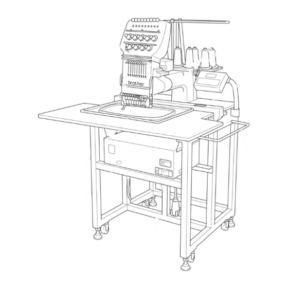
Chapter 2 Preparation of Embroidery Machine 1. Names of Machine Components ! ! ! ! BE-0901E-AC-PC Thread tension dial Thread take-up Inner thread guide Embroidery hoop Table Power switch Control box ! ! ! ! BE-1201B-AC-PC Pulley (A) Thread tension dial... -
Page 31: Installation
If the table is not stable, loosen nuts [2] and turn leveling seats [1] for adjustment. When relocating the machine, raise leveling seats [1]. The machine can then be moved with casters [3]. W1565 BE-0901E-AC-PC• BE-1201B-AC-PC Chapter 2 Preparation of Embroidery Machine... -
Page 32: Installation Of Operation Panel
Attach guard bar [1] to the machine. Fix it with bolts and washers from the lower side of the frame. Loosen thumb bolt [1]. Adjust the operation panel position for ease of use, and tighten thumb bolt [1]. W1653 BE-0901E-AC-PC• BE-1201B-AC-PC W1751... -
Page 33: Mounting Of Cotton Stand
2-5 Mounting of Cotton Stand ! ! ! ! BE-0901E-AC-PC ! ! ! ! BE-1201B-AC-PC Attach two thread guide support bars [2] to the cotton stand assembly [1], while fitting into the two holes. Mount the thread guide assembly [3] on the thread guide support bars [2] using the two screws [4]. -
Page 34: Lubrication To Needle Bar Case
(See the left figure.) Note)• Use the Brother's specified embroidery BE-0901E-AC-PC W1570 BE-1201B-AC-PC W1570 BE-0901E-AC-PC•... -
Page 35: Connection Of Personal Computer To Machines (For Connecting 4 Sets)
Turn off the power of the personal computer and the machine. Open the cover of the personal computer and insert an interface board included with the Machine Controller (option) into the slot for the PCI bus. Connect the interface board male connector and the personal computer RS-232C connector (COM1 or RS-232C-1) using the attached short RS cable included with the Machine Controller (option). - Page 36 The order of connecting four machines is arbitrary. • The maximum number of connecting machines is four. • A terminator should be connected to the connector SBUS2 of the lastly connected machine. Connection to SBUS1, 2 can be interchangeable. BE-0901E-AC-PC• BE-1201B-AC-PC (Terminator) W1656...
-
Page 37: Connection Of Power Supply
Use a cord plug that matches the receptacle type. When using a conversion plug, be sure to connect the grounding cable (green/yellow stripe) to the grounding terminal of the outlet. DANGER BE-0901E-AC-PC• BE-1201B-AC-PC Chapter 2 Preparation of Embroidery Machine Ground W1690... - Page 38 This unit is for protecting a personal computer from commercial power interruption, voltage drop, and external noise. Use of an uninterruptive power supply is strongly recommended. • This unit is not an attachment of the Brother's embroidery machine, and should be purchased separately from a different source. •...
-
Page 39: Installation Of Software
2-9 Installation of Software Use an attached CD-R for installing software. If a personal computer with no CD-R drive unit is used, connect a drive unit to the computer. Set the CD-R for installation. Setting the CD-R starts the installation program automatically. -
Page 40: Preparation For Embroidering
Turn off the power switch before starting preparation. Failure to do so may start the machine unintentionally through an accidental activation of the START switch, resulting in bodily injuries. 3-1 Upper Threading ! ! ! ! BE-0901E-AC-PC Thread guide tension disc Thread breakage pulley... - Page 41 Do not pass it through the presser foot. Pass it to needle bar thread guide at the front of lower thread guide [7]. Thread guide tension disc Spring Lower thread guide W1574 BE-0901E-AC-PC• BE-1201B-AC-PC Chapter 2 Preparation of Embroidery Machine W1575 2-13...
-
Page 42: Replacement Of Bobbin
W1578 Slide the thread under the tension spring [5] through the notch [4]. Pull out the thread from the hole of the tension spring [5]. Pull out the thread by about 50 mm. W1579 BE-0901E-AC-PC• BE-1201B-AC-PC Bobbin 0.5mm W1580... -
Page 43: Replacing And Selecting Needle
DB x K23 #11 because its rounded point prevents the knit thread from breaking. BE-0901E-AC-PC• BE-1201B-AC-PC Chapter 2 Preparation of Embroidery Machine part will come on the rotary hook side. • The needle eye should not be angled to the left (when viewed from the front). -
Page 44: Preparation Of Machine For Operation
BE-0901E-AC-PC• BE-1201B-AC-PC If thread take-up [1], which is not in the drive position, is out of alignment, raise it by hand. The stopper works to align thread take-up [1] with the others. - Page 45 Follow the steps below to fix this. ! ! ! ! BE-0901E-AC-PC ! ! ! ! BE-1201B-AC-PC Check if the needles stop in the normal position.
- Page 46 [6]. (The thread take-ups are aligned horizontally.) Note) W1589 W1590 BE-0901E-AC-PC• BE-1201B-AC-PC Check if the needle bars are lowered. If so, return them to the normal stop position. (Refer to "Normal needle stop position" on page 2-18.)
-
Page 47: Attachment Of Embroidery Hoop And Frame
If the material over the square frame is not set properly, stitches may be skipped, threads may be broken, or the material may shrink during embroidering. Make an adjustment using screw [6]. BE-0901E-AC-PC• BE-1201B-AC-PC Chapter 2 Preparation of Embroidery Machine... - Page 48 Remove screw [9] in Figure A. Position frame arms [8] R and L for the tubular round frame according to the mounting pitch of the tubular round frame, and attach the arms. Note) Attach the frame arms R and L symmetrically. 2-20 BE-0901E-AC-PC• BE-1201B-AC-PC Figure A Figure C W1592...
- Page 49 [3], spring washers [4], and plane washers [5] removed in step 2 Note) W1595 BE-0901E-AC-PC• BE-1201B-AC-PC Chapter 2 Preparation of Embroidery Machine Save the two screws, spring washers, and plane washers removed in the above step. They will be used later.
- Page 50 290 [9] to both vertical sides securely. Also attach two clips 220 [10] to both [10] horizontal sides securely. With a sash frame, the allowable embroidery area is 300 mm (vertical) x 450 mm (horizontal). W1657 BE-0901E-AC-PC• BE-1201B-AC-PC 300mm 450mm W1658...
-
Page 51: Adjustment Of Thread Tension
Upper the material and that the lower stitch width thread will be about 1/3 of the upper stitch width. Lower thread Lower stitch width W1662 6~8mm 0.07~0.12N W1663 BE-0901E-AC-PC• BE-1201B-AC-PC Chapter 2 Preparation of Embroidery Machine W1664 2-23... - Page 52 Note) W1665 W1666 BE-0901E-AC-PC• BE-1201B-AC-PC Check that the bobbin is pushed out of the bobbin case by about 0.5 mm. If not, the slip prevention spring of the bobbin case does not work. Adjust the spring in height or replace it with a new one.
-
Page 53: Chapter 3 Embroidering Procedures
Chapter 3 Embroidering Procedures After installation of machine and setting-up of the personal computer (PC), start embroidering. This chapter explains about the operation panel on the machine as well as precautions for the actual embroidering process. -
Page 54: Functions Of Operation Panel
Restarts after moving the carriage to embroidering start position by using the jog switch. Restarts embroidering after a suspension. Cancels errors during embroidering. Exits from the embroidering mode. Hold down this switch and press Suspends embroidering. Trims thread during suspension. W1667 BE-0901E-AC-PC• BE-1201B-AC-PC switch. - Page 55 When thread breakage or wiper out error has occurred, step-back or forward switch can be used to cancel errors. switches only.) switches only). is pressed while holding down B BE-0901E-AC-PC• BE-1201B-AC-PC Chapter 3 Embroidering Procedures switch simultaneously to stop during suspension. appears on the...
-
Page 56: Flowchart Of Preparation For Embroidering
Press on the operation panel. Register the machine name for initial start-up. (→ page 3-6) “Chapter 4 Selecting and Transferring Embroidery Data” (→ page 4-1) Edit the retrieved embroidery data. “Chapter 5 Editing Embroidery Data” (→ page 5-1) BE-0901E-AC-PC• BE-1201B-AC-PC... -
Page 57: Run The Software
Run the Software Select [Program] - [Brother Embroidery System] – [Ecsc] from the Start menu. The software starts up. Turn on the Machine Power Power switch W1596 Change the Flat / Cap hoop select switch according to the hoop to be used. -
Page 58: Register The Machine Name
Select an identifying color for the machine. This color is shown on the title bar for a while when the arrow pointer is moved to the title bar of a machine window. W1370Q after clicking the desired data. W1371Q W1363Q BE-0901E-AC-PC• BE-1201B-AC-PC... -
Page 59: Start Embroidering
Start Embroidering Check that the READY lamp on the machine operation panel is on. W1372Q Press to check the embroidering area. Press to start embroidering. B BE-0901E-AC-PC• BE-1201B-AC-PC Chapter 3 Embroidering Procedures... - Page 60 Chapter 3 Embroidering Procedures BE-0901E-AC-PC• BE-1201B-AC-PC...
-
Page 61: Chapter 4 Selecting And Transferring Embroidery Data
Chapter 4 Selecting and Transferring Embroidery Data Clicking on the machine controller brings up a screen which allows selecting or transference of registered embroidery data. Moving, copying, and deleting of embroidery data can also be carried out on this screen. -
Page 62: Functions (Command Reference)
Reads DOS format data. (→ page 4-16) Reads non-DOS format data. (→ page 4-18) Reads data in paper tape. (→ page 4-22) Converts ECS data to DST data. (→ page 4-25) Defines settings of data reading. (→ page 4-24) BE-0901E-AC-PC• BE-1201B-AC-PC... -
Page 63: Description Of Screen
Chapter 4 Selecting and Transferring Embroidery Data Sort by Stitches Sort by Name Sort by Colors Rename Sort by Date Delete Image List To display name and outline of the data registered in the selected directory BE-0901E-AC-PC• BE-1201B-AC-PC Information Help Tool bar Status bar W0964Q... -
Page 64: Creating A Directory
Click and select a parent directory in the window on the left. Select [New] - [Folder] from File menu. W0966Q Enter a new folder name. Click [OK]. A new directory is added to the window. W0965Q W0967Q W0968Q BE-0901E-AC-PC• BE-1201B-AC-PC... -
Page 65: Transferring Data
The explorer exits automatically after transferring the selected data. Transferring DST and DSB data Double click DST or DSB data or click the data and click The pattern image is displayed. To read the data, click [OK]. Chapter 4 Selecting and Transferring Embroidery Data W0969Q W0970Q BE-0901E-AC-PC• BE-1201B-AC-PC... - Page 66 If no image of embroidery data appears, select "Display Detail" on "Screen" of the control panel to adjust display color. Choose one of the following options, then restart PC. • 256 colors • High color (16 bits) • Full-color (24 bits) W0971Q Select the display color using "Color Pallet". W0972Q BE-0901E-AC-PC• BE-1201B-AC-PC...
-
Page 67: Copy
Drag data to destination directory while pressing [Ctrl] key. The pointer turns into Check that the copy destination directory is correct, then click [Yes]. W0974Q . Release the mouse button when the directory name is inverted. W0975Q W0976Q BE-0901E-AC-PC• BE-1201B-AC-PC Chapter 4 Selecting and Transferring Embroidery Data... -
Page 68: Moving Data
Click data for selection. Drag data to the destination directory. The arrow pointer turns into Check that the copy destination directory is correct, then click [Yes]. W0974Q . Release the mouse button when the directory name is inverted. W0978Q W0976Q BE-0901E-AC-PC• BE-1201B-AC-PC... -
Page 69: Deleting Data
Deleting Data Deletes embroidery data. Click data for selection. The frame of selected data becomes red. Select [Delete] from Edit menu or click W0979Q Click [Yes] to delete the selected data. Chapter 4 Selecting and Transferring Embroidery Data BE-0901E-AC-PC• BE-1201B-AC-PC... -
Page 70: Recreate An Icon
1. Click and select the data displayed as "Icon is not completed". The frame of the data selected is displayed in red. Select [Icon is made again.] from the Edit menu. The pattern image is displayed. Click [OK]. 4-10 W980Q W0970Q BE-0901E-AC-PC• BE-1201B-AC-PC... -
Page 71: Select All
Transfer to the machine controller is disabled. Select [Select all] from the Edit menu. The frame of the data selected is displayed in red. In the image display mode Chapter 4 Selecting and Transferring Embroidery Data In the text display mode W0981Q W0980Q BE-0901E-AC-PC• BE-1201B-AC-PC 4-11... -
Page 72: Renaming Data
! Upper and lower cases are not distinguished in the data name. Click data for selection. The frame of selected data turns red. Select [Rename] from Edit menu or click Enter a new data name. Enter a data name including extension. W0982Q Click [OK]. 4-12 extension BE-0901E-AC-PC• BE-1201B-AC-PC W0663Q... -
Page 73: Finding Data
Finding Data Retrieves and views embroidery data. Select [Find Files] from Tool menu. Enter the file name of embroidery data for search. Enter the file name correctly. Click [Find]. Chapter 4 Selecting and Transferring Embroidery Data W0983Q W0984Q BE-0901E-AC-PC• BE-1201B-AC-PC 4-13... - Page 74 Any number of wild characters can be used to replace other characters. ! Using "*" The wildcard character "*" represents a character or combination of characters. For instance, if "*.ecs" is entered to the file name box, the search will find all files with extension "ecs". 4-14 W0985Q BE-0901E-AC-PC• BE-1201B-AC-PC...
-
Page 75: Adjusting Screen Display
Sorts files by the number of colors in ascending order (in descending order). Sort by Date Sorts embroidery data by date in descending order (in ascending order). ! Updating to the latest information Displays the latest information. Select [Refresh] from View menu. Chapter 4 Selecting and Transferring Embroidery Data BE-0901E-AC-PC• BE-1201B-AC-PC 4-15... -
Page 76: Reading Data In Floppy Disk
• Non DOS format data Barudan FDR Barudan FMC Zanks ZSK Reading DOS Format Data Select [DST/DSB/DSZ → ECS Conversion] from Tool menu. Select data to read and click [Open]. The image of the selected pattern appears. 4-16 W0986Q W0970Q BE-0901E-AC-PC• BE-1201B-AC-PC... - Page 77 Set feed counts for thread breakage. Select the number of feeds or specify the feed length for trimming and click [OK]. Select the directory to save and name the file. Do not change extension ".ECS". Click [Save]. Chapter 4 Selecting and Transferring Embroidery Data W0971Q W0974Q BE-0901E-AC-PC• BE-1201B-AC-PC 4-17...
-
Page 78: Converting The Non Dos Format Data
Names, types, Numbers, sizes, number of stitches of FDR data are displayed. Names, sizes, number of stitches of FMC data are displayed. Names, Numbers, sizes, number of stitches of ZSK data are displayed. 4-18 When reading FDR data W0987Q When reading FMC data W0988Q When reading ZSK data W0989Q BE-0901E-AC-PC• BE-1201B-AC-PC... - Page 79 Set the floppy disk such as Barudan which is non-DOS format at the floppy disk drive of the PC. Select [Non DOS (Barudan, ZSK...) Conversion] from Tool menu. Chapter 4 Selecting and Transferring Embroidery Data W0990Q W0991Q BE-0901E-AC-PC• BE-1201B-AC-PC 4-19...
- Page 80 Chapter 4 Selecting and Transferring Embroidery Data Select data to read and click [OK]. The image of the selected pattern appears. To convert the selected data into ECS data. Click [OK]. 4-20 When "Details" is selected W0992Q When "Icon" is selected W0993Q W0994Q BE-0901E-AC-PC• BE-1201B-AC-PC...
- Page 81 Set feed counts for thread breakage. Select the number of feeds or specify the feed length for trimming and click [OK]. Select the directory to save the file and name the file. Do not change extension ".ECS". Click [Save]. Chapter 4 Selecting and Transferring Embroidery Data W1403Q W0995Q BE-0901E-AC-PC• BE-1201B-AC-PC 4-21...
-
Page 82: Reading Data In Paper Tape
Set paper tape after the LED of READ button light up. Select [Tape → ECS Conversion] from Tool menu. Select data format and click [OK]. The paper tape reader starts reading data. W0996Q 4-22 Power switch READ button Paper tape BE-0901E-AC-PC• BE-1201B-AC-PC W0414Q... - Page 83 The image of the selected pattern appears. Select the directory to save and name the file. Do not change extension ".ECS". Click [Save]. Chapter 4 Selecting and Transferring Embroidery Data W0970Q W0997Q BE-0901E-AC-PC• BE-1201B-AC-PC 4-23...
-
Page 84: Settings For Data Reading
Chapter 4 Selecting and Transferring Embroidery Data Settings for Data Reading Sets up the interface and data transfer speed of the paper tape reader or external disk drive. Select [Setup] from Tool menu. Select port and speed. Click [OK]. 4-24 W0998Q BE-0901E-AC-PC• BE-1201B-AC-PC... -
Page 85: Writing Data In Dst Format
Select the directory to save and name the file. Do not change extension ".dst". Click [Save]. Set feed counts for thread breakage. Select the count and click [OK]. Chapter 4 Selecting and Transferring Embroidery Data W0999Q W0971Q BE-0901E-AC-PC• BE-1201B-AC-PC 4-25... -
Page 86: Viewing Pattern Information
Version number of the file The number of stitches in embroidery data The number of colors used in embroidery data Size of masking Coordinates of embroidering start position Coordinates of embroidering end position Date of last revision of data BE-0901E-AC-PC• BE-1201B-AC-PC... -
Page 87: Chapter 5 Editing Embroidery Data
Chapter 5 Editing Embroidery Data Clicking of the machine controller brings up a screen which allows editing of embroidery data. This screen allows simple processing of embroi- dery data and display setting of display. -
Page 88: Functions (Command Reference)
Centers embroidery data. (→ page 5-6) Zooms in or out. (→ page 5-6) Displays the needle penetration positions. (→ page 5-8) Displays the start/end positions of embroidering. (→ page 5-8) Displays the code insertion position for trim and pause. (→ page 5-8) BE-0901E-AC-PC• BE-1201B-AC-PC... - Page 89 Displays the setting screen for needle bar and speed range. (→ page 5-9) Displays the pattern in thread color. (→ page 5-13) Shows/hides the tool bar. (→ page 5-14) Shows/hides the status bar. (→ page 5-14) BE-0901E-AC-PC• BE-1201B-AC-PC Chapter 5 Editing Embroidery Data...
-
Page 90: Description Of Screen
Display Range Save Zoom Out Open Zoom In Horizontal Flip Needle bar and Vertical Flip Speed Range Point Symmentry Thread Redo color Repeat Undo Rotate BE-0901E-AC-PC• BE-1201B-AC-PC Design Information About This Application Resize Help Print Tool bar Status bar W1000Q... -
Page 91: Opening Embroidery Data
Opening Embroidery Data This function is available with embroidery data editor. Select [Open] from File menu or click Double-click the data or click the data and W1001Q BE-0901E-AC-PC• BE-1201B-AC-PC Chapter 5 Editing Embroidery Data... -
Page 92: Setting Display
Displays the whole image to the size of the window. Zoom In Select [Zoom] - [Zoom In] from View menu or click Repeats zooming of the image by the number of clicks. Before selecting W1002Q W1002Q BE-0901E-AC-PC• BE-1201B-AC-PC After selecting W1003Q After selecting W1004Q... - Page 93 Drag and define the range to zoom in with the mouse. Before selecting Fit to window Select [Zoom] - [Fit to window] from View menu or click Before selecting W1004Q W1005Q W1005Q BE-0901E-AC-PC• BE-1201B-AC-PC Chapter 5 Editing Embroidery Data After selecting W1005Q After selecting W1006Q After selecting W1007Q...
-
Page 94: Needle Penetration
Displays the position of the trim code and the pause code. Trim is displayed by X and pause is displayed by Select [Trim and pause] from the View menu. W1008Q W1010Q → W1012Q BE-0901E-AC-PC• BE-1201B-AC-PC After selecting W1009Q After selecting W1011Q W1013Q... -
Page 95: Microstitch
Indicates the needle number and the color. Indicates the stitching order and the color. W1015Q Pause is set when the range shows S marking. BE-0901E-AC-PC• BE-1201B-AC-PC Chapter 5 Editing Embroidery Data Microstitch After selecting W1016Q Indicates the range of each needle bar. - Page 96 Double click the desired embroidering sequence to change the color. 5-10 Refer to steps 1 and 2. Refer to steps 1 and 3. Refer to steps 1 and 3. Refer to steps 1 to 7. W1017Q W0699Q BE-0901E-AC-PC• BE-1201B-AC-PC...
- Page 97 When selecting a color from a color sample, click maker name or [User] and double click [Color]. When finely adjusting the selected color, click [Medium color]. Click [User] to crate a new color, then click [Addition]. The needle bar number can be changed. W1018Q W1019Q W1020Q BE-0901E-AC-PC• BE-1201B-AC-PC Chapter 5 Editing Embroidery Data 5-11...
- Page 98 Select a color by clicking on the color chart or by inputting a value, and click [OK]. Input the name of the color and click [OK] when [User] is selected in step 4. 5-12 Drag here to adjust brightness. To display data of the selected color. W1022Q W1023Q BE-0901E-AC-PC• BE-1201B-AC-PC...
-
Page 99: Thread Color
Select [Thread color] from the View menu or click Before selecting Dragged embroidering sequence Click here to put a check mark for pause before starting the designated embroidering sequence. W1025Q W1026Q BE-0901E-AC-PC• BE-1201B-AC-PC Chapter 5 Editing Embroidery Data After selecting W1027Q 5-13... -
Page 100: Tool Bar
Before selecting Status Bar Shows/hides the tool status. The status bar provides information on the current status and advice for operation. Select [Status Bar] from View menu. Before selecting 5-14 W1028Q W1030Q BE-0901E-AC-PC• BE-1201B-AC-PC After selecting W1029Q After selecting W1029Q... -
Page 101: Back To Previous Status
Select [Undo] from the Edit menu or click Redo Repeats the canceled step of "Undo". ! The screen can return to 3 steps maximum. Select [Redo] from the Edit menu or click BE-0901E-AC-PC• BE-1201B-AC-PC Chapter 5 Editing Embroidery Data 5-15... -
Page 102: Editing
If [Free] is selected, specify the angle. The value can be directly entered. Click [OK]. 5-16 W0558Q When the patterns are not grouped W0713Q To select angle. Click here to increase/decrease the value. BE-0901E-AC-PC• BE-1201B-AC-PC When they are not W0714Q W1032Q... -
Page 103: Horizontal Flip
Flips the image 180 degrees to the center position of the image. W0450Q Select [Point Symmetry] from Edit menu or click Repeat Repeats copying of the image by the specified number. W0450Q BE-0901E-AC-PC• BE-1201B-AC-PC Chapter 5 Editing Embroidery Data W0459Q W0460Q W608Q W0464Q... - Page 104 From top left, left to right direction From bottom left, left to right direction The value can be directly entered. Click here to increase/decrease the value. BE-0901E-AC-PC• BE-1201B-AC-PC W0717Q W0719Q Select the direction of repetition. Sets margins of the sewing area used for the calculation of the repetition number in the automatic setting.
- Page 105 Set the vertical and horizontal margin for sewing area. Click [OK]. Click [OK]. W1034Q Repetition number in horizontal direction. Repetition number in vertical direction. Numbers are up and down if clicked. Numbers can be directly input. W1035Q BE-0901E-AC-PC• BE-1201B-AC-PC Chapter 5 Editing Embroidery Data 5-19...
-
Page 106: Resize
0.0 to 1.0 mm in units of 0.1 mm. Select [Stitch deletion] from Edit menu. Designate the length of the stitch to be deleted. Click [OK]. Deleted result is displayed. Click [OK]. 5-20 Click here to increase/decrease the value. W1037Q W1038Q BE-0901E-AC-PC• BE-1201B-AC-PC W1395Q W1036Q... -
Page 107: Insert Or Delete Code
Insert (or delete) the pause code at the current needle position. Insert (or delete) the change color code at the current needle position. . Modified setting is saved. BE-0901E-AC-PC• BE-1201B-AC-PC Chapter 5 Editing Embroidery Data Insert (delete) change color code... -
Page 108: Insert Lock Stitch
If the lock stitch can be inserted, click [Yes]. W1041Q 5-22 Method of lock stitch Insert 3 stitches of 0.3 mm stitch. Insert 2 stitches of 0.3 mm stitch. Insert 1 stitch of 0.3 mm stitch. Do not insert the lock stitch. W1040Q BE-0901E-AC-PC• BE-1201B-AC-PC... -
Page 109: Changing Data
Starts embroidering at the specified position. Starts embroidering at the position clicked with the mouse. Cancels the specified position. Middle top edge Middle bottom edge Center W1042Q BE-0901E-AC-PC• BE-1201B-AC-PC Chapter 5 Editing Embroidery Data Upper right corner Middle right corner Lower right corner... -
Page 110: Changing End
Ends embroidering at the specified position. Ends embroidering at the position clicked with the mouse. Ends embroidering at the end position. Cancels the specified position. Middle top edge Middle bottom edge Center W1043Q BE-0901E-AC-PC• BE-1201B-AC-PC Upper right corner Middle right corner Lower right corner W0729Q... -
Page 111: Mask
Select [Mask] from Change menu. Select automatic or manual mode. If [Automatic] is selected, a mask is created automatically. If [Manual] is selected, drag the area with the mouse to specify the mask. W1044Q BE-0901E-AC-PC• BE-1201B-AC-PC Chapter 5 Editing Embroidery Data In this case, set 5-25... -
Page 112: Group
When the patterns are not grouped • The pattern is displayed only in the original copy source. Figures in other masks represent the embroidering sequence. • Each pattern in the mask rotates individually. (→ page 5-16) 5-26 W1045Q W1046Q BE-0901E-AC-PC• BE-1201B-AC-PC... -
Page 113: Setting Group For Repetition
Setting Group for Repetition Select [Repeat] in the Edit menu or click Click the checkbox of [Group] to put a check mark. Selecting from Menu Select [Group] from Change menu. W1033Q W1047Q BE-0901E-AC-PC• BE-1201B-AC-PC Chapter 5 Editing Embroidery Data 5-27... -
Page 114: Merge
! If the pattern to be merged is non-grouped repetition data, it is merged to each pattern. If the pattern does not fit the mask, the mask is automatically adjusted. Select [Merge] from the File menu. Select the pattern to be merged. 5-28 → W1048Q → W1050Q W1052Q BE-0901E-AC-PC• BE-1201B-AC-PC W1049Q W1051Q... - Page 115 Move the mouse while pressing the shift key. The mask moves horizontally and vertically. If the position is acceptable, click [Yes]. When [No] is clicked, repeat the steps from 3. The pattern is merged. W1053Q W1054Q W1055Q BE-0901E-AC-PC• BE-1201B-AC-PC Chapter 5 Editing Embroidery Data 5-29...
-
Page 116: Saving Data
If the edited data is larger than the mask, choose whether to carry out automatic masking or not. To save mask without changing To set and save mask automatically If color etc. has been is changed, the pattern image appears. W1057Q 5-30 To cancel saving W1056Q BE-0901E-AC-PC• BE-1201B-AC-PC... -
Page 117: Save As
If the edited data is larger than the mask, choose whether to carry out automatic masking or not. To save mask without changing To set and save mask automatically If color etc. has been is changed, the pattern image appears. W1057Q W1058Q To cancel saving W1059Q BE-0901E-AC-PC• BE-1201B-AC-PC Chapter 5 Editing Embroidery Data 5-31... -
Page 118: Viewing Pattern Information
Select [Design Information] from Help menu or click After checking, click [OK]. 5-32 The number of stitches in embroidery data The number of colors used in embroidery data Size of masking Coordinates of embroidering start position Coordinates of embroidering end position BE-0901E-AC-PC• BE-1201B-AC-PC... -
Page 119: Printing Data
Printing Data Prints data in editing. Select [Print] from File menu or click Specify the number of copies and other conditions. Click [OK]. BE-0901E-AC-PC• BE-1201B-AC-PC Chapter 5 Editing Embroidery Data 5-33... - Page 120 Chapter 5 Editing Embroidery Data BE-0901E-AC-PC• BE-1201B-AC-PC 5-34...
-
Page 121: Chapter 6 Embroidering
Chapter 6 Embroidering The PC controls the machine operation as well as settings of the machine. Note that the menu which appears on the screen depends on whether the power to the machine is turned on or off. -
Page 122: Functions (Command Reference)
(→ page 6-7) Changes display language. (→ page 6-8) Minimizes the size of display screen on the machine. (→ page 6-21) Renames the machine. (→ page 6-19) Displays machine information. (→ page 6-20) Exits from the machine controller. BE-0901E-AC-PC• BE-1201B-AC-PC... - Page 123 Runs the embroidery data editor. (→ page 6-62) Runs the embroidery data explorer. (→ page 6-62) Copies embroidery data to other machines. (→ page 6-23) Sets configuration for embroidering. (→ page 6-24) Upgrades the version of the machine parts. (→ page 6-24) BE-0901E-AC-PC• BE-1201B-AC-PC Chapter 6 Embroidering...
- Page 124 Shows the contents of settings. (→ page 6-43) Loads the setting details. (→ page 6-45) Saves the changed setting. (→ page 6-46) Selects the hoop type. (→ page 6-47) Cascades windows. (→ page 6-20) Tiles windows. (→ page 6-20) Align icons. (→ page 6-22) BE-0901E-AC-PC• BE-1201B-AC-PC...
-
Page 125: Description Of Screen
Whole pattern Step-back/step-forward Fit to window Move pattern Zoom in specified range Information Zoom out About This Application Zoom in Help Tool bar Open explorer Open editor Copy data to other machine Start embroidering Suspend embroidering Status bar W1060Q BE-0901E-AC-PC• BE-1201B-AC-PC... -
Page 126: Settings Before Turning On The Machine
Main menu items are displayed on this tool bar. Step Back This tool bar appears during step-back/forward. Select [Tool Bar] from View menu and put the check mark. Click here again to remove the check mark. Then the tool bar disappears. W1061Q BE-0901E-AC-PC• BE-1201B-AC-PC... -
Page 127: Displaying The Status Bar
This function is protected by a password. A dealer engineer will use this function if required. Communication Port Sets communication port between PC and machine. Select [Communication Port] from Configuration menu. Select communication port for use. Click [OK]. If the required port name does not appear, key-in the name. W1063Q BE-0901E-AC-PC• BE-1201B-AC-PC Chapter 6 Embroidering... -
Page 128: Language
When "Each respective language" is selected, the list for "Available Languages" may not be displayed properly. Click [OK]. Exit and rerun the software. Displays English. Displays the system language of PC. Displays the local language. Select display language among "Available Languages". W1640 BE-0901E-AC-PC• BE-1201B-AC-PC... -
Page 129: Settings After Turning Power On
Zoom Out Reduces the image to 80%. Select [Zoom Out] from Display menu or click Repeats zooming of the image by the number of clicks. Before selecting After selecting W1065Q After selecting W1065Q BE-0901E-AC-PC• BE-1201B-AC-PC Chapter 6 Embroidering W1066Q W1067Q... -
Page 130: Zoom In Specified Range
Select [Fit to Window] from View menu or click Before selecting Whole Pattern Displays the whole pattern. Select [Whole Pattern] from View menu or click Before selecting 6-10 After selecting W1065Q After selecting W1069Q After selecting W1065Q BE-0901E-AC-PC• BE-1201B-AC-PC W1068Q W1065Q W1070Q... -
Page 131: Grid
Select [Hoop position] from the View menu. The hoop view position is stored in the hoop data. If you reinstall the program, the hoop view position is initialized because it is overwritten. After selecting W1071Q After selecting W1073Q BE-0901E-AC-PC• BE-1201B-AC-PC Chapter 6 Embroidering W1072Q W1074Q 6-11... -
Page 132: Needle Penetration
Chooses whether or not the needle penetration positions are displayed. Clicking also provides the same function. Select [Needle Penetration] from View menu and put the check mark. Before selecting 6-12 W1075Q After selecting W1076Q After selecting W1078Q BE-0901E-AC-PC• BE-1201B-AC-PC W1077Q W1079Q... -
Page 133: Thread Color
Setting Needle Bar Needle bar allocation and display color can be changed on this screen. To display needle bar number and color After selecting W1071Q To display embroidering sequence and color BE-0901E-AC-PC• BE-1201B-AC-PC Chapter 6 Embroidering also provides the W1080Q W1082Q 6-13... - Page 134 Double-click the thread spool or needle bar number. 6-14 Refer to steps 1 and 2. Refer to steps 1 and 3. Refer to steps 1 and 3. Refer to steps 1 to 7. W1017Q BE-0901E-AC-PC• BE-1201B-AC-PC W1082Q...
- Page 135 When selecting a color from a color sample, click maker name or [User] and double click [Color]. When finely adjusting the selected color, click [Medium color]. Click [User] to crate a new color, then click [Addition]. The needle bar number can be changed. W1018Q W1019Q W1020Q BE-0901E-AC-PC• BE-1201B-AC-PC Chapter 6 Embroidering 6-15...
- Page 136 Input the name of the color and click [OK] when [User] is selected in step 4. Changing needle bar allocation Drag a thread spool to the desired needle bar number. This thread spool has been dragged 6-16 Drag here to adjust brightness. Displays data of the selected color W1022Q W1023Q W1084Q BE-0901E-AC-PC• BE-1201B-AC-PC...
-
Page 137: Setting Ranges
Click a speed range for selection. Click [OK]. Displays each thread bar range. When "S" is shown, it is under suspension. W1086Q Click here to put a check mark for pause before starting the designated embroidering sequence. BE-0901E-AC-PC• BE-1201B-AC-PC Chapter 6 Embroidering W1085Q W1087Q 6-17... -
Page 138: Grid Setting
Click the [color] to change the grid color. For setting, refer to steps 5 to 7 in page 6-16. Background color Changes the background color of the data. Select [Background color] from the [View] menu. W1090Q 6-18 Click this to increase or decrease the value. W1089Q BE-0901E-AC-PC• BE-1201B-AC-PC... -
Page 139: Renaming Machine
Select an identifying color for the machine. This color is shown on the title bar for a while when the arrow pointer is moved to the title bar of a machine window. BE-0901E-AC-PC• BE-1201B-AC-PC Chapter 6 Embroidering W1092Q W1093Q 6-19... -
Page 140: Viewing Machine Information
Windows are tiled. 6-20 W1094Q File name and path of embroidery data The number of stitches in embroidery data The number of colors used in embroidery data Size of masking Coordinates of embroidering start position Coordinates of embroidering end position BE-0901E-AC-PC• BE-1201B-AC-PC... -
Page 141: Minimizing And Aligning Windows
Minimize Window Size Select [Minimize Window Size] from Machine menu or click screen. Click here. W1098Q The window is minimized. When [Tile] is selected W1096Q W1099Q BE-0901E-AC-PC• BE-1201B-AC-PC Chapter 6 Embroidering W1097Q on the upper right corner of the 6-21... - Page 142 If this button is clicked, the window changes to the full size of the desktop. This button is used to end the software or to close the folder. clicked when the machine window is displayed. 6-22 W1100Q W1101Q BE-0901E-AC-PC• BE-1201B-AC-PC This button cannot be...
-
Page 143: Language
When multiple machines are connected, the embroidery data of a machine can be copied to another machine. Click the window of the machine displaying the copy source data. Click W1103Q Click and select the machine name of the destination. W1102Q W1104Q BE-0901E-AC-PC• BE-1201B-AC-PC Chapter 6 Embroidering 6-23... -
Page 144: Configuration
Upgrading the Machine Program Upgrades the programs at each part of the machine. This function is protected by a password. A dealer engineer will use this function if required. 6-24 W1105Q W1106Q Click here to the default setting. W1107Q BE-0901E-AC-PC• BE-1201B-AC-PC... -
Page 145: Setting The Machine
Click the needle number for selection. Click [OK]. The embroidering sequence appears at all specified needle points. Default setting (equating the sewing order number and needle bar number) Select [Needle] - [Default value] from Settings menu. W1108Q W1109Q BE-0901E-AC-PC• BE-1201B-AC-PC Chapter 6 Embroidering 6-25... -
Page 146: Same Speed Range
Sets whether to stop the needle bars temporarily when changing all the needle bars. Stopping all the needle bars temporarily Select [Pause] - [Add all] from Settings menu. Resetting temporary stop of all the needle bars Select [Pause] - [Delete all] from Settings menu. 6-26 W1111Q BE-0901E-AC-PC• BE-1201B-AC-PC... -
Page 147: Speed Range
Select [Speed Range] from Settings menu. Specify the desired range. When a value exceeding the above ranges is entered, it is automatically set to the min. or max. speed. Click [OK]. Indicates ranges of the current setting. W1641 BE-0901E-AC-PC• BE-1201B-AC-PC Chapter 6 Embroidering 6-27... -
Page 148: Hoop Feed Position
[Embroidery hoop] and the frame is displayed on the screen. Select [Hoop Feed Position] from Settings menu. Click the point to feed the hoop. The gray cross appears and shows the hoop feed position. 6-28 Hood feed position W1114Q W1115Q BE-0901E-AC-PC• BE-1201B-AC-PC... -
Page 149: Embroidery Area
The type of specified embroidery hoop changes the display. ! The kind of the selectable frame varies according to settings at machine side. ! The following selections are available: Tubular Flat Border Wide cap Semi-wide cap Baseball cap W1116Q BE-0901E-AC-PC• BE-1201B-AC-PC Chapter 6 Embroidering 6-29... - Page 150 ! The following shows the screen example with the frame selected. When “Tubular (ALL)” is selected. When “Wide cap (ALL)” is selected. 6-30 W1732 W1118Q The image is displayed upside down. The speed is automatically adjusted to 800 rpm or less. W1119Q BE-0901E-AC-PC• BE-1201B-AC-PC...
-
Page 151: Thread Trimming
The speed is automatically adjusted to 800 rpm or less. W1120Q For mm 0 - 100 mm (The standard value is 15 mm.) For inch 0 - 3.9 inch (The standard value is 0.6 inch.) W1121Q BE-0901E-AC-PC• BE-1201B-AC-PC Chapter 6 Embroidering 6-31... -
Page 152: Boring
! If editing such as reduction/enlargement and rotation is applied to embroidering data that has been created for boring, embroidering may not be performed correctly. Select [Boring] from Settings menu. W1733 Set the boring, shift, and range of needle bar. 3. Click [OK]. 6-32 W1734 BE-0901E-AC-PC• BE-1201B-AC-PC... -
Page 153: Thread Breakage Sensor
Adjust the sensor sensitivity. Click [OK]. The smaller the value is, the higher the W1642 The sensor sensitivity for each needle bar is adjusted individually. All sensor sensitivities for all needle bars are adjusted simultaneously. W1643 BE-0901E-AC-PC• BE-1201B-AC-PC Chapter 6 Embroidering 6-33... -
Page 154: Automatic Step Back
Select [Automatic Hoop Feed] from Settings menu and put the check mark ( ). W1752 6-34 Click here, and the value decreases/increases. Click here to give additional step-back for the sensing distance with the thread breakage sensor. W1127Q BE-0901E-AC-PC• BE-1201B-AC-PC... -
Page 155: End Of Embroidery
Sets if the machine returns to the start point after end of embroidery. Select [End of embroidery] from Settings menu. W1753 Click the checkbox to put a check mark ( ) when the machine returns to the start point after end of embroidery. Click [OK]. W1130Q BE-0901E-AC-PC• BE-1201B-AC-PC Chapter 6 Embroidering 6-35... -
Page 156: Mending
Chapter 6 Embroidering Mending Sets the details of mending. ! Items and descriptions are as follows: Automatically reset breakage error Error is automatically canceled when a thread breakage occurs. Select [Mending] from Settings menu. W1735 BE-0901E-AC-PC• BE-1201B-AC-PC 6-36... -
Page 157: Adjust
! For sewing to be close to a hoop, if the adjustment value is set too large, “Area Over” may occur while sewing and the operation may stop. Select [Adjust] from Settings menu. W1737 When setting is complete, click [OK]. W1134Q Cannot be set. W1132Q BE-0901E-AC-PC• BE-1201B-AC-PC Chapter 6 Embroidering 6-37... -
Page 158: Driving Shaft
Select [Activate escape with pause] from Settings menu and check it. For enabling escape, set pause for the needle bar. Refer to page 6-17 "Setting Ranges". W1740 6-38 Click to put a check mark ( for speeding up at the loading. Cannot be set. W1739 BE-0901E-AC-PC• BE-1201B-AC-PC... -
Page 159: Short Stitch Speed Reduction
! The speed can be set between 400 rpm and the maximum speed of the current hoop in units of 10 rpm. Select [Short stitch speed reduction] from Settings menu. W1741 Click [Reducing speed] to check it and click [OK] when items are set. W1647 BE-0901E-AC-PC• BE-1201B-AC-PC Chapter 6 Embroidering 6-39... -
Page 160: Thin / Thick Material
Select [Thin / Thick material] from Settings menu. W1742 Select thick or thin by moving the slide bar control. Click [OK] when it is set. 6-40 Clicking this button will set to thin / range: 1 / jog moving power up: no. W1757 BE-0901E-AC-PC• BE-1201B-AC-PC... -
Page 161: Area Trace
Select the outside shape of area tracing before starting sewing. ! The following two types can be selected. The selected outside shape is displayed on the screen. Rectangle Octagon W1142Q W1143Q Select the outside shape of [Area trace] from Settings menu and check it. W1744 BE-0901E-AC-PC• BE-1201B-AC-PC 6-41... -
Page 162: Default Settings
Not affected by the thread breakage sensor sensitivity Automatically rest breakage error 0.0 mm for X direction 0.0 mm for Y direction Activating speed up of driving shaft Thin Feed speed Jog moving power up "4 corner" is selected. BE-0901E-AC-PC• BE-1201B-AC-PC 15 mm (0.6 inch) -
Page 163: Show Setting
• Embroidery area • Enable inching • Hoop movement after thread trimming • Sensitivity • Backward steps • Automatic hoop feed • Return to the stant point • Activating speed up of driving shaft BE-0901E-AC-PC• BE-1201B-AC-PC Chapter 6 Embroidering 6-43... - Page 164 Chapter 6 Embroidering Select [Show Setting] from Settings menu. W1746 After checking, check [OK]. 6-44 W1648 BE-0901E-AC-PC• BE-1201B-AC-PC...
-
Page 165: Load Setting
Load Setting Load the setting. ! The set file has an extension of "ecm". Select [Load setting] from Settings menu. W1754 Select the folder and click [Open]. W1150Q BE-0901E-AC-PC• BE-1201B-AC-PC Chapter 6 Embroidering 6-45... -
Page 166: Save Setting
Save Setting Saves the edit settings. ! Save the setting files with an extension of "ecm". Change the setting. Select [Save setting] from Settings menu. W1755 Select the registration folder and put a file name. Click [Save]. 6-46 W1152Q BE-0901E-AC-PC• BE-1201B-AC-PC... -
Page 167: Load Hoop
◎SQUARE_FRAME24X24.ehp SQUARE_FRAME45X27.ehp Spider net frame SPIDER_NET_FRAME05B-1.ehp SPIDER_NET_FRAME05B-3.ehp SPIDER_NET_FRAME07B-1.ehp SPIDER_NET_FRAME07B-3.ehp SPIDER_NET_FRAME07T-1.ehp ROUND_FRAME25.ehp W0839Q SQUARE_FRAME45X23.ehp W0841Q SQUARE_FRAME45X32.ehp W1693 SPIDER_NET_FRAME05B-2.ehp W0845Q SPIDER_NET_FRAME05B-4.ehp W1696 SPIDER_NET_FRAME07B-2.ehp W0853Q SPIDER_NET_FRAME07B-4.ehp W1699 SPIDER_NET_FRAME07T-2.ehp W0849Q BE-0901E-AC-PC• BE-1201B-AC-PC Chapter 6 Embroidering W0840Q W1692 W1694 W1695 W1697 W1698 W1700 W1701 6-47... - Page 168 W1702 SPIDER_NET_FRAME09T-2.ehp W0857Q SPIDER_NET_FRAME09T-4.ehp W1705 SPIDER_NET_FRAME10B-2.ehp W0861Q SPIDER_NET_FRAME10B-4.ehp W1708 SPIDER_NET_FRAME12T-2.ehp W0865Q SPIDER_NET_FRAME12T-4.ehp W1711 SPIDER_NET_FRAME13B-2.ehp W0869Q SPIDER_NET_FRAME13B-4.ehp W1714 SPIDER_NET_FRAME15T-2.ehp W0873Q SPIDER_NET_FRAME15T-4.ehp W1717 SPIDER_NET_FRAME16B-2.ehp W0877Q SPIDER_NET_FRAME16B-4.ehp W1720 BE-0901E-AC-PC• BE-1201B-AC-PC W1703 W1704 W1706 W1707 W1709 W1710 W1712 W1713 W1715 W1716 W1718 W1719 W1721...
- Page 169 TUBULAR_FRAME40X43.ehp Holder base frame HOLDER_BASE23X24.ehp SPIDER_NET_FRAME18T-2.ehp W0881Q SPIDER_NET_FRAME18T-4.ehp W1723 W0885Q ◎TUBULAR_FRAME-07.ehp W0886Q ◎TUBULAR_FRAME-13.ehp W1549Q ◎TUBULAR_FRAME-19.ehp W0890Q TUBULAR_FRAME23X43.ehp W0892Q TUBULAR_FRAME30X28.ehp W1725 ◎TUBULAR_FRAME30X48.ehp W1553Q W1554Q HOLDER_BASE23X43.ehp W0899Q BE-0901E-AC-PC• BE-1201B-AC-PC Chapter 6 Embroidering W1722 W1724 W0887Q W1550Q W0891Q W0893Q W1551Q W1726 W0900Q 6-49...
- Page 170 ◎TUBULAR_ROUND12.ehp ◎TUBULAR_ROUND18.ehp ◎TUBULAR_ROUND24X30.ehp ◎TUBULAR_ROUND32X45.ehp Cap frame semi-wide frame ◎CAP_FRAME_SEMI_WIDE.ehp Cap frame wide frame ◎CAP_FRAME_WIDE.ehp 6-50 HOLDER_BASE30X43.ehp W0901Q HOLDER_BASE40X43.ehp W1727 ◎TUBULAR_ROUND09.ehp W0905Q ◎TUBULAR_ROUND15.ehp W0907Q ◎TUBULAR_ROUND24X24.ehp W0909Q TUBULAR_ROUND30X30.ehp W0911Q ◎TUBULAR_ROUND335X453.ehp W0913Q W0915Q W0916Q BE-0901E-AC-PC• BE-1201B-AC-PC W0902Q W1728 W0906Q W0908Q W0910Q W1729 W1730...
- Page 171 Select [Load hoop] from Settings menu. W1749 Select the folder and click [Open]. W1154Q BE-0901E-AC-PC• BE-1201B-AC-PC Chapter 6 Embroidering 6-51...
-
Page 172: Embroidering
To display the overall number of stitches and the current number of stitches The progress of embroidering is displayed on a bar chart. To display the name of the embroidering data To display the timing angle of the needle drop and hoop movement. BE-0901E-AC-PC• BE-1201B-AC-PC W1155Q... - Page 173 Embroidery data appears in gray, indicating the embroidering status. Pause Click Canceling Press the button while pressing the Click The check screen appears. Click [Yes] to cancel. W1156Q button on the machine operation panel. W1157Q BE-0901E-AC-PC• BE-1201B-AC-PC Chapter 6 Embroidering 6-53...
-
Page 174: Moving The Home Position
Chapter 6 Embroidering Moving the Home Position Move the selected machine home position. Select [Home Position] from Operation menu or click BE-0901E-AC-PC• BE-1201B-AC-PC 6-54... -
Page 175: Step-Forward/Step-Back
Select [Step F/B] from the Operation menu or click A cross appears on the screen. The current needle position is the intersection of the vertical and horizontal lines. W1158Q Current needle position W1159Q BE-0901E-AC-PC• BE-1201B-AC-PC Chapter 6 Embroidering W1160Q 6-55... -
Page 176: Setting Step-Forward/Back Distance Or Timing
Moves forward (backward) by 1 stitch. Moves forward (backward) by 10 stitches. Moves forward (backward) by 100 stitches. Moves to the next (previous) color change. Moves to the next (previous) feed. Click the icon to select the desired function. 6-56 W1160Q BE-0901E-AC-PC• BE-1201B-AC-PC... -
Page 177: Stepping Forward/Back
W1163Q W0927Q Click the needle moves to the start position of the current W1162Q icon BE-0901E-AC-PC• BE-1201B-AC-PC Chapter 6 Embroidering to stop movement. to stop movement. icon and the W1164Q 6-57... -
Page 178: Resuming Embroidering
The cross disappears. The embroidery status at the step forward/backward position of the stitches is displayed. Forward Click It is ready to resume embroidering and "Hoop" appears at the machine display window. Press on the machine. 6-58 Backward W1165Q W1167Q Backward W1168Q BE-0901E-AC-PC• BE-1201B-AC-PC W1166Q W1169Q... -
Page 179: Moving Embroidery Position
! Movement is allowed only in the embroidering area (within the red frame). 1. Select [Move Embroidery Position] from Operation menu or click The pointer turns into The mouse arrow becomes + while dragging. Embroidering area W1170Q . Drag the embroidery data. W1171Q BE-0901E-AC-PC• BE-1201B-AC-PC Chapter 6 Embroidering 6-59... -
Page 180: Centering Pattern
Chapter 6 Embroidering Centering Pattern Moves the pattern to the machine home position. Select [Move Pattern] from Operation menu. W1172Q The pattern is moved. 6-60 W1173Q BE-0901E-AC-PC• BE-1201B-AC-PC... -
Page 181: Saving Data
Select [Save as...] from File menu. Select the directory to save the new file. Enter a new file name. Click [Save]. If color etc. has been is changed, the pattern image appears. W0744Q W1174Q BE-0901E-AC-PC• BE-1201B-AC-PC Chapter 6 Embroidering 6-61... -
Page 182: Running Other Programs
Allows transfer and copy of the embroidery data. Data transfer to the machine controller is not allowed. Allows editing of embroidery data. Allows display and print-out of production data, etc. W1175Q Click this to increase or decrease the value. W1176Q BE-0901E-AC-PC• BE-1201B-AC-PC... -
Page 183: Chapter 7 Operation Of Machine
Chapter 7 Operation of Machine... -
Page 184: Operating Procedures
Then the hoop moves to the zero point and the sewing data screen is displayed. Note) icon. BE-0901E-AC-PC• BE-1201B-AC-PC When turning the power off and back it on again, wait for at least 10 seconds. W1604 W1605... -
Page 185: Machine Stop
Press the power switch to turn on the power again. W1606 BE-0901E-AC-PC• BE-1201B-AC-PC Chapter 7 Operation of Machine to stop " is displayed... -
Page 186: Permission For Hoop Movement
3. Permission for Hoop Movement W1374Q • When the computer has given a command to move the embroidery hoop, "HOOP" is displayed while blinking on the operation panel. • Press and the embroidery hoop moves to the designated position. BE-0901E-AC-PC• BE-1201B-AC-PC... -
Page 187: Jog Switches
Chapter 7 Operation of Machine 4. Jog Switches 4-1 Hoop Movement to Start Position The hoop can be moved before starting embroidering and the start position can be set arbitrarily. W1608 W1609 BE-0901E-AC-PC• BE-1201B-AC-PC... -
Page 188: Area Check
• If the pattern is not held in the embroidering area as shown below, the hoop cannot move into the area. To enlarge the embroidering area, refer to Page 6-29 “Enbloidery Area”. Embroidering area (Example) 0.1 mm The hoop automatically moves inside the embroidering BE-0901E-AC-PC• BE-1201B-AC-PC Embroidering star position W1278Q W1279Q W1281Q... -
Page 189: Hoop Feed Position
• The hoop can also be moved to the feed position automatically after embroidering is finished. Refer to "Automatic Hoop Feed" on Page 6-34 for details. Press BE-0901E-AC-PC• BE-1201B-AC-PC Chapter 7 Operation of Machine... -
Page 190: Measures Against Thread Breakage
Return the hoop to a position where thread breakage occurred by pressing the STEP BACK switch. When the switch is pressed, the machine continues operation without holding the switch. To stop the machine, press the switch to the opposite side or press the Press the switch to resume operation. BE-0901E-AC-PC• BE-1201B-AC-PC W1610 W1271Q switch. -
Page 191: Inching Mode
If the hoop and material are deviated from each other during embroidering, correct it by using the jog switches. Pressing resets the inching mode. Press restarts embroidering. W1376Q , "Jog" is displayed. . The hoop moves to the direction of the pressed switch. BE-0901E-AC-PC• BE-1201B-AC-PC Chapter 7 Operation of Machine W1282Q... - Page 192 Chapter 7 Operation of Machine BE-0901E-AC-PC• BE-1201B-AC-PC 7-10...
-
Page 193: Chapter 8 Creating Production Report
Chapter 8 Creating Production Report Records and controls the machine operation. The production report can be created based on this data. Detailed information of production report allows efficient embroidering control. -
Page 194: Functions (Command Reference)
Displays the information in graph. Displays the information in text. Displays the top page. Displays the previous page. Displays the next page. Displays the last page. Displays the tool bar. Displays the status bar. Sets the display item. (→ page 8-12) BE-0901E-AC-PC• BE-1201B-AC-PC... -
Page 195: Description Of Screen
Description of Screen Thread Breakage for Each Needle Bar Thread Breakage for Each Pattern Detailed Data Display graph About This Application Save as CSV Total Output Help Copy Print Open report file Output Display text Status bar W1177Q BE-0901E-AC-PC• BE-1201B-AC-PC... -
Page 196: Displaying Report
Displays production output or efficiency of multiple machines. Click here to select the machine for detail data, thread breakage and output information. Click here to select the machine for total output information. Click here again to cancel the selection. W1178Q BE-0901E-AC-PC• BE-1201B-AC-PC... -
Page 197: Display Example Of Details
A thread breakage occurred. The head number, the needle bar number and the speed range are indicated. The machine was stopped due to an error. Embroidering was restarted after a suspension, a thread breakage, or an error. W1177Q BE-0901E-AC-PC• BE-1201B-AC-PC Chapter 8 Creating Production Report... -
Page 198: Display Example Of Thread Breakage Information On Needle Bar
Thread breakage rate per 10,000 stitches (10000 x No. of times thread is trimmed) /No. of stitches Total for all the heads or all the needle bars Three needle bars that have thread breakage frequently, in the decreasing order of frequency 1179Q 1180Q BE-0901E-AC-PC• BE-1201B-AC-PC... -
Page 199: Display Example Of Thread Breakage Information In Pattern
The items marked with "*" can be shown or hidden on the "Setting items to be displayed" screen. Display in text Display in graph The number of thread breakage for each pattern is displayed with the graph. Click tab to display other patterns with the graph. W1181Q W1182Q BE-0901E-AC-PC• BE-1201B-AC-PC Chapter 8 Creating Production Report... -
Page 200: Display Example Of Output Information
Actual embroidering time/(embroidering time-time for interruption) Ratio of the actual embroidering time to the embroidering time Actual embroidering time / embroidering time Total of stop time during embroidering Reasons for stoppage are indicated. Refer to the next page. BE-0901E-AC-PC• BE-1201B-AC-PC... - Page 201 Click tab to display the total embroidering time, etc, with the graph. Frequency and total time stopped by the operator Frequency and total time stopped by thread breakage Frequency and total time stopped by errors W1183Q W1184Q BE-0901E-AC-PC• BE-1201B-AC-PC Chapter 8 Creating Production Report...
-
Page 202: Display Example Of Total Output Information
Actual embroidering time/(embroidering time-time for interruption) Ratio of the actual embroidering time to the embroidering time Actual embroidering time / embroidering time Total of stop time during embroidering Reasons for stoppage are indicated. Refer to page 8-9. W1185Q BE-0901E-AC-PC• BE-1201B-AC-PC... - Page 203 Chapter 8 Creating Production Report Display in graph The total output information is displayed with the graph. Displayed here is the screen of the number of embroidered cloths. W1186Q Click tab to display the total embroidering time, etc, with the graph. BE-0901E-AC-PC• BE-1201B-AC-PC 8-11...
-
Page 204: Setting Display Items
Items related to thread breakage for each needle bar. Items related to thread breakage for each pattern. Items related to output information. Item related to total output information. Items not included in the efficiency calculation for output information and total output information. W1187Q W1187Q BE-0901E-AC-PC• BE-1201B-AC-PC... -
Page 205: Details
Time of thread breakage Time of resuming embroidering after suspension Time when the emergency stop button was pressed Time when an error has occurred Head number Needle number Number of stitches Speed range BE-0901E-AC-PC• BE-1201B-AC-PC Chapter 8 Creating Production Report 8-13... -
Page 206: Thread Breakage Information On Needle Bar
Data of three needles that have caused thread breakage most frequently W1190Q Head number that has caused thread breakage Needle number that has caused thread breakage Number of stitches until thread breakage has occurred Speed range when thread breakage has occurred BE-0901E-AC-PC• BE-1201B-AC-PC... -
Page 207: Output Information
Number of colors in pattern Number of sheets embroidered. Number of total stitches/Actual embroidery time (number of stitches for 1 minute in embroidering) Number of stops Total stop time Average stop time per occurrence (in seconds) BE-0901E-AC-PC• BE-1201B-AC-PC Chapter 8 Creating Production Report 8-15... -
Page 208: Total Output Information
Event that caused a stop Number of colors in pattern Number of sheets embroidered. Number of total stitches/Actual embroidery time (number of stitches for 1 minute in embroidering) Number of stops Total stop time Average stop time per occurrence (in seconds) BE-0901E-AC-PC• BE-1201B-AC-PC... -
Page 209: Recess Time Setting
Set the time not to be included in the day-to-day calculation during the designated period. ! Total maintenance time Set the time not to be included in the calculation throughout the period. W1193Q BE-0901E-AC-PC• BE-1201B-AC-PC Chapter 8 Creating Production Report 8-17... -
Page 210: Save As Csv
CSV (Comma Separated Value format) means a type of file formats used for PC. Data in each item is divided by commas and recorded as a text file. spreadsheet software or data base software. The extension is "csv". 8-18 W1194Q BE-0901E-AC-PC• BE-1201B-AC-PC This format is mainly used for a... -
Page 211: Printing Production Report
Set the paper size. Print Select [Print] from File menu or click Set the number of sheets and click [OK]. The sample image is displayed. Set the margin. Set the printer. BE-0901E-AC-PC• BE-1201B-AC-PC Chapter 8 Creating Production Report W1195Q 8-19... -
Page 212: Copying Report Data
Select [Copy] from Edit menu or click The area is copied as text data. Start a word processing software and select [Paste] from Edit menu. Copied data is saved until another data is copied or cut. 8-20 W1196Q W1197Q BE-0901E-AC-PC• BE-1201B-AC-PC... -
Page 213: Chapter 9 Maintenance
Chapter 9 Maintenance... -
Page 214: Cleaning
• If thread breakage or rotary hook noise occurs during embroidering, lubricate the race of the rotary hook. Note) • Use the dropper provided to supply oil. Use BROTHER's embroidery machine oil (equivalent to Nisseki Sewing Lub No. 10). • Supply a proper amount of oil. Any excess may stain fabrics, etc. -
Page 215: Cleaning Of Needle Plate
1-2 Cleaning of Needle Plate Broken threads left around the movable or fixed knives or the thread holding plate may result in thread trimming failure or parts damage. Clean them once a month. BE-0901E-AC-PC• BE-1201B-AC-PC Chapter 9 Maintenance Remove broken threads from this section. -
Page 216: Oiling
Before daily operation, supply oil as needed while checking the oil level through the oil window. Note) • When oiling, be sure to supply Brother's machine oil (Nisseki Sewing Lube #10 or the equivalent) using the dropper. • Excessive oiling may cause the material to be stained. - Page 217 Supply oil to the points indicated by the arrows in the figure. Note) • Refill the machine front tank with oil W1617 BE-0901E-AC-PC• BE-1201B-AC-PC Chapter 9 Maintenance once a week. • The machine front tank may run dry in one or two hours. Since the tank...
- Page 218 Before starting operation of the machine, move the needle case fully to the right and the left, and use a cloth to wipe greasy dirt off the needle bar guide rail and the pressure foot shaft (indicated by the arrows in the figure) from the rear of the needle bar case. W1618 BE-0901E-AC-PC• BE-1201B-AC-PC...
-
Page 219: Chapter 10 Adjustment
Chapter 10 Adjustment... -
Page 220: Adjusting Needle Bar Height
Maintenance and inspection of the machine should be conducted only by trained engineers. 180° W1619 W1620 W1222 W1623 BE-0901E-AC-PC• BE-1201B-AC-PC Oil cap 10.8mm Tighten the bolt [7] so that the clearance can be even. Do not hit this section. - Page 221 [6], and tighten Socket head bolt for top dead center stopper [7] whilepressing down the needle bar clamp so that it faces the front. Note) Make sure that the top dead center stopper does not hit the needle bar guide rail [8] at this time. BE-0901E-AC-PC• BE-1201B-AC-PC Chapter 10 Adjustment 10-3...
- Page 222 Chapter 10 Adjustment ! When using the bottom dead center gauge W1619 W1222 10-4 180° Cutting section Cutting section BE-0901E-AC-PC• BE-1201B-AC-PC Oil cap W1621 10.8mm W1624 Tighten the bolt [9] so that the clearance can be even. [10] Do not hit this section.
- Page 223 [8], and tighten Socket head bolt for top dead center stopper [9] while pressing down the needle bar clamp so that it faces the front. Note) Make sure that the top dead center stopper [7] does not hit the needle bar guide rail [10] at this time. BE-0901E-AC-PC• BE-1201B-AC-PC Chapter 10 Adjustment 10-5...
-
Page 224: Adjustment Of Timing Between Needle And Rotary Hook
2. Adjustment of Timing Between Needle and Rotary Hook Select needle bar No. 1. The above figure shows model BE-0901E-AC-PC. For model BE-1201B-AC-PC, needle bar No. 12 corresponds to y. Remove two flat countersunk head screws [2], and remove needle plate [3]. -
Page 225: Adjustment Of Presser Foot Height
When the presser feet have been adjusted in height, check that each needle lowers to the center of the presser foot hole. Turn on the power switch and lower presser foot [1] with the lever. W1628 BE-0901E-AC-PC• BE-1201B-AC-PC Chapter 10 Adjustment material W1629... -
Page 226: Adjustment Of Thread Trimmer
[4] of the needle plate to 10 mm. W1630 Advance movable knife [5] from fixed knife [3] by 1.2 mm. trimmer connecting rod [6] so as to keep the same condition even after thread trimming. W1631 BE-0901E-AC-PC• BE-1201B-AC-PC Adjust thread... -
Page 227: Thread Wiper Adjustment
• Then make an adjustment in the crosswise direction by sliding bolt [9] of finger guard [8] [10] Align Needle BE-0901E-AC-PC• BE-1201B-AC-PC Chapter 10 Adjustment W1632 W1633 10-9... -
Page 228: Adjusting The Belt Tension
Bring a push-pull into contact with belt [1]. Adjust the deflection of the belt to 8 mm when a 9.8 N pressure is applied. Loosen nut [2] and adjust nut [3] for proper deflection. The machine operating direction is counterclockwise when seen from the machine pulley end. BE-0901E-AC-PC• BE-1201B-AC-PC 10-10... -
Page 229: Chapter 11 Error Code List
Chapter 11 Error code list... - Page 230 Press the necessary to press the Press the . If the same error occurs again, adjust the presser foot switch. BE-0901E-AC-PC• BE-1201B-AC-PC Measures key is pressed when the to move the hoop again. (It is again to start sewing.)
- Page 231 Set the embroidering area again on the panel. If the wiper is tangled with a thread, remove it. Press the This is not usually displayed. BE-0901E-AC-PC• BE-1201B-AC-PC Chapter 11 Error code list Measures If the error occurs frequently, the parts...
- Page 232 PCB is faulty. Turn off the power and check the fan harness. Turn on the power again. If the same error occurs again, the fan or the main PCB is faulty. This is not usually displayed. BE-0901E-AC-PC• BE-1201B-AC-PC Measures If the...
-
Page 233: Chapter 12 Troubleshooting
Chapter 12 Troubleshooting If there is any indication of trouble with the machine, check and correct as described in the table. If the trouble cannot be corrected, turn off the power and contact your distributor for corrective actions. -
Page 234: Mechanical Section
• Is the material edge caught in the machine? (Are embroidery hoop and other related parts operating correctly?) • Is the material stretched properly? • Is thread tension proper? Does the lower thread come out smoothly? BE-0901E-AC-PC• BE-1201B-AC-PC Check point... - Page 235 ! Upper shaft pulley does not turn. ! Stitches cannot be made.. BE-0901E-AC-PC• BE-1201B-AC-PC Check point • Is any set screw of the rotary encoder loosened? • Is any set screw of the machine pulley loosened? •...
-
Page 236: Electrical Section
PCB and from connector P27 of the power PCB to connector P1 of the main PCB are proper. • Are there any problems with the main shaft mechanism? (i.e., The screw of the main shaft pulley is loose.) BE-0901E-AC-PC• BE-1201B-AC-PC Measures... - Page 237 (The standard value is 0.) • Check connection from the thread breakage sensor PCB to the head PCB if the number does not blink. • Replace the thread breakage sensor PCB with a new one. BE-0901E-AC-PC• BE-1201B-AC-PC Chapter 12 Troubleshooting Measures 12-5...
- Page 238 F2 on the power supply PCB. → If it is blown, replace it with a new one. The 60v circuit is faulty if the fuse is blown immediately after turning on the power even after replacing the fuse. BE-0901E-AC-PC• BE-1201B-AC-PC Measures...
- Page 239 PCB may also be faulty. Also replace the mainPCB with a new one if it does not operate properly even after replacing the solenoid. • Replace the main PCB with a new one. BE-0901E-AC-PC• BE-1201B-AC-PC Chapter 12 Troubleshooting Measures 12-7...
- Page 240 Chapter 12 Troubleshooting BE-0901E-AC-PC• BE-1201B-AC-PC 12-8...
-
Page 241: Chapter 13 Connection And Installation Of Optional Equipment
Chapter 13 Connection and Installation of Optional Equipment... -
Page 242: Attaching Bobbin Winder
Attach spool shaft B [5] to the removed table (L) [2] with washer [3] and nut [4]. Mount table (L) [2] on the machine with four screws. Fit spool mat A [6] to spool shaft B [5] . W1636 [11] [12] [10] BE-0901E-AC-PC• BE-1201B-AC-PC W1637... - Page 243 • If circuit protector [9] is activated, the bobbin winder motor does not rotate. Wait for a while until the motor cools and press the circuit protector. (If the motor is still hot, the pressed circuit protector will come out.) Chapter 13 Connection and Installation of Optional Equipment BE-0901E-AC-PC• BE-1201B-AC-PC W1638 13-3...
- Page 244 Chapter 13 Connection and Installation of Optional Equipment BE-0901E-AC-PC• BE-1201B-AC-PC 13-4...
- Page 246 INSTRUCTION MANUAL BROTHER INDUSTRIES, LTD. http://www.brother.com/ 15-1.Naeshiro-cho, Mizuho-ku, Nagoya 467-8561, Japan. Phone: 81-52-824-2177 Printed in Japan BE-0901E-AC-PC, BE-1201B-AC-PC SA8475-001...