
Related Manuals for Honeywell IM11-PRT


Summary of Contents for Honeywell IM11-PRT
- Page 1 Revision USER MANUAL IM11-PRT RFID MODULE MODEL NO:IM11-PRT RFID MODULE Honeywell Confidential and Proprietary...
-
Page 2: Table Of Contents
T able of Contents Introduction ....................... 1 Technical Specifications ................... 3 Mechanical Integration ..................7 Electrical Integration ..................8 Power Requirements ............... 8 Reader Power States ..............9 Supported Antennas: ..................10 Mini-PCI Connector Pin Descriptions .............. 11 Agency Approvals ................... 14 FCC Communications commission interface statement .... -
Page 3: Introduction
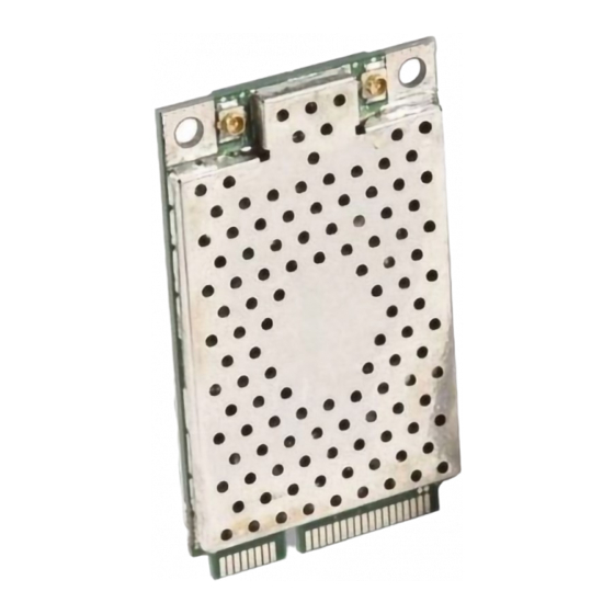
Introduction This document specifies the details for a IM11-PRT RFID MODULE About IM11 IM11-PRT RFID Reader Module is designed for quick integration into computers, printers, and any other products that need to be RFID-enabled. The IM11 includes these features: ... - Page 4 module is delivered. • Covers UHF bands from 865 to 928 MHz Supports four channel operation over the 865 to 868 MHz band. • Supports 50 channels in the FCC band from 902 to 928 MHz. • Supports the ISO 18000-6c protocol (EPC Class 1, Gen 2) •...
-
Page 5: Technical Specifications
Chapter Technical Specifications Physical Specifications Specification Values Physical 50.95 mm long x 30 mm wide x 4.76 mm thick Weight Environmental Specifications Specification Values Operating -20 °C to +60 °C Temperature Storage -40 °C to +70 °C Temperature Humidity 25 °C to 60 °C, 0% to 95% relative humidity, non-condensing process Shock 2000 g, 0.5 ms pulse, 10 times on each axis... - Page 6 Transmitter Specifications Specification Minimum Typical Maximum Unit Notes Frequency Stability Spurious In band Emissions - Out of band Spurious dBm Out of band Emissions - ETSI...
- Page 7 Thermal °C As measured by Shutdown sensor on module Thermal °C Recovery Transceiver Specifications Specification Values Output Power Control 29.5 dBm. User adjustable in 1 dB down to 10.5 dBm. Tolerance drift from +0.5 to -0.7. Bus Interface (USB or serial) USB 2.0 compliant client 12 Mbps (full speed) Serial 115.2 Kbps RF Output Impedance 50 Ohms with better than 10 dB return loss...
- Page 8 tags) 50 tags per second (using over air tags) Performance Testing AD 223 tags on cardboard Receiver Specifications Receiver Input Values Sensitivity Typical: -70 dBm 15 dB return loss Maximum Reverse Input Power Maximum: +20 dBm...
-
Page 9: Mechanical Integration
Mechanical Integration The module fits within the Mini PCI Express specifications. For physical dimensions, see the illustration. -
Page 10: Electrical Integration
Electrical Integration The module communicates either over USB or through serial: The USB client communication follows the CDC profile and i s USB 2.0- compliant, operating at 12 Mbps (full speed). In Serial mode, the module communicates as a standard PC COM port, operating at 115.2 Kbps. -
Page 11: Reader Power States
To reduce power, the module duty cycles its transmitter. The duty cycling happens according to the read commands that the application executes. To achieve the lowest power, after all tags are read, the transmitter turns off. After a period of time, the transmitter activates to identify new tags in the field. -
Page 12: Supported Antennas
Supported Antennas: These antennas are approved to work with iM11: Compact Yagi (6.0 dBi Linear) Microstrip Antenna, "Coupler” with -19.96 dBi gain Microstrip Antenna, "Coupler” with -24 dBi gain... -
Page 13: Mini-Pci Connector Pin Descriptions
Chapter Mini-PCI Connector Pin Descriptions Pin Descriptions Pin Name Description Reserved Do NOT connect +V_BATT Power input Reserved Do NOT connect Ground No Connect Not connected GPIO2 No Connect Not connected No Connect Not connected Ground No Connect Not connected No Connect Not connected No Connect... - Page 14 Ground Ground GPIO1 Ground GPIO3 Reserved Do NOT connect GPIO4 RESET_L Logic low level resets IM11 Ground Ground USB_DM USB data minus Ground USB_DP USB data plus +V_BATT Power input Ground +V_BATT Power input No Connect Not connected Ground GPIO5 HOST_CTS1 Future use GPIO6...
- Page 15 Input and Output Voltage Level Descriptions Transmit Power The module is able to adjust transmit power from 29.5 dBm to10.5 dBm, configurable in 1 dB steps with an accuracy (the measure of the power output for each level) of +/-0.5 dB. The initial tolerance (the measure of the power output for each level) is +/-0.5 dB.
-
Page 16: Agency Approvals
Chapter Agency Approvals FCC Communications commission interface statement Model: IM11PRT FCC ID: HD5-IM11R This device complies with Part 15 of the FCC Rules. Operation is subject to the following two conditions: 1. This device may not cause harmful interference. 2. This device must accept any interference received, including, an interference that may cause undesired operation. - Page 17 turning the equipment off and on, the user is encouraged to try to correct the interference by one or more of the following measures: • Reorient or relocate the receiving antenna. • Increase the separation between the equipment and receiver. •...
- Page 18 IMPORTANT NOTE: In the event that these conditions can not be met (for example certain laptop configurations or co-location with another transmitter), then the FCC authorization is no longer considered valid and FCC ID can not be used on the final product.
-
Page 19: Industry Canada
Industry Canada Model: IM11PRT IC: 1693B-IM11R This device complies with ISED's license-exempt RSSs. Operation is subject to the following two conditions: (1) this device may not cause harmful interference, and (2) this device must accept any interference, including interference that may cause undesired operation of the device. - Page 20 Approved antenna’s list Cet émetteur radio (IC : 1693B-IM11R/ Modèle : IM11-PRT) a été approuvé par l’ISED pour fonctionner avec le type d’antenne énuméré ci-dessous avec un gain maximal autorisé...
- Page 21 Cet appareil est destiné uniquement aux intégrateurs OEM dans les conditions suivantes : (Pour l’utilisation du module) 1) L’antenne doit être installée de telle sorte que 20cm soit maintenu entre l’antenne et les utilisateurs. 2) Le module émetteur ne peut pas être co-localisé avec un autre émetteur ou antenne.
- Page 22 End Product Labeling: This transmitter module is authorized only for use in devices where the antenna may be installed such that 20cm may be maintained between the antenna and users. The final end product must be labeled in visible area with the following: “Contains IC: 1693B-IM11R”.