MAKER MADE M2 Complete Beginner Assembly Manual
Automated cutting machine kit
Hide thumbs
Also See for M2:
- Setting up (52 pages) ,
- Complete beginner assembly manual (45 pages) ,
- Setup manual (14 pages)

Related Manuals for MAKER MADE M2


Summary of Contents for MAKER MADE M2
- Page 1 SETTING UP YOUR M2 AUTOMATED CUTTING MACHINE KIT The complete beginner assembly guide by Last Updated 1.18.2021 v2.0...
- Page 2 TABLE OF CONTENTS SECTION 1. Introduction - 3 SECTION 2. Parts Needed - 4 SECTION 3. Assembling the M2 - 7 SECTION 4. Building the Frame - 12 SECTION 5. Calibration and Operation - 21 SECTION 6. Appendices - 36 This work is licensed under the creative commons Attribution Non Commercial-No Derivatives 4.0 International license.
-
Page 3: Section 1. Introduction
M2! If you have experience with the Maslow, the M2’s older brother, you can use your existing frame! Just follow the steps to build the M2 and skip the part on Easel to learn how to calibrate with Makerverse. -
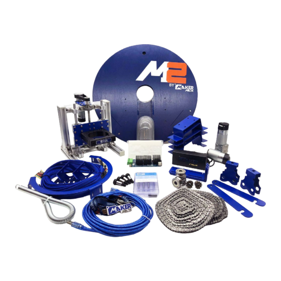
Page 4: Section 2. Parts Needed
M2 ASSEMBLY GUIDE SECTION 2. PARTS NEEDED This section contains information on what came with your M2 and other tools you will need to building and operation. Drew’s Note: Check out the M2 Video Playlist for an overview of what’s in the box and other how to videos! You’ll have to supply your own router for your M2. - Page 5 Router Clamp Roller Bearings (4) Chains 335cm/11’ (2) Dust Collection Elbow Spring Maker Made Router Bit Starter Maker Made Sticker, marker, Bag A welcome note, and USB Drive This work is licensed under the creative commons Attribution Non Commercial-No Derivatives 4.0 International license.
- Page 6 M2 ASSEMBLY GUIDE Bag B Bag C Bag D Bag E Bag F Bag G Bag H Bag Z Drew’s Note: Listed here are the contents of the bags. In the assembly portion, they will be referred to by their letter and number!
- Page 7 M2 ASSEMBLY GUIDE ASSEMBLING YOUR M2 The M2 kit comes in several pieces to assemble. It can be split into four main parts: Sled assembly, attaching belts and motor to Z-Axis Assembly, finishing the M2 assembly, and centering your router. It will probably take about 1.5 to 2 hours to build.
- Page 8 M2 ASSEMBLY GUIDE M2 ASSEMBLY PART 1: SLED ASSEMBLY (BAG C, BAG F, BAG G) 1. Attach three L-brackets to Sled by aligning with six small 2. Attach three L-brackets to rectangular brackets on ring predrilled holes, tall side toward center, using Phillips carriage, with the tall side closest to the middle.
- Page 9 M2 ASSEMBLY GUIDE M2 ASSEMBLY PART 2: ATTACH BELTS AND MOTOR TO Z-AXIS ASSEMBLY (BAG H) 1. Attach H1 Z motor bracket, but do not fully tighten (will 2. Attach Z motor to H1, with the motor shaft in the slot farthest tighten fully in Step 6), using H6 bolts and H9 Allen Wrench.
- Page 10 M2 ASSEMBLY GUIDE M2 ASSEMBLY PART 3B: FINISH M2 Z-AXIS ASSEMBLY (BAG Z) Drew’s Note: The Z-Axis Assembly attaches to the sled with 1. Mount Z-Axis assembly to sled by aligning extrusion “legs” T-nuts. They are marvels of engineering that are specially with the two rail “feet”...
- Page 11 1. Attach router bit to router, insert into router clamp, and 2. Loosen bottom T-nuts with Phillips screwdriver and move sled tighten clamp with Z5 Allen Wrench. back and forth until router bit is aligned with exact center of M2 sled hole. Drew’s Note: It’s very important...
- Page 12 BUILDING YOUR FRAME This Section is how to build your frame for your M2. It is split into six main sections: Building the wasteboard, building the top beam, leveling your frame and attaching your material, mounting the chains, mounting your M2, and connecting your DUE board.
- Page 13 ASSEMBLY GUIDE CONT. included with your M2 and will walk you through how to set up your kit to cut material almost to the edge of the 4x8’ space. These instructions are based on attaching the Top Beam to a wall. If you are interested in a different frame size or design, check out our M2 Resources page or the Owners group on Facebook for help! 1.
- Page 14 ASSEMBLY GUIDE CONT. ASSEMBLY GUIDE CONT. ASSEMBLY GUIDE CONT. ASSEMBLY GUIDE CONT. ASSEMBLY GUIDE CONT. M2 ASSEMBLY GUIDE BUILDING YOUR FRAME PART 1: BUILDING THE WASTEBOARD (BAG D) 4pcs long wood 304.8mm [12in] 304.8mm [12in] 304.8mm [12in] screws in Bag D 5.1mm [6.5in]...
- Page 15 Step 3: Attach last two Stud Mounts M2 ASSEMBLY GUIDE BUILDING YOUR FRAME PART 2: BUILDING THE TOP BEAM AND ADDING THE X/Y MOTORS (BAG D, BAG E) 1. Measure the distance from the ground to the bottom of the stud mount. Attach the other wasteboard stud mount to the stud on the opposite side at the exact same height.
- Page 16 D to attach top beam Use 8pcs short wood screws in Bag D to attach top beam M2 ASSEMBLY GUIDE BUILDING YOUR FRAME PART 3: LEVELING YOUR FRAME AND ATTACHING YOUR MATERIAL 3: Attach last two Stud Mounts 1. Mount the top beam to the wall using your guide marks from Step Two and ensure that it is level. To mount, ASSEMBLY GUIDE CONT.
- Page 17 The chain can snap back causing damage to people and surroundings! The M2 moves in the X and Y position by using chains connected to the motors. This guide is how to install the chains that came with your M2 on a standard 4’x8’ frame with a 10’...
- Page 18 3. Move M2 to center of Wasteboard and have a friend pull the tension on the opposite chain to around 20” from the nail to the spring. You can pull the chain away from the motor sprocket, pull for more length, and set it back to for the tension to hold, but beware of it pulling! When you have enough slack in the chain, thread through the opposite roller bearing carriage and attach with the other A1 cotter pin into second to last chain link.
- Page 19 Drew’s Note: The M2’s brain is an Arduino DUE microcontroller. We recommend mounting the DUE to the wall behind your Wasteboard, but it can be mounted in any safe location where it won’t be stepped on or conflict with the M2 during operation.
- Page 20 3. Right Motor will connect to M2) Drew’s Note: The X and Y motors move the M2 back and forth on the frame. If one of your motors of your M2 doesn’t move during operation, or the M2 generally moves in a strange direction, the first thing to check are the motor connections.
-
Page 21: Calibration & Operation
OPERATION & CALIBRATION PART 1: GET A DIGITAL .SVG FILE 1. Digital file: You must have a digital file to CNC with the M2. We suggest a black and white SVG file. There are many files available online and tutorials on how to create them on YouTube! 2. - Page 22 3. Choose depth: Click on your file and “cut” tab in the dialog box to choose how deep the M2 will cut. If your SVG is split into multiple parts or isolatable, you can select different parts of your file to cut different depths.
- Page 23 M2 ASSEMBLY GUIDE 4. Material dimensions: You can change material dimensions by clicking the “material” tab. Select the material you are cutting and the size to save it in the Gcode. 5. Resize/move: Once your model is selected, you can also resize it by dragging the small gray boxes around your file.
- Page 24 Change the bit settings to the same bit that is on your router. Click the “bit” tab and select your bit. There are preset bits for the X-carve, but the best way to change it for the M2 is to scroll to the bottom of the tab and manually type in your bit size.
- Page 25 (0,0). You can arrange your file to start based on where you home your M2. Either select and move all the parts of your file or click the “shape” tab in the dialog box after selecting your model. Click the bubble in the five part matrix to choose where your M2 will start.
- Page 26 M2 ASSEMBLY GUIDE 9. File management: To keep track of the Gcode files you create to use them again, we suggest naming the file with the bit size and thickness of the material. Click “untitled” in the menu bar to change the name.
- Page 27 M2 ASSEMBLY GUIDE 10. Generate Gcode: To generate your Gcode to cut, click “Machine” > “Advanced” to bring up the Gcode menu. Then click “Generate g-code”. This work is licensed under the creative commons Attribution Non Commercial-No Derivatives 4.0 International license.
- Page 28 M2 ASSEMBLY GUIDE Then “Export g-code” to save the Gcode. You will upload this Gcode into the Machine Control Application. You can leave the other default setting alone until you become more comfortable with your M2. You finished exporting and are ready for the next stage! This work is licensed under the creative commons Attribution Non Commercial-No Derivatives 4.0 International license.
- Page 29 You need a machine control application (also known as a Gcode sender). We suggest our Makerverse for your M2 and many other CNC machines. It’s based off the open source CNCjs software. Coming soon to the Windows and Apple Stores, you can download it for your Windows, Mac, or Linux computer here: http://www.makerverse.com/...
- Page 30 Choose the “Standard 18-inch Circle” for your M2. 6. CONNECT YOUR M2: Plug your M2 USB into your computer and the power plug into the socket. Click the drop down menu and choose the port that reads “Arduino LLC” and click connect! Drew’s Note: If you don’t see your M2 right away, click the refresh button next to connect.
- Page 31 M2 ASSEMBLY GUIDE 7. VERIFY CONNECTION AND FIRMWARE You will know your M2 is connected when you see the information about your machine fill out around the connection screen. Verify that your firmware on the bottom tab is the same as the link: v20200915. If it is a lower...
- Page 32 If the X, Y, and Z motors are not plugged in completely to the motors and Arduino DUE Board, the M2 will not follow your commands and will act wonky (like continuing to move when you only told it to move 1 inch).
- Page 33 M2 ASSEMBLY GUIDE OPERATION AND YOUR FIRST CUT After calibration, you are ready to cut! Here are the instructions over how to cut with your M2. 1. UPLOAD GCODE: Click “Upload Program” and select the Gcode file you created in Easel.
- Page 34 Drew’s Note: When your M2 is cutting for the first time, be close to the power source to stop all operation if something goes awry. After your first cut, you should measure and compare the real values of your square cut to the values of your Gcode for scaling.
- Page 35 M2. Then you could cut the same project out of different sections of your material! To set the work position, jog the M2 to the position on your material where you want to begin. Then click the “Zero Out Machine” locator icons for X and Y under Work Position to set your new Work Home.
-
Page 36: Appendix 1 - Tips
Makerverse does not control your router, it only controls your M2. You must manually turn your router on and off. In case of an error always turn off your router before you turn off your M2. Always remember to turn on your router before clicking “Run” in Makerverse and turn off your router after the M2 is paused, stopped, or has completed the project. -
Page 37: Appendix 2 - Troubleshooting
6. Make sure all of the T-nuts, bolts, and screws are tight on your M2 and frame. 7. If your M2 is slanting on different materials, increase the RPM of your router and decrease your cut per pass depth. Your bit can pull the M2 sled in different directions based on the depth, bit, and RPM. -
Page 38: Appendix 3 - Links
M2 ASSEMBLY GUIDE APPENDIX 3 - LINKS Click here to check out updates on our FAQ section! Easel: https://www.inventables.com/technologies/easel Inkscape: https://inkscape.org/ M2 Resources: https://makermade.com/m2-resources/ Makerverse: https://makermade.com/resources/ Makerverse Calibration Video: https://youtu.be/HsnEQgeWrmI Marketplace: https://makermade.com/marketplace/ Router Guide: https://makermade.com/m2-resources/ Weekly Beginner Training Link: https://makermade.com/resources/ YouTube Playlists: https://www.youtube.com/c/MakerMadeCNC...