
Related Manuals for Honeywell H Series


Summary of Contents for Honeywell H Series
- Page 1 H-Series Green Class Net Meter ADVANCED KWH/DEMAND METER WITH CO2 FOOTPRINT INSTALLATION INSTRUCTIONS Place bar code here 62-0424-02...
-
Page 2: Table Of Contents
H-SERIES GREEN CLASS NET METER TABLE OF CONTENTS Section 1.0 Introduction Section 2.0 Internal Electronic Assemblies Section 2.1 Main Power Board Section 2.2 Display Board Section 2.3 Input Board Section 3.0 Meter Technical Specifications Section 4.0 Safety Label Definitions and Information Section 5.0 Precautionary/Safety Information Section 6.0... -
Page 3: Introduction
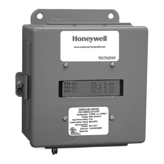
H-SERIES GREEN CLASS NET METER 1.0 INTRODUCTION The Honeywell Green Class Net meter is a 3-phase meter with communications. The device is used to monitor electric power usage of individual loads after the utility meter and store kW and kVAR data for automatic meter reading. The Green Class Net meter is dual protocol capable and provides both RS485 and Ethernet communications. - Page 4 H-SERIES GREEN CLASS NET METER CAUTION Internal circuit card components are extremely sensitive to electrostatic discharge. Prior to handling or touching internal circuitry, discharge any static buildup on your person. To discharge yourself, touch a grounded metal object such as conduit or an earth grounded metal enclosure. WARNING Use of this instrument, Green Class Net meter, in a manner inconsistent with this manual or not specified by the manufacturer in writing, can cause...
- Page 5 H-SERIES GREEN CLASS NET METER 2.0 INTERNAL ELECTRONIC ASSEMBLIES The unit is comprised of two major subassembly boards, the main power board and the display board. Both circuit boards are mounted inside either a JIC STEEL Enclosure. MAIN POWER DISPLAY BOARD BOARD M33270...
- Page 6 H-SERIES GREEN CLASS NET METER 2.1 Main Power Board Connections to this board include the MAIN Power Input and current sensors. The MAIN Power Input terminals are positions one through four on the four position screw terminal block, TB1. These terminals are covered with a protective shield for safety purposes.
- Page 7 H-SERIES GREEN CLASS NET METER 2.2 Display Board The display board connects to the main power board via a flex ribbon cable and the board mounts on the inside of the housing door. No additional connections to the display board are required. The display board’s LCD readout indicates the metered values as well as errors associated with the Green Class Net meter, such as phase loss or sensor error conditions.
-
Page 8: Input Board
H-SERIES GREEN CLASS NET METER 2.3 Input Board The Green Class Net meter is supplied with an input board which allows it to accept pulses (dry contact) from third party meters, such as gas, water, BTU, etc. This 3rd party meter information that comes in through the pulse input can be communicated via the communication protocols. -
Page 9: Meter Technical Specifications
A-BB-CCC-DDDD-E-FF-G- HHH, where: A = Brand: H for Honeywell BB = designates Class: 320 (32) or 500 (50) meter CCC = input voltage: (208, 480, 600, 120 volt for high voltage applications only) - Page 10 H-SERIES GREEN CLASS NET METER 3.0 METER TECHNICAL SPECIFICATIONS Input Voltage 3-wire (Delta) Or 4-wire (Wye) Configuration Mains Voltage Input Up To 600 VAC RMS Available Input Power 12 VA Maximum Rating Current Sensor Rating Up To 3200 Amps RMS AC Available Power Factor 0.5 Leading Or Lagging Line Frequency...
- Page 11 H-SERIES GREEN CLASS NET METER RS-485 Serial Cable: UL-listed/rated Telephone Cord. 4-cond. Communications Input/output Ground-isolated +/-5.4VDC Voltage: Cable Connector: Screw Terminal Termination Circuit Input 5.3kVAC Isolation: Max Cable 4000 Feet Distance: Max Network 64 Cabling Nodes (Including Master) Nodes: Default Baud Rate: 9600 for EZ-7 Recommended Manufacturer: Littlefuse...
-
Page 12: Safety Label Definitions And Information
H-SERIES GREEN CLASS NET METER 4.0 SAFETY LABEL DEFINITIONS AND INFORMATION The Green Net Class meter may contain one or more of the following labels. Operator(s) should familiarize themselves with the meaning of each label to minimize risk. FCC Notice This equipment has been tested and found to comply with the limits for a Class B digital device, pursuant to part 15 of the FCC Rules. -
Page 13: Precautionary/Safety Information
H-SERIES GREEN CLASS NET METER 5.0 PRECAUTIONARY AND SAFETY INFORMATION CAUTION Internal circuit card components are extremely sensitive to electrostatic discharge. Be careful not to touch internal circuitry prior to discharging any static buildup on your person. To discharge yourself, touch a grounded metal object such as conduit or an earth-grounded metal enclosure. -
Page 14: Mounting The Green Class Net Meter
H-SERIES GREEN CLASS NET METER 6.0 METER INSTALLATION 6.1 Mounting the Green Class Net Meter 6-35/64 (166) 5/8 (16) 6-35/64 (166) 7-51/64 (198) Ø 1-3/32 (28) THROUGH 3-17/64 (83) NEAR SIDE ONLY 3-25/64 (86) 1-5/8 (41) M34684 Fig. 5. Enclosure Dimensions Use appropriately sized mounting hardware to fasten the meter enclosure to the selected mounting surface. - Page 15 H-SERIES GREEN CLASS NET METER WARNING Failure to attach the protective earth ground wire securely to the meter creates a potential shock hazard. Do not operate the meter without a protective earth ground connection securely installed. 3. Wire Entry: One 3/4” conduit opening is located on the bottom of the unit enclo- sure.
- Page 16 H-SERIES GREEN CLASS NET METER d. Connect the three AC main power wires (Phases A, B and C) to their respec- tive positions as labeled on terminal block TB1 and tighten to 7 in-lb. After all conductors are connected to each of their respective terminal block positions and tightened down, verify that each terminal block screw is securely fas- tened by gently tugging on each conductor.
-
Page 17: Phasing Of Line Voltage
H-SERIES GREEN CLASS NET METER Verify the voltage readings on Screen 7 using an AC voltmeter. Typical read- ings shown below are measured phase to neutral for 4 wire and phase to phase for 3 wire. Readings should be +/- 10% of nominal. Meter Type Nominal Voltage Limits (+/- 10%) -
Page 18: Current Sensor Installation & Wiring
H-SERIES GREEN CLASS NET METER Once the meter displays the correct line voltages and there are no error messages, you are ready to connect the current sensors to the meter. Before continuing with the installation, verify that the nine screens display as follows: Screen 1:Total Kilowatt-Hours, (kWh), Delivered, Received, NET Screen 2: KWH Screen 3: CO2... - Page 19 H-SERIES GREEN CLASS NET METER 6.4.1 Installing the Split-Core Current Sensor Assembly 1. Each phase being monitored will require one two-piece current sensor assembly. Open the two-piece current sensor assembly by releasing the nylon clamp using a fl at head screwdriver. Fig.
- Page 20 H-SERIES GREEN CLASS NET METER 6.4.2 Current Sensor Wiring Once the current sensors are installed onto their appropriate phase conductors, you can begin terminating the current sensors onto the Green Class Net meter main board. The current sensors can be extended up to 500 feet for remote monitoring applications.
-
Page 21: Main Power & Current Sensor Wiring Diagram
H-SERIES GREEN CLASS NET METER 6.5 Main Power & Current Sensor Wiring Diagram TERMINAL BLOCK LOCATED INSIDE E-MON D-MON METER ® LINE VOLTAGE CURRENT SENSORS ØA ØB ØC Ø Ø Ø LOAD SOURCE RECOMMENDED FUSES OR CIRCUIT BREAKER PER THE NATIONAL ELECTRICAL CODE (METER LOAD 6VA.) NEUTRAL NOT USED IN DELTA SYSTEM. -
Page 22: Line Voltage/Current Sensor Diagnostics
H-SERIES GREEN CLASS NET METER 6.6 Line Voltage/Current Sensor Diagnostics Following is a list of diagnostic messages that may appear on the meter display. DIAGNOSTIC MESSAGES SHOULD NOT BE ON CONTINUOUSLY WHEN THE METER IS INSTALLED PROPERLY AND IS IN WORKING ORDER. 6.6.1 Line Voltage Diagnostics The diagnostics program detects line voltage faults by displaying one of two messages:... - Page 23 H-SERIES GREEN CLASS NET METER 6.6.2 Current Sensor Diagnostics The load current must be at least 1% of the meter’s rated load in order to use the diagnostic function. Current sensor diagnostics can detect: 1. Reversed current sensors. 2. Incorrect phase correspondence. 3.
-
Page 24: Rs-485 Wiring
H-SERIES GREEN CLASS NET METER 6.7 RS-485 Wiring RS-485 communication allows a computer or modem to communicate with one or more Green Class Net meters. You can connect as many as 52 meters along a 4000- 4000 foot RS-485 cable run. Green Class Net meters are available with your choice of RS-485 communication options: Modbus, BACnet, E-Mon Energy (EZ7) Standard. - Page 25 H-SERIES GREEN CLASS NET METER 6.7 RS-485 Wiring (Continued) Connect the GND terminals of PORT 1 of each Green Class Net meter so that the GND terminals on all meters are linked, GND to GND to GND. RS-485 TERMINAL M33274 Fig.
-
Page 26: Rs-232 Communications
H-SERIES GREEN CLASS NET METER 6.8 RS-232 Communications 6.8.1 Hardwired System using the RS-232 Communication Key (for connecting an EZ-7 meter to a computer with E-MON Energy™ software) The RS-232 communications key (part number: SUB-RS232K) allows you to connect Green Class Net meters that use E-7 protocol to a personal computer that has the E- Mon Energy™... - Page 27 H-SERIES GREEN CLASS NET METER 3. Connect the provided AC adapter into the rear panel input on the RS- 232 key. Plug the adapter into a 120VAC outlet. On the front panel of the RS-232 key, two LEDs (POWER ON and AC ON) will light up. NOTE: When the E-Mon Energy™...
- Page 28 H-SERIES GREEN CLASS NET METER 6.8.4 External Modem 1. All meters should be connected to the RS-232 key as described in 6.8.2. 2. DISCONNECT POWER TO THE RS-232 KEY. Remove the cover by removing the 2 screws from the bottom of the enclosure. 3.
- Page 29 H-SERIES GREEN CLASS NET METER 6.8.5 Baud Rate Selection The communication baud rate is selected by means of a jumper on the circuit board. Baud Rate is applicable for EZ-7 PROTOCOLS. Factory default is 9600 for EZ-7. Maximum baud rate is 19200 for EZ-7. Minimum baud rate is 9600. 1.
-
Page 30: Connecting Green Class Net Meters To Usb Key Using Rs485
H-SERIES GREEN CLASS NET METER 6.9 Connecting Green Class Net Meters to the USB Key Using RS485 The USB Key plugs into the PC’s USB port and provides a termination point for the RS485 wiring from the meters. Up to 52 meters can be “Daisy chained” with up to 4000 feet total RS485 wiring. -
Page 31: Ethernet Communications
H-SERIES GREEN CLASS NET METER 6.10 Ethernet Communications Ethernet/IP communications connections are provided through an RJ-45 connector(J8) in the lower right corner of the main power board. This port can be connected directly to a network port of a PC using a Cat. 5e crossover cable. Two LEDs are provided directly above the connector. -
Page 32: Multiple Load Monitoring
H-SERIES GREEN CLASS NET METER 7.0 MULTIPLE-LOAD MONITORING The Honeywell Green Class Net meter provides extreme flexibility by allowing additional sets of current sensors to be used in parallel so multiple load locations can be monitored by one meter. This feature allows a totalized display readout from two or more load circuits. - Page 33 H-SERIES GREEN CLASS NET METER NOTE: One set of current sensors equates to three sensors, one per phase. The multiplier only applies when extra sets of current sensors are installed on one meter. If you are using only one set of three current sensors, the multiplier is not required.
-
Page 34: Preventative/Scheduled Maintenance
H-SERIES GREEN CLASS NET METER LINE VOLTAGE CURRENT SENSORS ØAØB ØC N B W B W B W ØA ØB LOAD SOURCE LOAD A ØA ØB LOAD SOURCE LOAD B INSTALL JUMPER WIRE. M34644 Fig. 18. Single Phase Multiple-load Wiring Diagram. 8.0 PREVENTATIVE/SCHEDULED MAINTENANCE The unit is shipped in a calibrated and fully functional tested condition. -
Page 35: Lithium Battery Replacement
H-SERIES GREEN CLASS NET METER 9.0 LITHIUM BATTERY REPLACEMENT INSTRUCTIONS The Green Class Net kWh/Demand meter has a Lithium Battery Cell, which is used to retain the contents of SRAM and the RTC during power outages. The battery has a life expectancy of greater than 5 years. - Page 36 H-SERIES GREEN CLASS NET METER The battery cell is mounted in a coin cell on the upper right side of the main power board. Replace the battery if the low battery warning is on display. – BATTERY M33278 Fig. 20. Lithium Battery Cell. Use the following procedure to replace the battery cell STEP 1: Disconnect power from the meter at the unit external circuit breaker.
-
Page 37: Green Class Net Meter Features
H-SERIES GREEN CLASS NET METER 10.0 GREEN CLASS NET METER FEATURES 10.1 Display Board Push Buttons DOWN MENU SELECT M33279 Fig. 21. Push Buttons. The display board has four push button switches (DOWN, UP, SELECT, MENU) that can be used to configure the following: Date &... - Page 38 H-SERIES GREEN CLASS NET METER 10.1 Display Board Push Buttons (Continued) To access any of these items press the MENU button. To scroll down the list press the MENU button until the desired item is indicated by the arrow. Then push the SELECT button to enter the configuration screen for that item.
- Page 39 H-SERIES GREEN CLASS NET METER 10.1 Display Board Push Buttons (Continued) Display Hold Feature You can “lock” the scrolling display so that it will stay locked on any one of the six screens. On the inside of the door, locate the 4 buttons at the top of the Display Board: Down, Up, Select and Menu.
-
Page 40: Reading The Green Class Net Meter Display
H-SERIES GREEN CLASS NET METER 10.2 Reading the Green Class Net Meter Display The Green Class Net meter features nine different displays showing information in 5 second scrolling intervals. Explanations of these displays are as follows: Screen 1: Total Kilowatt-Hours (kWh) Delivered - Received - NET Screen 2: KWH Screen 3: CO2... -
Page 41: Frequently Asked Questions
H-SERIES GREEN CLASS NET METER 11.0 FREQUENTLY ASKED QUESTIONS Q. When providing line voltage to the meter, can I tap off of the same breaker I am monitoring? A. Yes, the voltage can be pulled from the same breaker being monitored. Q. -
Page 42: Modbus Point Maps
H-SERIES GREEN CLASS NET METER 12.0 MODBUS POINT MAPS Modbus Integer Registers: Green Address Reg Description Units Meters 40001* Energy delivered kWh Pulse 40003 Energy received kWh Pulse 40005 Reactive energy delivered kVARh Pulse 40007 Reactive energy received kVARh Pulse * To clear single meter kWh/kVARh, set multiple points at 40001 for 8 points with data set to 0000 0000 0000 0000 0000 0000 0000 0000. - Page 43 H-SERIES GREEN CLASS NET METER Modbus Float Registers: 41043 Apparent power, phase B 41045 Apparent power, phase C 41047 Power factor, phase A % PF 41049 Power factor, phase B % PF 41051 Power factor, phase C % PF 41053 Current, phase A Amps 41055...
- Page 44 H-SERIES GREEN CLASS NET METER BACnet Object Descriptors: Analog Input Reactive energy received kVARh Present Value R Analog Input Real power Present Value R Analog Input Reactive power kVARh Present Value R Analog Input Apparent power kVARh Present Value R Analog Input Power factor % PF Present Value R...
- Page 45 H-SERIES GREEN CLASS NET METER BACnet Object Descriptors: 26 Analog Input Power factor phase C % PF Present Value R 27 Analog Input Current phase A Amps Present Value R 28 Analog Input Current phase B Amps Present Value R 29 Analog Input Current phase C Amps Present Value R...
- Page 46 H-SERIES GREEN CLASS NET METER Lonworks SNVT Types Point Map: Green Network Variable Name SNVT Type Description Units Meters nvoKWh_Del SNVT_count_inc_f Energy delivered nvoKWh_Rec SNVT_count_inc_f Energy received nvoKVarh_Del SNVT_count_inc_f Reactive energy kVARh R delivered nvoKVarh_Rec SNVT_count_inc_f Reactive energy kVARh R received nvoReal_Pwr SNVT_count_inc_f Real power...
- Page 47 H-SERIES GREEN CLASS NET METER Lonworks SNVT Types Point Map: nvoPwr_Fact_PhC SNVT_pwr_fact_f Power factor, phase % PF nvoCurrent_PhA SNVT_amp_f Current, phase A Amps nvoCurrent_PhB SNVT_amp_f Current, phase B Amps nvoCurrent_PhC SNVT_amp_f Current, phase C Amps nvoVolt_LN_PhA_N SNVT_volt_f Voltage, line to Volts-N R neutral, phase A-N nvoVolt_LN_PhB_N SNVT_volt_f...
-
Page 48: Meter Limited Warranty
H-SERIES GREEN CLASS NET METER 13.0 METER LIMITED WARRANTY Subject to the exclusions listed below, Honeywell will either repair or replace (at its option) any product that it manufactures and which contains a defect in material or workmanship. The following exclusions apply: This Limited Warranty is only effective for a period of (5) five years following the date of manufacture when installed in accordance with manufacturer’s instructions by...