
Related Manuals for ACI Laser DPL Nobilis Marker

Summary of Contents for ACI Laser DPL Nobilis Marker
- Page 1 LASER MARKING SYSTEMS Operating Instructions DPL Nobilis Marker Business Diode GN DPL Lexis Marker Business Diode UV OEM Version Laser Device Class 4 Mark your territory...
- Page 2 The manufacturer shall only be responsible for the safety characteristics of this device within the scope of the legally applicable regulations if it is operated by the user in accordance with the operating instructions and repaired by ACI Laser GmbH itself or someone appointed by and acting under the instructions of ACI Laser GmbH.
-
Page 3: Table Of Contents
Table of Contents Table of Contents Introduction ..........................7 Important Information ........................7 Intended Use ..........................8 Improper Use ..........................9 Notices in the Document ......................9 Warranty ............................11 Technical Customer Service ..................... 12 Safety ............................13 Basic Safety Instructions ......................13 Functional safety ........................ - Page 4 Table of Contents Laser electronics ........................23 Laser Safety Device (SD) ......................23 Technical Data ..........................25 Laser device ..........................25 Connection values ........................25 Fuse protection ......................... 25 Interfaces ..........................26 Scan unit ........................... 26 Focusing objectives (optional) ....................26 Beam source dimensions incl.
- Page 5 Table of Contents Operation ............................ 44 Operating and Display Elements ....................44 Control elements ........................44 Multi function display ......................... 45 Starting the Laser Marking Device ................... 46 Handling ............................47 Fault Finding ..........................47 6.4.1 General Faults ..........................47 6.4.2 Specific Faults ..........................
- Page 6 Table of Contents...
-
Page 7: Introduction
• optimisation for the intended purpose. The DPL Nobilis Marker and the DPL Lexis Marker are state-of-the-art devices. The EC Declaration of Incorporation and the EC Declaration of Conformity confirm that the man- ufacturer has complied with the relevant directives. The CE-symbol is located on the type plate. -
Page 8: Intended Use
6 of DGUV no. 11 "Laser Radiation" to ensure that the relevant safety guidelines and standards are observed. • The DPL Nobilis Marker and the DPL Lexis Marker laser marking systems are intend- ed to be used exclusively for marking applications in conjunction with the associated Magic Mark software. -
Page 9: Improper Use
Important Information Improper Use All other uses other than use for the intended purpose, including that with other control software, shall be deemed to be improper use. The laser marking device must not be used by: • persons who have not read or understood these operating instructions, •... - Page 10 Important Information DANGER RISK OF DEATH OR SERIOUS INJURIES! Indication of an imminent danger, which will result in death or serious injuries if the appropriate precautionary measures are not taken. WARNING DANGER OF INJURIES AND/OR RISK OF PROPERTY DAMAGE. Indication of an immediately impending hazard which can cause serious injuries or property damage if the appropriate precautionary measures are not taken.
-
Page 11: Warranty
Important Information Warranty The manufacturer guarantees that the product does not have any manufacturing or mate- rial defects. The warranty period shall be 12 months from the dispatch date in as far as no other con- tractual ruling has been made. The scope of warranty is limited to the repair or replacement of the product supplied by the manufacturer. -
Page 12: Technical Customer Service
Important Information Technical Customer Service ACI Laser GmbH Steinbrüchenstraße 14 D-99428 Grammetal OT Nohra Germany Phone: +49 3643 4152-0 Fax: +49 3643 4152-77 service@ACI-Laser.de www.ACI-Laser.de NOTICE The laser device may only be maintained and repaired by the manufacturer. Any manipulations on the device or breaking the warranty seal will void any claims... -
Page 13: Safety
14 years, at the latest, in order to maintain performance level e. Laser class As an OEM component, the DPL Nobilis Marker and the DPL Lexis Marker are class 4 laser marking devices according to DIN EN 60825-1 "Safety of Laser Devices". -
Page 14: Emissions
Safety The following measures must be taken in order to be able to categorise the DPL Nobilis Marker and the DPL Lexis Marker as a class 1 laser device (accessible laser radiation is harmless): • Ensure that the entire beam path to the work piece is shielded beam-tight. •... - Page 15 Safety - mists or - other reaction products to be given off from the material surface. These may be toxic, depending upon the material being processed. The operating company must therefore provide effective extraction. Information about this can be found, for example, in the VDI guideline 2262 1...3 "Air Quality in the Work Place". •...
-
Page 16: General
Safety • General Read the operating instructions and always keep them in an accessible place. • Do not mark any easily flammable or combustible materials. • Do not transport, store or operate the device in a vertical position. There is a risk of damaging optical components. •... -
Page 17: Operation
Safety and that none of the vents are covered. The vents must be clear and free of any residual packing material. • Mount the device at the installation site in accordance with the regulations. • Ensure that the shutter is active (closed) during the set up. The main beam is simulated by a pilot laser. -
Page 18: Labels At The Device
The warning notices on the device point out possible hazards from the laser and provide information about the basic performance data of the laser units. • On the top of the enclosure (1): DPL Nobilis Marker DPL Lexis Marker AVOID EXPOSURE TO RADIATION AVOID EXPOSURE TO RADIATION... -
Page 19: Type Plate
• date of manufacturing, • operating voltage/frequency range, • power consumption and • device fuse. Marker ACI Laser GmbH Model: Steinbrüchenstraße 14 Serial Number: 2001NL0580 99428 Grammetal OT Nohra Germany Manufacturer: ACI Laser GmbH phone: + 49(0)3643 4152-0 Date of Manufacturing:... -
Page 20: Description
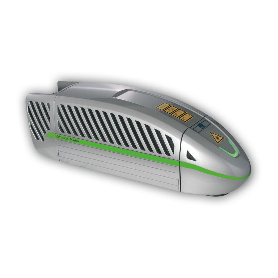
Description Description Overview The functional units of the laser marking device contain the following components: (1) air cooling for beam source (2) multi function display (3) focal lens (4) laser electronics, beam source, beam expander and shutter (5) galvanometer scan unit (6) power input module and interfaces... -
Page 21: Intended Purpose
• minimal stress on the material and • minimal change in its properties. These requirements are optimally fulfilled by the DPL Nobilis Marker and the DPL Lexis Marker. The laser marking device is a highly-integrated marking system. The components •... -
Page 22: Principle Of Operation
Q-switch. Depending on the configuration frequency conversion takes place inside a resonator with a SHG (second harmonic generation) crystal in the visible spectral range at 532 nm (DPL Nobilis Marker) or by another THG (Third Harmonic Generation) crystal at 355 nm (DPL Lexis Marker). -
Page 23: Shutter
Description Shutter A swivelling screen is arranged in the laser. The laser process is interrupted by closing the shutter. Pilot laser The wavelength of the working laser is not in the visible range. The light of a low power red laser diode is reflected into the beam path between the shutter and scanhead to check the marking window. - Page 24 Description Opening the interlock circuits will immediately cause the diaphragm to swivel into the beam path, thus interrupting the laser process. In the event of the following errors: • Exceeding the defined time period of 200 ms upon opening or closing the diaphragm, •...
-
Page 25: Technical Data
Description Technical Data Laser device DPL Nobilis Marker Laser material: Nd:YVO4, frequency-doubled Wave length: 532 nm Laser power: Pulse repetition rate: 60 - 300 kHz Pilot laser: 650 nm, < 390 µW Laser class: Performance level: DPL Lexis Marker Laser material:... -
Page 26: Interfaces
- optional connections for encoder Scan unit Aperture: 9 mm Scanning speed: < 10 m/sec Focusing objectives (optional) DPL Nobilis Marker 100 Spot diameter 13 µm Marking field size: 50 mm x 50 mm Focusing length 136 mm ± 3 mm... -
Page 27: Beam Source Dimensions Incl. Scanner
Description Focusing length 305 mm ± 5 mm DPL Lexis Marker 100 Spot diameter 9 µm Marking field size: 60 mm x 60 mm Focusing length 155 mm ± 3 mm DPL Lexis Marker 162 Spot diameter 15 µm Marking field size: 95 mm x 95 mm Focusing length 248 mm ±... -
Page 28: Technical Drawing
Description Technical drawing 9 (16 x) 178.5 153.5 128.5 72.5 47.5 22.5... -
Page 29: Scope Of Delivery
Description Scope of Delivery • DPL Nobilis Marker or DPL Lexis Marker laser device completely mounted, • power cable, • connection cable for USB 2.0, • 37-pin sub-D housing to wire the laser control interface, • 9-pin sub-D housing to wire the interlock connection, •... -
Page 30: Installation
The laser marking device is delivered in a packaging which meets UPS "falling regula- tions". From the inside outwards: • DPL Nobilis Marker or DPL Lexis Marker laser device completely mounted, • foam grid, • vacuum-tight, welded aluminium foil with desiccant, •... -
Page 31: Mechanical Installation
Installation Mechanical Installation WARNING RISK OF PERSONAL INJURIES AND MATERIAL DAMAGE FROM LASER RADIATION! All safety-related devices must be installed and their effectiveness proven before the system is started up. The acceptance must be per- formed by the laser safety officer and recorded in writing. For safety reasons, the laser must not be activated until all the above- mentioned conditions have been fulfilled. -
Page 32: Assembly
Installation Assembly A mounting surface (1) is provided on the underside of the device to enable it to be me- chanically integrated into a system. The position of the bore holes (measured in mm) for - M6 fixing screws (3) with washers/tooth lock washers - alignment pins (2) ø6 H7 178.5 can be seen in the drawing on the left. -
Page 33: Swivelling The Scan Unit
Installation Swivelling the scan unit Loosen the fixing screw (2) of the clamp ring (1). Rotate the scan unit through the permissible swivelling range. CAUTION RISK OF DAMAGING THE CABLE HARNESS! Avoid the damage of the cable harness when rotating the scan unit. Lock the scan unit by hand-tightening the fixing screw (2). -
Page 34: Focusing
The distance (A) between the lower edge of the scan unit (2) and the surface of the work- piece (1) depends upon the type of objective used: Type Marking field size DPL Nobilis Marker 100 136 mm ± 3 mm 50 mm x 50 mm 210 mm ± 3 mm 100 mm x 100 mm 305 mm ±... -
Page 35: Installing The Marking Software
Installation Installing the Marking Software • Minimum hardware requirements PC with 64 bit operating system Windows 7 or 10, • CD ROM drive, • 1 free USB 2.0 interface, • monitor (recommendation: 17 inch), • keyboard, mouse. If necessary, you will receive this additional information from the manufacturer. Installation Start your PC. -
Page 36: Electrical Installation
Installation Electrical Installation 5.4.1 Interfaces WARNING DANGER OF INJURIES AND/OR RISK OF PROPERTY DAMAGE! The device interfaces may only be connected to the plant by an electri- cian in cooperation with a laser safety officer! The interfaces are located on the back above the laser diode module: (1) the power input module with integrated power switch and drawer for fine fuses (2) power switch (3) interlock connection, 9-pin, sub-D... -
Page 37: Interlock Connection
Installation Interlock connection INTL1_OUT INTL1_IN INTL2_OUT INTL2_IN SD-READY D-SUB-9F Interlock circuit 1 and 2 Pin 1, pin 6 INTL1_OUT, INTL1_IN external interlock circuit 1 Pin 2, pin 7 INTL2_OUT, INTL2_IN external interlock circuit 2 In order to integrate the laser marking device into an external, dual-channel, safety circuit, 2 potential-free independent safety switches must be wired between pin 1/6 and pin 2/7 (see image). - Page 38 Installation To this end, it must be ensured (mechanically) that both switches reliably within a period of 150 ms. Alternatively for the use of potential-free safety switches, it is possible to use a safety relay based on Performance Level e with appropriate wiring in accordance with the manufac- turer's specifications.
-
Page 39: Laser Control Interface
Installation Laser control interface The Laser control interface is realised by a 37-pin, sub-D, panel socket, two-rowed. Depending upon the application case, the laser control interface may be wired by the user. D-SUB-37F EMISSION READY OUT1 OUT2 OUT3 OUT4 OUT5 OUT6 OUT7 OUT8... - Page 40 Installation External emission light Pin 22 EMISSION 24 V, max. 200 mA, protected by polyfuse. Pin 22 carries 24 V when the shutter is open. The connected emission warning light signals danger from laser radiation. WARNING DANGER OF INJURIES AND/OR RISK OF PROPERTY DAMAGE FROM LASER RADIATION! Wiring this output is specified for operation in accordance with a class 4 laser.
- Page 41 Installation electronically secured, short-circuit-proof, Inductive loads may be connected. There is an internal freewheel diode. Pin 2, 4, 21 GND I/O Reference points for all 24 V inputs and outputs as well as READY and EMISSION The inputs can be queried during a marking cycle and so start e.g. a marking job. The free- ly programmable outputs can, for example, be used to indicate the end of an inscription.
-
Page 42: Connection
Installation 5.4.2 Connection Power connection Ensure that the device power switch (2) is switched off. Connect the supplied power cable to the power input module (1) of the laser device. Connect the power cable to a safety contact socket. Connection with the PC The marking software must be installed. -
Page 43: Checking The Installation
Installation Checking the Installation CAUTION RISK OF PROPERTY DAMAGE. Perform the following tests to avoid material damage. Please check the following points again before you start your laser system: • Have the mechanical and electrical installations been performed correctly and com- pletely? •... -
Page 44: Operation
Operation Operation Operating and Display Elements Control elements The laser marking system just has a power switch (1) beside the power input module. -
Page 45: Multi Function Display
Operation Multi function display On the multi function display (1) the current working state of the laser marking device is to be seen. Display State Meaning Dark blue Offline Device switched on, Software not started or no communication Dark-straw Communication exists, laser not activated Dark green with pale yellow On (not Laser activated, not ready for operation... -
Page 46: Starting The Laser Marking Device
Operation Starting the Laser Marking Device NOTICE Keep to the switching sequence on each start. Start the control PC. Wait until the operating system has completely loaded. Switch on the device power switch. NOTICE The interlock circuits must be open when switching on the device. Follow the Windows installation instructions during the initial commissioning. -
Page 47: Handling
Operation Handling The laser marking device is operated via the marking software. All operating sequences are controlled from the control PC via the laser control interface. All the parameters are exclusively entered on the keyboard of the control computer. NOTICE Detailed information for using the marking software is contained in the software manual provided. - Page 48 Operation Problem/Fault Possible cause Elimination Laser will not start USB cable not connected Check whether the cable is plugged in correctly. properly Interlock circuits closed Open the interlock circuits (must always be open upon system start-up). SD error Start the marking software and check status / error reports in the status bar, respectively in the message window, to receive detailed information.
-
Page 49: Specific Faults
Operation 6.4.2 Specific Faults The Magic Mark marking software monitors the laser device for possible faults and pro- vides the user with status messages about the state of individual system components. The messages are displayed in the system windows Messages on the monitor. Status/Error Trigger Message... - Page 50 Operation Status/Error Trigger Message Evaluation per Software Temperature fault, Laser beam Laser beam source/ ERROR Temp > 40 Display + Cut Off source LaserIFace deg.C An overview of the possible messages and their meaning can be found in the software manual.
-
Page 51: Maintenance And Repair
Maintenance and Repair Maintenance and Repair Care Perform the following care activities on the device at regular intervals. • Clean the objective. • Clean the ventilation slits of the covers. WARNING DANGER OF INJURIES AND/OR RISK OF PROPERTY DAMAGE. Ensure that the power plug has been pulled out before starting the cleaning tasks! -
Page 52: Cleaning The Objective
Maintenance and Repair Cleaning the objective A dirty objective reduces the transmission of the laser radiation. This leads to a reduction of the laser power on the work piece. The dirt can burn into the surface and damage the focusing objective. NOTICE The warranty does not cover any damage caused by inadequate or improper cleaning. -
Page 53: Cleaning The Ventilation Slits
Maintenance and Repair Cleaning the ventilation slits Cleaning the ventilation slits regularly is a prerequisite for faultless operation of the device. Clean the ventilation slits as follows: Remove the two fixing screws (1) from the back of the laser device and the four screws (2) from the bottom. - Page 54 Maintenance and Repair Loosen the screw (4) holding the clamping ring of the scan unit and turn the scan unit to the side or remove it. Ensure that the connecting cable is not damaged or jammed. Remove the two front screws (5) of the center cover. Remove the center cover.
-
Page 55: Maintenance, Repair
Maintenance and Repair Maintenance, Repair The laser device does not contain any parts which can be maintained or repaired by the user. All maintenance and repair work must be performed exclusively by the manufacturer. The right to claim under warranty is lost as soon as third parties work on or modify the de- vice. -
Page 56: Scrap Disposal
Scrap Disposal Scrap Disposal ENVIRONMENT Protect the environment! For a fee, the customer will accept return of the laser device and dispose of it properly in a manner that is environmentally compatible. Environmentally sensible disposal of electrical and electronic equipment! Electrical and electronic equipment contains valuable materials that should be supplied to recycling or recovery. -
Page 57: Appendix
Appendix Appendix Saturation Vapour Pressure as a Function of the Temperature p´ [mbar] p´ [mbar] t [°C] t [°C] 17.04 33.60 18.17 35.64 19.36 37.79 20.63 40.04 21.96 42.42 23.37 44.91 24.86 47.54 26.42 50.29 28.08 53.18 29.82 56.22 31.66 To estimate the condensation temperature T , you need: ambient temperature,... - Page 58 Appendix = 25 °C, ϕ = 0.65%) Example calculation (T Proceed as follows: Determine the saturation vapour pressure p´ for t = T in the table (p´ = 31.66 mbar). = ϕ Calculate the vapour pressure p p´ = 0.65% x 31.66 mbar = 20.58 mbar). Determine the value t = T associated with p in the table = 20.63 (nearest value)
-
Page 59: Ec Declaration Of Incorporation
Representative for compiling technical documents: Mirko Wunderlich, Steinbrüchenstraße 14, 99248 Grammetal OT Nohra Signed on behalf of the manufacturer by: Nohra, 2019-02-01 ACI Laser GmbH Mirko Wunderlich Steinbrüchenstraße 14, 99428 Grammetal OT Nohra Geschäftsführer Commissioning is prohibited until it has been determined that the machine which the device is to be installed complies with the provisions of the directive on machinery. -
Page 60: Ec Declaration Of Conformity
EN 61000-3-2:2015-03 EN 61000-3-3:2014-03 EN 50581:2012 Representative for compiling technical documents: Mirko Wunderlich, Steinbrüchenstraße 14, 99248 Grammetal OT Nohra Signed on behalf of the manufacturer by: Nohra, 2019-02-01 ACI Laser GmbH Mirko Wunderlich Steinbrüchenstraße 14, 99428 Grammetal OT Nohra Geschäftsführer... -
Page 61: Index
Index Index Air cooling ..............................20 Ambient temperature ..........................16 Assembly ..............................32 Beam deflection ............................23 Beam expander ............................20 Beam outlet ..............................18 Beam path ..............................14 Beam source ............................20 Cable relief ..............................36 Care ................................17 Cleaning .............................. - Page 62 Index DIN EN 60825-1 ............................13 DIN EN ISO 13849-1 ..........................13 EC Declaration of Conformity ........................60 EC Declaration of Incorporation ........................ 59 Electrical installation ..........................36 EMISSION ..............................40 Emission light ............................40 Emission ready ............................40 Emission warning light ..........................14 Emissions ..............................
- Page 63 Index Improper use ..............................9 Initial start-up ............................. 16 Inputs ................................. 40 Installation ..............................14 Intended use ..............................8 Interfaces ............................20 Interlock circuit ............................37 Interlock connection ........................26 Laser beam source ............................ 22 Laser class ..............................25 Laser control .............................. 23 Laser control interface ........................
- Page 64 Index Marking software ............................46 Installation ..........................35 Mechanical installation ..........................31 Multi function display ...........................20 Operating company ............................. 7 Operating voltage ..........................19 Operation ..............................17 Outputs ..............................40 Performance level ............................. 25 Pilot laser .............................23 Plane field objective ..........................23 Power class ...............................
- Page 65 Index Scope of delivery ............................29 Scrap disposal ............................56 SD ................................13 SD-READY ..............................38 Series number ............................19 Shutter ............................14 Software ............................... 8 Spot diameter ............................23 Status messages ............................49 Storage conditions ............................. 27 Suitable height adjustment ........................34 Switching on the device ..........................
- Page 66 Index Wavelength ............................... 14...
- Page 68 Operating Instructions for DPL Nobilis Marker / DPL Lexis Marker Business Diode GN / Business Diode UV Article number: 10000750 Version: EN 02/2019-03 ACI Laser GmbH Steinbrüchenstraße 14 D-99428 Grammetal OT Nohra Phone: +49 3643 4152-0 Fax: +49 3643 4152-77 info@ACI-Laser.de...