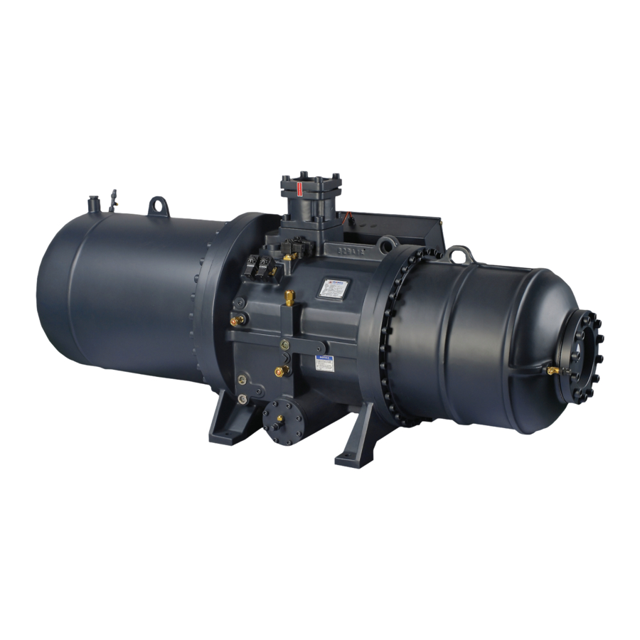
Hanbell RC2 Series Technical Manual
High voltage screw compressor
Hide thumbs
Also See for RC2 Series:
- Technical manual (84 pages) ,
- Installation & start?up manual (41 pages)
Table of Contents
Advertisement
Quick Links
Advertisement
Table of Contents

Related Manuals for Hanbell RC2 Series


Summary of Contents for Hanbell RC2 Series
-
Page 2: Table Of Contents
Contents 1. General ............................1 2. Specifications and concept of design ..................1 2.1 Compressor nomenclature....................1 2.2 High Voltage compressor specifications ................ 2 2.3 Compressor construction....................2 2.4 Design features ......................... 3 2.5 Compression process....................... 4 2.6 Capacity control system ....................4 2.6.1 4-step capacity control system ................ -
Page 4: General
HANBELL RC2 series semi-hermetic screw compressor is developed especially for applications in air-conditioning and refrigeration. With high operating load design, each HANBELL compressor is of high efficiency and reliability in all operating conditions such as thermal storage, heat pump system & refrigeration. Each HANBELL compressor has the latest and advanced 5-to-6 Patented Screw Rotor Profile designed to ensure high capacity and efficiency in all operating conditions. -
Page 5: High Voltage Compressor Specifications
1940 Nominal Horse Power: All the above Nominal Hp’s are not equal to the maximum compressor Hp. Please refer to Hanbell selection software’s output for rated current and Maximum Continuous Current-M.C.C according to various operating conditions while selecting sizes of contactor, cable, fuse and wire, etc…... -
Page 6: Design Features
Compressor technical features: Full product range- Hanbell provides a variety of high voltage motors, 3300V, 4160V, 6600V, 6000V and 10000V, for customer’s selection, which are compatible with R22, R134a, R404A, R507A and R407C. Other special working voltage and frequency are available after consulting Hanbell. -
Page 7: Compression Process
If solenoid valves and the piston do not work well in the capacity control system, this may result in capacity control failure. Before compressors stop, HANBELL strongly recommends that the unloading solenoid valve for step-less control system or the minimum-load solenoid valve for step control system should be kept opened for 30~60 seconds so the piston in the cylinder can approach the minimum-load position for lighter duty in next start. -
Page 8: Continuous (Step-Less) Capacity Control System
~ 100% It is very important for any controller to control loading and unloading in moderate condition. For smooth modulation, HANBELL installs an orifice in loading oil line to prevent too fast loading. Figure 4: Step-less capacity control... -
Page 9: Dual Capacity Control System (Optional)
2.6.3 Dual capacity control system (optional) Hanbell can provide dual capacity control system which is compatible for 4-step & step-less capacity control for customers’ ease of change as shown in Figure 5, and its control logic is the same as explained in either 2.6.1 or 2.6.2. - Page 10 2. When High Voltage series screw compressors operate under partial or full load within application limits, motor and discharge temperatures will rise concurrently. In order to keep compressors’ continuous running safe, Hanbell recommends using the following additional cooling devices : (1) Oil cooler (2) Liquid injection to chamber Please refer to Hanbell selection software for the application of additional cooling systems.
-
Page 11: Mcc & Lra
2.9 MCC & LRA Refrigerant : R134a 50Hz 60Hz Unit: Ampere Model 6000V 10000V 3300V 4160V 6600V RC2-1090A RC2-1280A RC2-1520A Refrigerant : R22, R407C, R404A 50Hz 60Hz Unit: Ampere Model 6000V 10000V 3300V 4160V 6600V RC2-1090B RC2-1280B RC2-1520B... -
Page 12: Lubricants
Bearings used in RC2 series compressors require a small and steady quantity of oil for lubrication. Oil injection into the compression chamber creates a film of oil for sealing in the compression housing to increase efficiency and also can dissipate part of compression heat. -
Page 13: Oil Change
Please follow the procedures mentioned above to change oil in the system. Check acidity of oil after 72 hours of operation and then change it again until acidity of oil becomes normal. 5. Please contact Hanbell local distributors/agents for choices of oil to be used. 3.3 Oil change Lubrication oil is an important element in chiller systems. -
Page 14: Compressor Lifting And Installation
4. Compressor lifting and installation 4.1 Compressor lifting Each HANBELL screw compressor has been carefully tested at the factory and every precautionary measures have been taken to make sure that compressors will keep in perfect condition when reach customers’ work. After the compressor arrives at your warehouse, please check if its crate is kept in good condition and check all the compressor accessories with shipping documents to see if there is any discrepancy. -
Page 15: Compressor Mountings
4.2 Compressor mountings The position of the compressor in refrigeration system should be accessible and make sure the chiller base or its site is far away from any heat source to prevent heat radiation. The compressor should also be installed as close as possible to the power supply for easier connection and it’s a must to keep good ventilation and low humidity condition in the site. -
Page 16: Installing The Compressor In A Sloping Position
Please contact HANBELL or local distributors for further layout recommendation. Figure 9: Limits of oblique angle for the installation of the... -
Page 17: Compressor Outline Drawings
4.5 Compressor outline drawings RC2-1090... - Page 18 RC2-1280...
- Page 19 RC2-1520...
-
Page 20: Compressors Accessories
4.6 Compressors accessories To supply “Total Solution” for customers, Hanbell designs complete standard and optional accessories according to various application requirements for safe and steady running as well as the best performance of compressors. 1. Compressor standard and optional accessories ●... - Page 21 For customers’ ease of stock control, possible modification of capacity-control logic in the future, or other special requirements of capacity control, Hanbell deliberately designs devices for stepless/step dual capacity control as optional accessory for customers’ choices. Logic of stepless/step dual capacity control is basically identical to that of stepless or step capacity control respectively.
- Page 22 Their dimensions refer to flange bushing dimensions and the table below. If bushing dimensions are not indicated in purchasing order, Hanbell will provide standard type. Suitable piping size for customers’ choice is also shown in the table below. If non-standard bushing is needed, please double-...
- Page 23 Steel 8" e. Suction and discharge stop valves For maintenance and service of compressor, it is recommended to install suction and discharge stop valves. Please refer to the following details of Hanbell stop valves. Stop Valve Size Model Discharge Suction RC2-1090 5″...
- Page 24 PTC temperature sensor In order to protect compressor, each High Voltage RC2 series compressor is installed with three PTC temperature sensors inside motor coil and another one at the discharge side of compressor. These sensors are connected with INT69HBY control module to monitor motor coil temperature and discharge temperature as well. If the temperature in one of the positions monitored exceeds the nominal response temperature of the respective PTC thermistor, resistance of sensor will increase and INT69HBY control module output relay will trip consequently.
- Page 25 Figure 16: RC2-1090, RC1280, RC1520 cable box i. External oil separator Hanbell specially designs a complete series of external oil separators – OS series with characteristics of high filtration efficiency and low pressure drop. The following table shows details of OS series: Note : It is recommended to install a buffer before the external oil separator to avoid noise and vibration which caused by resonance.
- Page 26 Figure 17: Vertical - OS40, OS50, OS65 Figure 18: Horizontal - OS80 Figure 19: Horizontal - OS100, OS125, OS150...
- Page 27 k. External oil filter It is suggested to install external oil filter in oil return line before suction port of compressor for safe running of compressor. Figure 20: External oil filter l. Oil flow switch Oil flow switch operates with external oil separator to prevent oil deficient compressor. Specification and installation of oil flow switch are shown as below: Specification: Setpoint range(H...
- Page 28 To effectively detect temperature of motor coil and adequately adjust volume of liquid injection by measured temperature, Hanbell specially mounts Pt100 or Pt1000 sensor on motor coil as a standard accessory for RC2-1090, 1280 & 1520. This temperature sensor along with controller of the system monitor motor coil temperature and then control on/off of liquid injection valve accordingly to provide suitable liquid injection as shown in the diagram below.
- Page 29 Recommended max. meas. Current for heat coefficient < 0.1K – DC0.2 ~ 2mA Sensor resistance at 0 ℃ - 1000Ω±1.20Ω Change of resistance 0 ~ 100 ℃ - 3.85Ω/K Insulation test voltage U is – AC 1.5kV Please specify Pt100 or Pt1000 sensor when placing orders to Hanbell. Figure 27: Pt1000 sensor...
-
Page 30: Installation And Connection Of The Compressor
4.7 Installation and connection of the compressor The diagrams below show installation and connection of compressors . RC2-1090, RC2-1280, RC2-1520... -
Page 32: Electrical Data And Design
5. Electrical data and design Warning During the installation, testing, service and troubleshooting of this compressor, it may be necessary to work with live electrical components. Please have a qualified licensed electrician or other individual who has been properly trained in handling live electrical components perform these tasks. -
Page 33: Compressor Protection Devices
Alarm lamp for this protector is required to be embedded on control panel as indicator. Any intention to short controllers for starting of compressors is prohibited. It is beyond Hanbell’s warranty of compressors if there is any action above mentioned found. -
Page 34: Protection Devices For High Voltage Compressor
Pt100 or Pt1000: HANBELL embeds 3 sets of Pt100 or Pt1000 sensors 1,2,&3 to monitor motor temperatures. You could choose one set of Pt100 or Pt1000 sensor aforementioned to be connected i.e. terminal 1 and 4, or terminal 2 and 4, or terminal 3 and 4. -
Page 35: Selection Of Magnetic Contactors
●Blow fuse on 3 phase bank of power factor improvement capacitors ●Unequal impedance in conductors of power supply wiring ●Unbalanced distribution of single phase loads such as lighting A 3-phase unbalanced voltages protector is upon request as optional accessory. Please contact Hanbell for more details. 5.4 Selection of magnetic contactors Please refer to AC3 specification, compressor’s selection program and design conditions of system to choose suitable... -
Page 36: Grounding
2. Standard voltage i s 2 20V. M aximum voltage i s 4. Power terminals and wire cables’ 230V. terminal connection. If there is other demand, contact HANBELL. 5. Grounded 3. Insulation resistance value should be above 6. Capacity of electrical accessories 2. - Page 37 The whole plant, especially the pipelines and capillary tubes must be checked for abnormal vibrations. Please contact HANBELL or local distributor if any abnormal vibrations or noise found while compressor is running. j. Regularly check the plant according to national regulations and the following items should also be checked: ●Operating data of the machine...
-
Page 38: Troubleshooting
Check and reset for proper superheat Condensing temperature too low Check means for regulating condensing temperature Note: The replacement of compressor parts should be performed only by a qualified / certified serviceman with full knowledge of HANBELL screw compressors or HANBELL service engineers. -
Page 39: Compressor Check List
6.3 Compressor check list Please fill out the blanks on the compressor checking list and send it to Hanbell when any compressor failure happens. Hanbell will reply and suggest a solution to the failure. CHECK LIST FOR TROUBLESHOOTING OF HANBELL SCREW COMPRESSOR Compressor model:... -
Page 40: Applications
Calculating the cooling capacity of liquid injection devices Liquid injection devices can be calculated with the HANBELL selection software or manually. For manual calculation, consider the most extreme conditions to be expected during actual operations i.e. minimum evaporating temperature, maximum suction gas super heat and condensing temperature. -
Page 41: Economizer Applications
With this form of operation, refrigeration capacity as well as system efficiency can be improved by means of a sub- cooling circuit or two-stage refrigerant expansion. Based on HANBELL’s extensive research, a special design of economizer connection has been developed so that the connection causes no additional back-flow losses during compression. As a result, compressor capacity is fully retained in all operating conditions. -
Page 42: Oil Pump Application
In addition to the installation of additional oil pump, high – low pressure differential switch is also recommended to be installed in this kind of system. Please contact Hanbell for more detailed information of oil pumps. Figure.35 Additional oil pump... -
Page 43: Important Notes Of Compressor Applications
The screw compressors are manufactured with finest quality material and are warranted for one year after completion of installation and commissioning at jobsite or up to18 months from the original date of sales by HANBELL or designated sales agent, whichever comes first.